US1856024A - Controlling and regulating device for compound internal combustion engines with exhaust turbines - Google Patents
Controlling and regulating device for compound internal combustion engines with exhaust turbines Download PDFInfo
- Publication number
- US1856024A US1856024A US698127A US69812724A US1856024A US 1856024 A US1856024 A US 1856024A US 698127 A US698127 A US 698127A US 69812724 A US69812724 A US 69812724A US 1856024 A US1856024 A US 1856024A
- Authority
- US
- United States
- Prior art keywords
- turbine
- engine
- governor
- internal combustion
- exhaust
- Prior art date
- Legal status (The legal status is an assumption and is not a legal conclusion. Google has not performed a legal analysis and makes no representation as to the accuracy of the status listed.)
- Expired - Lifetime
Links
- 238000002485 combustion reaction Methods 0.000 title description 34
- 230000001276 controlling effect Effects 0.000 title description 14
- 230000001105 regulatory effect Effects 0.000 title description 12
- 150000001875 compounds Chemical class 0.000 title description 4
- 239000007789 gas Substances 0.000 description 32
- 239000000446 fuel Substances 0.000 description 19
- 230000006835 compression Effects 0.000 description 8
- 238000007906 compression Methods 0.000 description 8
- 230000002000 scavenging effect Effects 0.000 description 7
- 230000033228 biological regulation Effects 0.000 description 4
- 230000007423 decrease Effects 0.000 description 4
- 230000003247 decreasing effect Effects 0.000 description 3
- 238000006073 displacement reaction Methods 0.000 description 3
- 230000000694 effects Effects 0.000 description 3
- 238000009434 installation Methods 0.000 description 3
- 238000010276 construction Methods 0.000 description 2
- 238000001816 cooling Methods 0.000 description 2
- 230000003584 silencer Effects 0.000 description 2
- VVNCNSJFMMFHPL-VKHMYHEASA-N D-penicillamine Chemical compound CC(C)(S)[C@@H](N)C(O)=O VVNCNSJFMMFHPL-VKHMYHEASA-N 0.000 description 1
- 239000000470 constituent Substances 0.000 description 1
- 229940075911 depen Drugs 0.000 description 1
- 230000001419 dependent effect Effects 0.000 description 1
- 239000000203 mixture Substances 0.000 description 1
- 239000011435 rock Substances 0.000 description 1
Images

Classifications
-
- F—MECHANICAL ENGINEERING; LIGHTING; HEATING; WEAPONS; BLASTING
- F02—COMBUSTION ENGINES; HOT-GAS OR COMBUSTION-PRODUCT ENGINE PLANTS
- F02D—CONTROLLING COMBUSTION ENGINES
- F02D13/00—Controlling the engine output power by varying inlet or exhaust valve operating characteristics, e.g. timing
- F02D13/02—Controlling the engine output power by varying inlet or exhaust valve operating characteristics, e.g. timing during engine operation
- F02D13/0203—Variable control of intake and exhaust valves
- F02D13/0215—Variable control of intake and exhaust valves changing the valve timing only
-
- F—MECHANICAL ENGINEERING; LIGHTING; HEATING; WEAPONS; BLASTING
- F02—COMBUSTION ENGINES; HOT-GAS OR COMBUSTION-PRODUCT ENGINE PLANTS
- F02B—INTERNAL-COMBUSTION PISTON ENGINES; COMBUSTION ENGINES IN GENERAL
- F02B37/00—Engines characterised by provision of pumps driven at least for part of the time by exhaust
- F02B37/12—Control of the pumps
- F02B37/22—Control of the pumps by varying cross-section of exhaust passages or air passages, e.g. by throttling turbine inlets or outlets or by varying effective number of guide conduits
-
- F—MECHANICAL ENGINEERING; LIGHTING; HEATING; WEAPONS; BLASTING
- F02—COMBUSTION ENGINES; HOT-GAS OR COMBUSTION-PRODUCT ENGINE PLANTS
- F02D—CONTROLLING COMBUSTION ENGINES
- F02D13/00—Controlling the engine output power by varying inlet or exhaust valve operating characteristics, e.g. timing
- F02D13/02—Controlling the engine output power by varying inlet or exhaust valve operating characteristics, e.g. timing during engine operation
- F02D13/0261—Controlling the valve overlap
-
- F—MECHANICAL ENGINEERING; LIGHTING; HEATING; WEAPONS; BLASTING
- F02—COMBUSTION ENGINES; HOT-GAS OR COMBUSTION-PRODUCT ENGINE PLANTS
- F02D—CONTROLLING COMBUSTION ENGINES
- F02D23/00—Controlling engines characterised by their being supercharged
-
- F—MECHANICAL ENGINEERING; LIGHTING; HEATING; WEAPONS; BLASTING
- F02—COMBUSTION ENGINES; HOT-GAS OR COMBUSTION-PRODUCT ENGINE PLANTS
- F02B—INTERNAL-COMBUSTION PISTON ENGINES; COMBUSTION ENGINES IN GENERAL
- F02B3/00—Engines characterised by air compression and subsequent fuel addition
- F02B3/06—Engines characterised by air compression and subsequent fuel addition with compression ignition
-
- Y—GENERAL TAGGING OF NEW TECHNOLOGICAL DEVELOPMENTS; GENERAL TAGGING OF CROSS-SECTIONAL TECHNOLOGIES SPANNING OVER SEVERAL SECTIONS OF THE IPC; TECHNICAL SUBJECTS COVERED BY FORMER USPC CROSS-REFERENCE ART COLLECTIONS [XRACs] AND DIGESTS
- Y02—TECHNOLOGIES OR APPLICATIONS FOR MITIGATION OR ADAPTATION AGAINST CLIMATE CHANGE
- Y02T—CLIMATE CHANGE MITIGATION TECHNOLOGIES RELATED TO TRANSPORTATION
- Y02T10/00—Road transport of goods or passengers
- Y02T10/10—Internal combustion engine [ICE] based vehicles
- Y02T10/12—Improving ICE efficiencies
Definitions
- the present invention relates to internal combustionengines to which thecharge is supplied under pressure by a compressor driven by a turbine that is actuated bythe 5 exhaust gases of the internal combustion engine.
- the internal combustion engine may be regulated by a gov- 1 ernor in any well-known way, whereas the exhaust gas turbine runs independently of mechanical driving connection with the engine, its driving power being derived entirely from the engine exhaust ases delivered to it. It is obvious that there is only a small range of load where the internal combustion engine, exhaust gas turbine, and
- An object of this invention is to provide governing devices and connections by which the internal combustion engine, the exhaust gas turbine, and turbo blower are-linked together and influence each other, all three of them, or at l'e'ast the turbine and engine, or the blower and engine, so that each one gives the best performance under all load conditions.
- Another object of this invention is to so regulate the quantity of compressed air sup- 'plied the engine and the scavenging period of the engine that proper temperature conditions in the engine and exhaust gases will be maintained under all conditions of load.
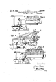
- FIG. 1 shows, in a diagrammatic'manner, an internal combustion engine, an exhaust turbine, a compressor,-and connections between these parts, and interconnected and jointly influenced regulating mechanism for these parts;
- Fig. 2 shows a modified form of regulating mechanism
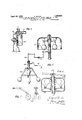
- FIG. 3 shows a further embodiment of the invention
- Fig. 4 shows diagrammatically the construction of the exhaust turbine
- Fig. 5 is an enlarged' view, partially in section. showing the type of governor for use in the mechanism according to Fig. 1, and the governor and regulating connections adapted for use in the mechanism according to Fig. 3; V
- Fig. 6 is an enlarged view; partially in section, of the governor and connections adapted for use in the mechanism shown in Fig. 2;
- Fig. 7 shows the cam for the engine inlet and exhaust valves, the left-hand view being as from the right in Fig. 2, and the righthand view being as from the rear in Fig. 2;
- Fig. 8 is an enlarged sectional view of a part of Fig. 3 showing the connection between the compressor and governor;
- Fig. 9 is a sid view, partially in section, of a part of Fig. 8;
- Fig. 10 is a top view of Fig. 8, partially in section.
- Fig. 11 is a side view, partially in section, of the governor and connections for controlling the fuel pump shown in Fig. 3.
- a comipressor 6 is provided in which the air for the internal combustion engine is compressed and is then" supplied to the engine through conduit 3.
- the turbine is actuated by the exhaust gases of the internal combustion engine supplied to the turbine through the conduit 4.
- the mechanism for supplying the fuel of the charge to the engine is not shown in high speed naturally Fig. 1, but this'may be similar to the fuel pump and controllin mechanism diagrammatically shown in Fig. 3 and shown more in detail in Fig. 11.
- the special manner of controlling and regulating the various arts of the power installation is based on t e fact that the delivery pressure of the compressor depends on the speed of the turbine 7 which in turn is influenced by the quantity of exhaust as delivered thereto from the engine and the admission area of the turbine, which can be varied by means of a slide 9, the position of which r'na be varied to open or close more or less tur ine inlet nozzles 9.
- the position of the slide 9 is controlled by a governor 5 dependent on the speed of the internal combustion engine and by another factor, such as, for instance, the pressure of the air supplied by the compressor.
- the engine when operating at elivers a larger amoun of exhaust gases to the turbine.
- the arrangement of the mechanism accord ing to this invention is such that the governor of the internal combustion engine by means connecting linkage and levers such as link 22", a bell crank, link 22', and lever 22 influ ences the position of slide 9 which influences the speed of the exhaust turbine and consequently controls the output and delivery pressure of the compressor.
- the osition of the slide 9, according to the embodiment of Fig. 1, is also afiected by mechanism responslve to the pressure of the air supplied by compressor 6.
- the pressure responsive device comprises a piston 21 moving in a cylinder 13 and having one side subjected to the pressure of the air supplied by the compressor.
- a coil spring 23 Is attached at one end to the piston 21 and to a fixed end of the cylinder at its other end.
- the piston 21 is connected with slide 9 by means of a rod 14 which passes through one end of the cylinder.
- One end of lever 22 is attached to this rod so that both the engine governor 5 andthe pressure responsive piston 21 influence the position of slide 9.
- the lever 22 is provided with an extension by means of which'the position of slide 9 and piston 21 may be manually controlled.
- the governor device 5 is of a conventional type, and it is obvious that upon increase of the speed of the en e the governor will exert a push upon Ii 22' and consequently tend to move slide 9 to the right to a position covering more of the .turbine inlet nozzles 9', while, on the other hand, a decreased engine speed tends to move slide 9 to the left and uncover more nozzles.
- Valves 11 and 12 may be in conduits 3 and 4 respectively for the purpose of duits with the atmosphere when it is not de sired to precompress the charge.
- Fig. 2 shows an embodiment of the invention in .which the inlet and exhaust valves of the engine are so controlled by means of cams 27 and 28 that scavenging of the cylinders is effected.
- cams 27 and 28 The construction of these cams is shown more in detail in Fig. 7.
- a novel feature of the .controllmg and regulatin means consists in controlling the timing 0' the inlet valves-25 and the outlet valves 26.
- the timing of the valves may be such that the inlet and outlet valves of a cylinder remain open simultaneously.
- the parts of the valves that touch the rollers of the valve rockers are tapered so that by an axial displacement of the cams, the timing of the valves may be so adjusted as to be open over-a longer period.
- the position of a cam for maximum lift and longest open period is chain-dotted, for medium lift is full lines, and for minimum lift and minimum open'period is dotted lines.
- the means for effecting this adjustment are diagrammatically indicated and, as the cams are mounted on the cam shaft 29, the adjustment ma be obtained 'by an axial displacement of t e shaft 29, for instance, by means ofrocking bell crank lever 33.
- the fresh charge enters through the conduit 3 in which the cylinder forces the burnt Kgases present in the cylinders through the e aust pipe 4 to the turbine 7.
- the engine valves may be permitting direct connection of these conkept open sufiiciently long and the air pres- 130 exhaust is obtained. scavenge effectively in all cases, the device sure sufiiciently high that 'after completion of the scavenging action the inlet and exhaust valves may remain open and fresh compressed air from compressor 6 passes through the cylinder into the conduit 4 leading to the turbine 7.
- the controlling action of the valves by the engine governor may be modified to some extent by the temperature of the exhaust gases which is effective on expansible thermostat 33 suspended between bell crank levers 33 and 33" and located in the exhaust manifold 4.
- thermostat 33 tends to rock bell crank 33 to the right and effects axial displacement of shaft 29 and cams 27 and 28 to the right whereby the valves are held open-for longer periods and more complete scavenging and cooling of the In order to be able to may be so built that it causes the pressure in conduit 3 to be higher than the pressure in conduit 4 at all loads.
- an extension of the thermostat is connected to an arm of bell crank lever 33 which in turn is connected with link 8- which controls slides 9 and 31.
- the charging pressure that is, the pressure in conduit 3 is controlled by the slide 31 operated by rod 8 under the influence of engine governor 5a.
- the controlling influence of engine governor 5a on these slide valves may be adjusted by turnbuckles 10 and 32.
- turnbuckles maybe adjusted as follows: At full load the engine should run at a definite speed under the control of the engine governor. By turning alternatively turnbuckles 10 and 32 the positions of slides 9 and 31 are found insuch a way that the revolutions of the turbine are as predetermined, for instance, 3000 R. P. 11., and the required pressure in pipe 3 is obtained.- It is also apparent that adjustment of turnbuckle 10 adjusts the axial position of cam shaft 29 which is under the'control of engine governor 5a through connections comprising link 8, belt crank 33". thermostat 33, and bell crank 33', the controlling action beto stop ,the engines.
- thermostat 33 modified to some extent by thermostat 33.
- thermostat 33 is effective to some extent to modify the controlling action of governor 5a on the positions of slides 9 and 31 and of the fuel throttle lever 52. Expansion of the thermostat 33 exerts a force on link 8 to the right which by reference to Fig. 6 it will be seen causes the governor sleeve to rise and by reference to Fig. 11, it will be seen that this movement results in feeding more fuel to the engine. As the load on the engine is still the same, the internal combustion engine speeds. up. The sameload at a higher speed of the engine causes a lower mean effective pressure:
- thermostat 33 acts now in the opposite direction, so that the temperatures increase again somewhat.
- Thisregulatioh by thermostat 33 resembles the regulation of an engine by an ordinary governor in which, when loadis thrown on the engine the R. P. M. decrease, then increase again to stabilize somewhat between the maximum and minimum R. P. M., for which the governor is designed. Similarly these temperatures stabilize between the maximum temperature and the minimum temperature the thermostat is designed for.
- FIG. 3 A further arrangement of the control and regulation of ,a power installation according to the invention is illustrated in Fig. 3.
- Internal combustion engines are provided with a control gear, which enables to start the engine, to run the engine at different loads, or Gears of this kind are well known to those skilled in the art and do not need to be descr bed here. Provision is made in this case that ,”simultaneously with the setting of the control mechanism 34 of the internal combustion engine to the stop or small load position for the engine the brought into open communication with .the atmosphere.
- valves are provided for easier starting, so that instead of drawing in air through the blower, the air 1s drawn 7 in directly from the atmosphere, and instead of exhausting through the turbine the exhaust gases pass through valve 12 and silencer 39 directly to the atmosphere.
- the resistance of the intake and of the exhaust are thus appropriatelg'hreduced, and uicker startin is possible.
- e position of t e control mec anism 34 shown in full lines corresponds to the working of the e, that shown in dotted lines to the starting with compressed air, and the intermediate position to the stopp' oftheengine.
- j e regulation of the com ressor aggregate may also be made depen cut on the internal combustionengine, as is indicated in .Fig. 3 by thelinks 8.
- governor sleeve 47 moves downwardly
- sp 43 is tensioned
- the force exerted on governor' 5 b governor '37 is, thereby increased and e sleeve of vernor 5 tends to move u wardly and the alls to move inwardly. ovement of the sleeve of governor 5 upwardly decreases the tension in spring. 43. 'At the same time, movement ofslide valve 9 'to'the right increases the inlet area of the turbine, "and its speed is consequently reduced.
- This turbine (Fi 4) has the 'push rod/ v46 for moving the sli e 9 and one of its chamhers is indicated by 7*. It. will be readily understood that by cutting ofi' one or more of chambers 7 the inlet area becomes smaller, the pressure ahead of the turbine increases and the speed of the turbine also increases.
- Figs. 8, 9 and 10 illustrate how governors With 13 and 37 may be driven.
- Numerals 56 58 are sprockets linked together by a chain 57 and keyed on shafts 61 and 62 respective? ly.
- a pinion ear 59 on shaft 62 is in mesh with pinion eyed on governor shaft 63.
- the details of the governing mechanism, Fig. 5, include the governor 5 of the internal combustion engine and the governor 37 of the aggregate linked together so as to mutually control each other.
- the governor. 5 of the engine regulates the speed of the engine in the orthodox way, whereby the speed rises a few full load to no load as is well known in the art. If the engine is running at half load, for instance, inuch less fuel is fed to. the engine, the temperature of the exhaust gases decreases therefore, hence theirvolume becomes smaller and the revolutions of the turbine 7 drop considerably. If the turbine 7 drives a generator 24, the tension of the latter falls in the same tions of the turbine As the blower is also directly connected to the turbine, its capacity percent from I roportion as the revoluis also reduced and the delivery pressure 99 lower.
- the compression pressure depends on the initial pressure in the cylinder at the beginning of the compression stroke; the compression pressure becomes lower, the lower this initial pressure is.
- the pressure at the beginning of the compression stroke can drop to such an extent that the compression pressure becomes so low, that the ignition temperature is not reached any more, and the engine would come to stop.
- the regulation according to the invention allows for closing nozzles at the turbine inlet thus raising the pressure ahead of the turbine and therefore also raising the turbine speed. The charging pressure is thereby increased and good perormance of the engine insured also at very low loads.
- the devices 34, 35 and 11; 36 and 12 effect the changing over from starting (dotted line position Fig. 3) to working position, (full line position), so that when lever 34 is moved gradually, at first only little exhaust gases pass through the turbine, not enough to turn it, but sufficient to heat it up. llIoving lever 34 more and more to full line position, the turbine starts to rotate slowly and speed up, reaching full speed when lever 34 reaches its final position when 11 and 12 close against the atmosphere or the exhaust silencer 39, respectively.
- the quantity, the pressure or the proportion of mixture respectively of the charge, the fuel admission, the pressure in front of the turbine or the speeds of the constituent parts of the power installation are regulated.
- a power plant comprising an internal combustion engine, a governor therefor, a fuel pump, means to control said fuel pump 'by said governor, an exhaust gas turbine, a
- compressor driving connection between said turbine and compressor, means to deliver the charge from said compressor to said internal combustion engine, means to convey the exhaust gases of said internal combustion engine to said turbine, adjustable inlet openings to said turbine, means tocontrol said inlet openings, means to modify the action of sald controlling means of said inlet openings by the engine governor.
- a power plant comprising an internal combustion engine, a governor therefor, a fuel pump, means to control said fuel pump 7 by said governor, an exhaust gas turbine, a compressor, driving connection between said turbine and compressor, means to deliver the charge from said compressor to said internal combustion engine, means to convey the exhaust gases of said internal combustion engine to said turbine, adjustable inlet openings to said turbine, a governor for said exhaust gas turbine, a slide to control said inlet openingsto said turbine, means to connect theturbine governor to said slide, connecting means between the engine governor and the turbine governor, a yielding member in said connecting means.
- a power plant comprising an internal combustion engine, a governor therefor, a fuel pump, means to control said fuel pump by said governor, an exhaust gas turbine, a compressor, a driving connection between the turbine and compressor, means to deliver the charge from said compressor to said internal combustion engine, means to convey the exhaust gases of said internal combustion engine to said turbine, adjustable inlet openings to said turbine, a governor for said ex- 95.
- haust gas turbine a slide to control said inlet openings to said turbine, means to connect the turbine, governor to said slide, connecting means between the engine governor and the turbine governor, and an adjustable member in said connecting means.
- a power plant comprising an internal combustion engine, a governor therefor, a fuel pump, means to control said fuel pump by said governor, an exhaust gas turbine, a compressor, a driving connection between said turbine and compressor, means to deliver the charge from said compressor to said internal combustion engine, means to convey the ex- ALFRED BUCHI.
Landscapes
- Engineering & Computer Science (AREA)
- Chemical & Material Sciences (AREA)
- Combustion & Propulsion (AREA)
- Mechanical Engineering (AREA)
- General Engineering & Computer Science (AREA)
- Supercharger (AREA)
- Output Control And Ontrol Of Special Type Engine (AREA)
Description
April 26, 1932. A. BUCHI 1,856,024
CONTROLLING AND REGULATING DEVICE FOR COMPOUND INTERNAL COMBUSTION ENGINES WITH EXHAUST TURBINES Filed March 10, 1924 3 Sheets-Sheet 1 I :3 Z 2 o 4 I 5 m i 9 a J ff 4 1 i u u ffrwenior;
April 26, 1932.
4 2 2 0 t 6 L 8 5 m 8 N S ,R IE 5 T t N e I 9 n a 5 0 N A. BUCHI CONTROLLING AND REGULATING DEVICE FOR COMP COMBUSTION ENGINES WITH EXHAUST TURBI Filed March 10, 1924 lllllllll Aprll 26, 1932. BUCH] 1,856,024
CONTROLLING AND REGULATING DEVICE FOR COMPOUND INTERNAL COMBUSTION ENGINES WITH EXHAUST TURBINES Filed March 10, 1924 5 Sheets-Sheet 3 IIJIJIIII Patented A r. 26, 1932 UNITE STATES PATENT orl-"lcr.-
ALFRED BUCHI, OF WINTER'IHUR, SWITZERLAND CONTROLLING AND REGULATING DEVICE FOR COMPOUND INTERNAL COMBUSTION ENGINES WITH EXHAUST TUBIBINES Application filed March 10, 1924, Serial No. 698,127, and in Switzerland March 21, 1923.
The present invention relates to internal combustionengines to which thecharge is supplied under pressure by a compressor driven by a turbine that is actuated bythe 5 exhaust gases of the internal combustion engine. It is known that the internal combustion engine may be regulated by a gov- 1 ernor in any well-known way, whereas the exhaust gas turbine runs independently of mechanical driving connection with the engine, its driving power being derived entirely from the engine exhaust ases delivered to it. It is obvious that there is only a small range of load where the internal combustion engine, exhaust gas turbine, and
blower'work with the maximum efliciency. An object of this invention is to provide governing devices and connections by which the internal combustion engine, the exhaust gas turbine, and turbo blower are-linked together and influence each other, all three of them, or at l'e'ast the turbine and engine, or the blower and engine, so that each one gives the best performance under all load conditions.
Another object of this invention is to so regulate the quantity of compressed air sup- 'plied the engine and the scavenging period of the engine that proper temperature conditions in the engine and exhaust gases will be maintained under all conditions of load.
constructional examples of the subject matter of the present invention are illustrated on the accompanying drawings, in which Fig. 1 shows, in a diagrammatic'manner, an internal combustion engine, an exhaust turbine, a compressor,-and connections between these parts, and interconnected and jointly influenced regulating mechanism for these parts;
Fig. 2 shows a modified form of regulating mechanism;
. Fig. 3 shows a further embodiment of the invention; I
Fig. 4 shows diagrammatically the construction of the exhaust turbine;
Fig. 5 is an enlarged' view, partially in section. showing the type of governor for use in the mechanism according to Fig. 1, and the governor and regulating connections adapted for use in the mechanism according to Fig. 3; V
Fig. 6 is an enlarged view; partially in section, of the governor and connections adapted for use in the mechanism shown in Fig. 2;
Fig. 7 shows the cam for the engine inlet and exhaust valves, the left-hand view being as from the right in Fig. 2, and the righthand view being as from the rear in Fig. 2;
Fig. 8 is an enlarged sectional view of a part of Fig. 3 showing the connection between the compressor and governor;
Fig. 9 is a sid view, partially in section, of a part of Fig. 8;
Fig. 10 is a top view of Fig. 8, partially in section; and
Fig. 11 is a side view, partially in section, of the governor and connections for controlling the fuel pump shown in Fig. 3.
In the drawings, the various machinery parts and regulating devices are-only diagrammatically'indicated in such a manner as is considered suflicient for illustrating the present invention, and constructional details of the parts shown will suggest themselves to persons skilled in the art.
Referring to Fig. 1 of the drawings, 1 denotes an internal combustion engine having four working cylinders 2, to which a pre compressed charge is supplied by means of the conduit 3. The exhaust gases leave the cylinders through the conduit 4. The internal combustion engine is influenced by a governor 5 which regulates the speed of the engine by controlling the quantity of fuel supplied thereto by a mechanism such as that shown generally at 38 in Fig. 3. In accordance with thespecial arrangement of power engine to which the invention relates, a comipressor 6 is provided in which the air for the internal combustion engine is compressed and is then" supplied to the engine through conduit 3. The compressor 6, which in thepresent example, is shown as a compresor of the centrifugaltype, is directly driven by the turbine 7 The turbine is actuated by the exhaust gases of the internal combustion engine supplied to the turbine through the conduit 4. The mechanism for supplying the fuel of the charge to the engine is not shown in high speed naturally Fig. 1, but this'may be similar to the fuel pump and controllin mechanism diagrammatically shown in Fig. 3 and shown more in detail in Fig. 11.
The special manner of controlling and regulating the various arts of the power installation is based on t e fact that the delivery pressure of the compressor depends on the speed of the turbine 7 which in turn is influenced by the quantity of exhaust as delivered thereto from the engine and the admission area of the turbine, which can be varied by means of a slide 9, the position of which r'na be varied to open or close more or less tur ine inlet nozzles 9. The position of the slide 9 is controlled by a governor 5 dependent on the speed of the internal combustion engine and by another factor, such as, for instance, the pressure of the air supplied by the compressor. The engine when operating at elivers a larger amoun of exhaust gases to the turbine.
The arrangement of the mechanism accord ing to this invention is such that the governor of the internal combustion engine by means connecting linkage and levers such as link 22", a bell crank, link 22', and lever 22 influ ences the position of slide 9 which influences the speed of the exhaust turbine and consequently controls the output and delivery pressure of the compressor.
The osition of the slide 9, according to the embodiment of Fig. 1, is also afiected by mechanism responslve to the pressure of the air supplied by compressor 6. The pressure responsive device comprisesa piston 21 moving in a cylinder 13 and having one side subjected to the pressure of the air supplied by the compressor. A coil spring 23 Is attached at one end to the piston 21 and to a fixed end of the cylinder at its other end. The piston 21 is connected with slide 9 by means of a rod 14 which passes through one end of the cylinder. One end of lever 22 is attached to this rod so that both the engine governor 5 andthe pressure responsive piston 21 influence the position of slide 9. The lever 22 is provided with an extension by means of which'the position of slide 9 and piston 21 may be manually controlled. A vernor mechanism suitable for. influencing t e speed of the engine and the position of slide 9 is shown in some detail in Fig. 5. The governor device 5 is of a conventional type, and it is obvious that upon increase of the speed of the en e the governor will exert a push upon Ii 22' and consequently tend to move slide 9 to the right to a position covering more of the .turbine inlet nozzles 9', while, on the other hand, a decreased engine speed tends to move slide 9 to the left and uncover more nozzles.
It is apparent that in normal operation, that is, when the engine is operating under load and arecompressed charge is utilized, a number 0 forces will mutually contribute to control the operation of the engine and auxiliary mechamsm. Upon an increase of speed the engine governor 5 tends to move slide 9 to the right thereby tending to decrease the number of turbine nozzles throu h which the exhaust gas may pass, whereby t e pressure of the gas in exhaust conduit 4 is increased and the speed of the gas passing through the turbine isincreased. With increased pressure and speed of. the exhaustin which the forces effective on it are in equilibrium and the normal operation of the engine will thereby be automatically maintained.
Fig. 2 shows an embodiment of the invention in .which the inlet and exhaust valves of the engine are so controlled by means of cams 27 and 28 that scavenging of the cylinders is effected. The construction of these cams is shown more in detail in Fig. 7.
A novel feature of the .controllmg and regulatin means consists in controlling the timing 0' the inlet valves-25 and the outlet valves 26. The timing of the valves may be such that the inlet and outlet valves of a cylinder remain open simultaneously.
As illustrated in Fig. 7, the parts of the valves that touch the rollers of the valve rockers are tapered so that by an axial displacement of the cams, the timing of the valves may be so adjusted as to be open over-a longer period. In Fig. 7 the position of a cam for maximum lift and longest open period is chain-dotted, for medium lift is full lines, and for minimum lift and minimum open'period is dotted lines.
The means for effecting this adjustment are diagrammatically indicated and, as the cams are mounted on the cam shaft 29, the adjustment ma be obtained 'by an axial displacement of t e shaft 29, for instance, by means ofrocking bell crank lever 33.
During the scavenging action the fresh charge enters through the conduit 3 in which the cylinder forces the burnt Kgases present in the cylinders through the e aust pipe 4 to the turbine 7. The engine valves may be permitting direct connection of these conkept open sufiiciently long and the air pres- 130 exhaust is obtained. scavenge effectively in all cases, the device sure sufiiciently high that 'after completion of the scavenging action the inlet and exhaust valves may remain open and fresh compressed air from compressor 6 passes through the cylinder into the conduit 4 leading to the turbine 7. By this provision, the temperature of the exhaust gases passing to and through link 8 and slide valves 9 and 31, the
ing modified to some extent by thermostat 33.
Assuming constant load on'the engine, theposition of the governor lever remains unaltered and bell crank lever 33 isstationary. If for any reasons the exhaust temperatures become higher, the thermostat 33, subject to the temperature of the exhaust gases, expands-and. as movement of lever 33" is resisted by the influence of the engine governor, bell crank lever 33 is rocked in a clockwise direction. By this movement, cam shaft 29 is moved to the right and the engine valves are held open for longer periods whereby complete scavenging is effected and additional cooling air passes through the cylinders into the exhaust.- This effects a reduction of the exhaust temperature. If, on the other hand, the temperature of the exhaust gases becomes abnormally low, thermostat 33 contracts and pulls cam shaft 29 to the left, whereby the open periods of the engine valves are shortened and the temperatureof the exv .haust gases rises.
It is also apparent that the thermostat 33 is effective to some extent to modify the controlling action of governor 5a on the positions of slides 9 and 31 and of the fuel throttle lever 52. Expansion of the thermostat 33 exerts a force on link 8 to the right which by reference to Fig. 6 it will be seen causes the governor sleeve to rise and by reference to Fig. 11, it will be seen that this movement results in feeding more fuel to the engine. As the load on the engine is still the same, the internal combustion engine speeds. up. The sameload at a higher speed of the engine causes a lower mean effective pressure:
Lower mean effective pressures result in lower temperatures. The temperature being lower the thermostat 33 acts now in the opposite direction, so that the temperatures increase again somewhat. Thisregulatioh by thermostat 33 resembles the regulation of an engine by an ordinary governor in which, when loadis thrown on the engine the R. P. M. decrease, then increase again to stabilize somewhat between the maximum and minimum R. P. M., for which the governor is designed. Similarly these temperatures stabilize between the maximum temperature and the minimum temperature the thermostat is designed for. I
A further arrangement of the control and regulation of ,a power installation according to the invention is illustrated in Fig. 3. Internal combustion engines are provided with a control gear, which enables to start the engine, to run the engine at different loads, or Gears of this kind are well known to those skilled in the art and do not need to be descr bed here. Provision is made in this case that ,"simultaneously with the setting of the control mechanism 34 of the internal combustion engine to the stop or small load position for the engine the brought into open communication with .the atmosphere. 7 The said valves are provided for easier starting, so that instead of drawing in air through the blower, the air 1s drawn 7 in directly from the atmosphere, and instead of exhausting through the turbine the exhaust gases pass through valve 12 and silencer 39 directly to the atmosphere.- The resistance of the intake and of the exhaust are thus appropriatelg'hreduced, and uicker startin is possible. e position of t e control mec anism 34 shown in full lines corresponds to the working of the e, that shown in dotted lines to the starting with compressed air, and the intermediate position to the stopp' oftheengine. j e regulation of the com ressor aggregate may also be made depen cut on the internal combustionengine, as is indicated in .Fig. 3 by thelinks 8. Accordin to the speed the right when the governor of the e the governors eeve is ma higher or ower position, thereby influencing also the position of link 8, which is more to Th sleeve its. upper'position. e'spring 43is t ere ore more or less stressed to exert difierent forces on the governor 37 .of the compressor gate and accordingly changes the tion of slide 9 by means of link 46. If for any reason the speed of turbine 7 increases, the
' balls of governor 37 (Fig. 5) move outwardly, governor sleeve 47 moves downwardly, sp 43 is tensioned, and slide valve. 9 1s mov' to the right. The force exerted on governor' 5 b governor '37 is, thereby increased and e sleeve of vernor 5 tends to move u wardly and the alls to move inwardly. ovement of the sleeve of governor 5 upwardly decreases the tension in spring. 43. 'At the same time, movement ofslide valve 9 'to'the right increases the inlet area of the turbine, "and its speed is consequently reduced. This reduction of speed permits the balls of governor 37 to move inwardly and sleeve" 47 upwardl whereby slide valve 9 is pulled to the 1e and occupies a 'tion somewhere between its positlon and its extreme position at the right during the operation justdescribed. I
It is obvious that when the area 'of the turbine nozzles is decreased and the volume of gas passing is the same, the speed of the gas is increased and consequently the turbine speed also increases.
This turbine (Fi 4) has the 'push rod/ v46 for moving the sli e 9 and one of its chamhers is indicated by 7*. it. will be readily understood that by cutting ofi' one or more of chambers 7 the inlet area becomes smaller, the pressure ahead of the turbine increases and the speed of the turbine also increases.
. Figs. 8, 9 and 10 illustrate how governors With 13 and 37 may be driven. Numerals 56 58 are sprockets linked together by a chain 57 and keyed on shafts 61 and 62 respective? ly. A pinion ear 59 on shaft 62 is in mesh with pinion eyed on governor shaft 63.
The details of the governing mechanism, Fig. 5, include the governor 5 of the internal combustion engine and the governor 37 of the aggregate linked together so as to mutually control each other.
The governor. 5 of the engine regulates the speed of the engine in the orthodox way, whereby the speed rises a few full load to no load as is well known in the art. If the engine is running at half load, for instance, inuch less fuel is fed to. the engine, the temperature of the exhaust gases decreases therefore, hence theirvolume becomes smaller and the revolutions of the turbine 7 drop considerably. If the turbine 7 drives a generator 24, the tension of the latter falls in the same tions of the turbine As the blower is also directly connected to the turbine, its capacity percent from I roportion as the revoluis also reduced and the delivery pressure 99 lower.
When the load is thrown off the internal combustion engine, the sleeve of governor 5 moves downward and link 8 and slide 9 are i creases and the quantity and pressure of the charge accordingly rises.
On the other hand,-if high overloads are dealt with and'a big fuel quantity is fed to the en 'ne, the sleeve of governor 5 -moves upwa link 84s pushed to the right, spring 43 is compressed, and being in tension, the force extended thereon decreased, so that the sleeve of governor 37 moves downward, pushmg open more turbine nozzles so that the pressure ahead ofv the nozzles drop. Due to the increased quantity of fuel, the tem erature of the exhaust gases rises and there ore also the pressure ahead of the turbine. This would considerably increase the revolutions of thethis is avoided and the'pressure ahead of the turbine as well as the delivery pressure-- reduced as hereinbefore described. In this way too high initial pressures in the engine are avoided and hence also too high maximum pressures and temperatures. Longer life of piston, cylinder head valves is thus insured. low loads, only a small amount of link 46 to the right to cause slide 9 to fuel is fed to the internal combustion engine. Without applying the present invention, the exhaust temperatures would become low, the exhaust turbine would run slowly,'and hence the blower also, so that the delivery pressure of the latter would be low. In internal combustion engines without spark plugs, ignition occurs only when the temperature atthe end of the compression is at least as high as the ignition temperature. This temperature at the end ofthe compressionstroke depends on the compression pressure and is the lower, the lower the compression pressure is. As the compression pressure depends on the initial pressure in the cylinder at the beginning of the compression stroke; the compression pressure becomes lower, the lower this initial pressure is. At low loads the pressure at the beginning of the compression stroke can drop to such an extent that the compression pressure becomes so low, that the ignition temperature is not reached any more, and the engine would come to stop. To avoid this, the regulation according to the invention allows for closing nozzles at the turbine inlet thus raising the pressure ahead of the turbine and therefore also raising the turbine speed. The charging pressure is thereby increased and good perormance of the engine insured also at very low loads.
The devices 34, 35 and 11; 36 and 12 effect the changing over from starting (dotted line position Fig. 3) to working position, (full line position), so that when lever 34 is moved gradually, at first only little exhaust gases pass through the turbine, not enough to turn it, but sufficient to heat it up. llIoving lever 34 more and more to full line position, the turbine starts to rotate slowly and speed up, reaching full speed when lever 34 reaches its final position when 11 and 12 close against the atmosphere or the exhaust silencer 39, respectively.
With the arrangement according to the invention hereinbefore described, the quantity, the pressure or the proportion of mixture respectively of the charge, the fuel admission, the pressure in front of the turbine or the speeds of the constituent parts of the power installation are regulated.
I claim:
1. In a power plant comprising an internal combustion engine, a governor therefor, a fuel pump, means to control said fuel pump 'by said governor, an exhaust gas turbine, a
compressor, driving connection between said turbine and compressor, means to deliver the charge from said compressor to said internal combustion engine, means to convey the exhaust gases of said internal combustion engine to said turbine, adjustable inlet openings to said turbine, means tocontrol said inlet openings, means to modify the action of sald controlling means of said inlet openings by the engine governor.
2. In a power plant comprising an internal combustion engine, a governor therefor, a fuel pump, means to control said fuel pump 7 by said governor, an exhaust gas turbine, a compressor, driving connection between said turbine and compressor, means to deliver the charge from said compressor to said internal combustion engine, means to convey the exhaust gases of said internal combustion engine to said turbine, adjustable inlet openings to said turbine, a governor for said exhaust gas turbine, a slide to control said inlet openingsto said turbine, means to connect theturbine governor to said slide, connecting means between the engine governor and the turbine governor, a yielding member in said connecting means.
3. In a power plant comprising an internal combustion engine, a governor therefor, a fuel pump, means to control said fuel pump by said governor, an exhaust gas turbine, a compressor, a driving connection between the turbine and compressor, means to deliver the charge from said compressor to said internal combustion engine, means to convey the exhaust gases of said internal combustion engine to said turbine, adjustable inlet openings to said turbine, a governor for said ex- 95. haust gas turbine, a slide to control said inlet openings to said turbine, means to connect the turbine, governor to said slide, connecting means between the engine governor and the turbine governor, and an adjustable member in said connecting means.
4;. In a power plant comprising an internal combustion engine, a governor therefor, a fuel pump, means to control said fuel pump by said governor, an exhaust gas turbine, a compressor, a driving connection between said turbine and compressor, means to deliver the charge from said compressor to said internal combustion engine, means to convey the ex- ALFRED BUCHI.
Applications Claiming Priority (1)
| Application Number | Priority Date | Filing Date | Title |
|---|---|---|---|
| CH1856024X | 1923-03-21 |
Publications (1)
| Publication Number | Publication Date |
|---|---|
| US1856024A true US1856024A (en) | 1932-04-26 |
Family
ID=4566531
Family Applications (1)
| Application Number | Title | Priority Date | Filing Date |
|---|---|---|---|
| US698127A Expired - Lifetime US1856024A (en) | 1923-03-21 | 1924-03-10 | Controlling and regulating device for compound internal combustion engines with exhaust turbines |
Country Status (1)
| Country | Link |
|---|---|
| US (1) | US1856024A (en) |
Cited By (22)
| Publication number | Priority date | Publication date | Assignee | Title |
|---|---|---|---|---|
| US2431563A (en) * | 1942-11-09 | 1947-11-25 | Goetaverken Ab | Two-cycle engine with supercharger driven by parallel high- and lowpressure staged exhaust gas turbine |
| US2444644A (en) * | 1943-07-31 | 1948-07-06 | Alfred Buchi | Speed responsive regulation of turbosupercharged engines |
| US2529773A (en) * | 1943-11-22 | 1950-11-14 | Goetaverken Ab | Power plant |
| US2575879A (en) * | 1945-03-08 | 1951-11-20 | Rolls Royce | Variable-area nozzle for downstream end of jet pipe in jet propulsion units |
| US2591892A (en) * | 1945-10-05 | 1952-04-08 | Townshend Ernest Frederi Ryder | Charging device for internalcombustion engines |
| US2619944A (en) * | 1950-01-30 | 1952-12-02 | Ray G Phillips | Self-regulating fluid heater |
| US2649847A (en) * | 1948-07-31 | 1953-08-25 | Nordberg Manufacturing Co | Control means for internal-combustion engines |
| US2670595A (en) * | 1949-10-19 | 1954-03-02 | Miller Ralph | High-pressure supercharging system |
| US2695497A (en) * | 1949-07-16 | 1954-11-30 | Participations Eau Soc Et | Vehicle having several axles or groups of axles driven by gas turbines respectively |
| US2743163A (en) * | 1952-02-18 | 1956-04-24 | Ryan Aeronautical Co | Inert gas generator |
| US2820339A (en) * | 1952-03-31 | 1958-01-21 | Nordberg Manufacturing Co | Turbo-charged internal combustion engines and methods of starting and operating them |
| US2838907A (en) * | 1952-02-07 | 1958-06-17 | Napier & Son Ltd | Power units comprising an internal combustion engine and an exhaust driven turbo-supercharger |
| US2845774A (en) * | 1954-02-26 | 1958-08-05 | Snecma | Gas turbine operatively associated with a piston engine-compressor unit |
| US3250068A (en) * | 1962-12-21 | 1966-05-10 | Perkins F Ltd | Multiple turbocharger system |
| US4227372A (en) * | 1977-08-24 | 1980-10-14 | Nissan Motor Company, Limited | Motor vehicle equipped with turbocharger |
| US4292806A (en) * | 1979-02-28 | 1981-10-06 | Semco Instruments, Inc. | Turbocharger control system |
| US4369658A (en) * | 1979-10-16 | 1983-01-25 | Societe Nationale D'etude Et De Construction De Moteurs D'aviation, "S.N.E.C.M.A." | Device for detecting differences in the speeds of rotation of two shafts |
| US4428199A (en) | 1979-02-28 | 1984-01-31 | Semco Instruments, Inc. | Turbocharger control system |
| US4467608A (en) * | 1981-05-08 | 1984-08-28 | Nippon Soken, Inc. | Control method and apparatus for an internal combustion engine with a turbocharger |
| US4769994A (en) * | 1983-09-05 | 1988-09-13 | Nissan Motor Co., Ltd. | Method and apparatus for controlling a variable capacity turbine of an automotive turbocharger |
| EP0292698A1 (en) * | 1987-05-12 | 1988-11-30 | Krupp MaK Maschinenbau GmbH | Combustion engine turbocharger |
| US4891946A (en) * | 1980-06-24 | 1990-01-09 | Honda Giken Kogyo Kabushiki Kaisha | Apparatus for control of operational characteristics of supercharger in internal combustion engine |
-
1924
- 1924-03-10 US US698127A patent/US1856024A/en not_active Expired - Lifetime
Cited By (23)
| Publication number | Priority date | Publication date | Assignee | Title |
|---|---|---|---|---|
| US2431563A (en) * | 1942-11-09 | 1947-11-25 | Goetaverken Ab | Two-cycle engine with supercharger driven by parallel high- and lowpressure staged exhaust gas turbine |
| US2444644A (en) * | 1943-07-31 | 1948-07-06 | Alfred Buchi | Speed responsive regulation of turbosupercharged engines |
| US2529773A (en) * | 1943-11-22 | 1950-11-14 | Goetaverken Ab | Power plant |
| US2575879A (en) * | 1945-03-08 | 1951-11-20 | Rolls Royce | Variable-area nozzle for downstream end of jet pipe in jet propulsion units |
| US2591892A (en) * | 1945-10-05 | 1952-04-08 | Townshend Ernest Frederi Ryder | Charging device for internalcombustion engines |
| US2649847A (en) * | 1948-07-31 | 1953-08-25 | Nordberg Manufacturing Co | Control means for internal-combustion engines |
| US2695497A (en) * | 1949-07-16 | 1954-11-30 | Participations Eau Soc Et | Vehicle having several axles or groups of axles driven by gas turbines respectively |
| US2670595A (en) * | 1949-10-19 | 1954-03-02 | Miller Ralph | High-pressure supercharging system |
| US2619944A (en) * | 1950-01-30 | 1952-12-02 | Ray G Phillips | Self-regulating fluid heater |
| US2838907A (en) * | 1952-02-07 | 1958-06-17 | Napier & Son Ltd | Power units comprising an internal combustion engine and an exhaust driven turbo-supercharger |
| US2743163A (en) * | 1952-02-18 | 1956-04-24 | Ryan Aeronautical Co | Inert gas generator |
| US2820339A (en) * | 1952-03-31 | 1958-01-21 | Nordberg Manufacturing Co | Turbo-charged internal combustion engines and methods of starting and operating them |
| US2845774A (en) * | 1954-02-26 | 1958-08-05 | Snecma | Gas turbine operatively associated with a piston engine-compressor unit |
| US3250068A (en) * | 1962-12-21 | 1966-05-10 | Perkins F Ltd | Multiple turbocharger system |
| US4227372A (en) * | 1977-08-24 | 1980-10-14 | Nissan Motor Company, Limited | Motor vehicle equipped with turbocharger |
| US4292806A (en) * | 1979-02-28 | 1981-10-06 | Semco Instruments, Inc. | Turbocharger control system |
| US4428199A (en) | 1979-02-28 | 1984-01-31 | Semco Instruments, Inc. | Turbocharger control system |
| US4369658A (en) * | 1979-10-16 | 1983-01-25 | Societe Nationale D'etude Et De Construction De Moteurs D'aviation, "S.N.E.C.M.A." | Device for detecting differences in the speeds of rotation of two shafts |
| EP0027407B1 (en) * | 1979-10-16 | 1986-01-29 | Societe Nationale D'etude Et De Construction De Moteurs D'aviation, "S.N.E.C.M.A." | Device for detecting a difference between the rotating speeds of two turning shafts and application to a measurement or a control servicing |
| US4891946A (en) * | 1980-06-24 | 1990-01-09 | Honda Giken Kogyo Kabushiki Kaisha | Apparatus for control of operational characteristics of supercharger in internal combustion engine |
| US4467608A (en) * | 1981-05-08 | 1984-08-28 | Nippon Soken, Inc. | Control method and apparatus for an internal combustion engine with a turbocharger |
| US4769994A (en) * | 1983-09-05 | 1988-09-13 | Nissan Motor Co., Ltd. | Method and apparatus for controlling a variable capacity turbine of an automotive turbocharger |
| EP0292698A1 (en) * | 1987-05-12 | 1988-11-30 | Krupp MaK Maschinenbau GmbH | Combustion engine turbocharger |
Similar Documents
| Publication | Publication Date | Title |
|---|---|---|
| US1856024A (en) | Controlling and regulating device for compound internal combustion engines with exhaust turbines | |
| US2820339A (en) | Turbo-charged internal combustion engines and methods of starting and operating them | |
| US2608051A (en) | Control system for turbocharged compression-ignition internalcombustion engines | |
| US2620621A (en) | Diesel engine having controllable auxiliary burner means to supplement exhaust gas fed to turbocharger | |
| US2306277A (en) | Internal combustion engine and supercharging apparatus | |
| US2654991A (en) | Control for engine turbosupercharger systems | |
| US3233403A (en) | Turbocharger manual wastegate system with automatic boost control | |
| US2379455A (en) | Engine supercharger system | |
| US2780912A (en) | Method and apparatus for varying the final compression temperature in a four cycle internal combustion engine | |
| US2717583A (en) | Control system for internal combustion engines | |
| US2910826A (en) | Turbo-charged internal combustion engines | |
| US2710521A (en) | Control for supercharged internal combustion engines | |
| US2355759A (en) | Exhaust-driven turbosupercharger for internal-combustion engines | |
| US2562742A (en) | Manifold pressure control having variable speed supercharger responsive to throttle movement | |
| US2621472A (en) | Exhaust driven supercharger control | |
| US2480758A (en) | Control mechanism for supercharged aircraft engines | |
| US2390166A (en) | Ignition timing | |
| US2811826A (en) | Power units including an internal combustion engine and an exhaust-driven turbo supercharger | |
| US3324651A (en) | Turbocharged internal combustion engine | |
| US2651911A (en) | Power plant having a common manual control for the fuel valves of the compressor and power turbines | |
| US4516401A (en) | Supercharged engine charge control | |
| US2036989A (en) | Internal combustion engine | |
| US2901885A (en) | Power plant speed and temperature control | |
| US2403844A (en) | Regulation of the scavenging and charging of two-stroke fuel injection internal-combustion engines | |
| US1428925A (en) | Supercharger for internal-combustion engines |