EP0027296B1 - A sieve device for separating a mixture of particulate material in components of different sizes - Google Patents
A sieve device for separating a mixture of particulate material in components of different sizes Download PDFInfo
- Publication number
- EP0027296B1 EP0027296B1 EP80200965A EP80200965A EP0027296B1 EP 0027296 B1 EP0027296 B1 EP 0027296B1 EP 80200965 A EP80200965 A EP 80200965A EP 80200965 A EP80200965 A EP 80200965A EP 0027296 B1 EP0027296 B1 EP 0027296B1
- Authority
- EP
- European Patent Office
- Prior art keywords
- sieve surface
- bushing
- fastened
- operative position
- lift
- Prior art date
- Legal status (The legal status is an assumption and is not a legal conclusion. Google has not performed a legal analysis and makes no representation as to the accuracy of the status listed.)
- Expired
Links
- 239000000203 mixture Substances 0.000 title claims description 10
- 239000011236 particulate material Substances 0.000 title claims description 3
- 239000002131 composite material Substances 0.000 claims description 4
- 125000006850 spacer group Chemical group 0.000 claims description 3
- 238000006073 displacement reaction Methods 0.000 claims 1
- 239000002245 particle Substances 0.000 description 2
- 239000008188 pellet Substances 0.000 description 2
- 238000010276 construction Methods 0.000 description 1
- 238000007689 inspection Methods 0.000 description 1
- 238000007789 sealing Methods 0.000 description 1
- 238000000926 separation method Methods 0.000 description 1
Images


Classifications
-
- B—PERFORMING OPERATIONS; TRANSPORTING
- B07—SEPARATING SOLIDS FROM SOLIDS; SORTING
- B07B—SEPARATING SOLIDS FROM SOLIDS BY SIEVING, SCREENING, SIFTING OR BY USING GAS CURRENTS; SEPARATING BY OTHER DRY METHODS APPLICABLE TO BULK MATERIAL, e.g. LOOSE ARTICLES FIT TO BE HANDLED LIKE BULK MATERIAL
- B07B1/00—Sieving, screening, sifting, or sorting solid materials using networks, gratings, grids, or the like
- B07B1/06—Cone or disc shaped screens
-
- B—PERFORMING OPERATIONS; TRANSPORTING
- B07—SEPARATING SOLIDS FROM SOLIDS; SORTING
- B07B—SEPARATING SOLIDS FROM SOLIDS BY SIEVING, SCREENING, SIFTING OR BY USING GAS CURRENTS; SEPARATING BY OTHER DRY METHODS APPLICABLE TO BULK MATERIAL, e.g. LOOSE ARTICLES FIT TO BE HANDLED LIKE BULK MATERIAL
- B07B1/00—Sieving, screening, sifting, or sorting solid materials using networks, gratings, grids, or the like
- B07B1/08—Screens rotating within their own plane
-
- B—PERFORMING OPERATIONS; TRANSPORTING
- B07—SEPARATING SOLIDS FROM SOLIDS; SORTING
- B07B—SEPARATING SOLIDS FROM SOLIDS BY SIEVING, SCREENING, SIFTING OR BY USING GAS CURRENTS; SEPARATING BY OTHER DRY METHODS APPLICABLE TO BULK MATERIAL, e.g. LOOSE ARTICLES FIT TO BE HANDLED LIKE BULK MATERIAL
- B07B1/00—Sieving, screening, sifting, or sorting solid materials using networks, gratings, grids, or the like
- B07B1/42—Drive mechanisms, regulating or controlling devices, or balancing devices, specially adapted for screens
- B07B1/44—Balancing devices
Definitions
- the invention relates to a sieve device for separating a mixture of particulate material in components of different sizes, comprising a perforated sieve surface that rotates around a central, vertical shaft, said sieve surface having the shape of a hollow, truncated cone casing with a downwardly directed top, on which an imperforate distributor cone with an upwardly directed top has been mounted in the middle, of which distributor cone the base connects with the sieve surface, whereas the supply of the mixture to be separated takes place via a central supply tube placed above the distributor cone, whereas the removal of the coarse component takes place near the circumference of the sieve surface.
- a sieve device of this type is known from NL-A-7605572 laid open to public inspection. Although this device has a fast, good and dependable operation, and is especially adapted for the separation of coarse press pellets of animal fodder from the grits that have formed therefrom, the size of the passage openings of the sieve surface is constant, whereby the processing of press pellets of different sizes on the same sieve device is impossible.
- the object of the invention is obviating this objection and providing a sieve device, with which it is possible to separate with one single sieve device the coarse components of different sizes from one or more fine components.
- At least one additional sieve surface is arranged, of which the diameter of the perforations differs from those of the former sieve surface, which additional sieve surface can be displaced between a non-operative position, in which it is removed from the former sieve surface and cannot receive any mixture, and an operative position, in which it is mounted on top of the former sieve surface and receives the supply of mixture.
- the diameter of the perforations of the additional sieve surface is smaller than that of the lower sieve surface. This has as a consequence, that a fraction can be sieved off having a smallest particle size that is smaller than that with the lower most sieve surface.
- the additional sieve surface can be displaced with a rectilinear, vertical movement between the non-operative and the operative position. This gives a smaller construction height of the sieve device, whereas also the other dimensions can be reduced.
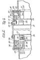
- the sieve device shown in figs. 1 through 4 comprise a frame, that is constructed from a number of horizontal beams 1, which rest by means of a number of legs 2 on the ground 3.
- a central drive shaft 4 is arranged, which is coupled on the lower side of the beams 1 with a gear box 5 that is suspended to the frame, on which gear box 5 an electrical drive motor 6 is connected.
- the main sieve surface 8 is fastened by means of a wheel 7.
- This main sieve surface 8 is in the shape of a truncated, hollow cone casing, of which the top is downwardly directed.
- the angle of inclination of the main sieve surface 8 with the horizontal is relatively small and can amount to about 10 to 20°.
- the perforations of the sieve surface 8 have in the shown embodiment a size of 7 to 8 mm, whereas those of the additional or auxiliary sieve surface 16 have a size of 4 to 5 mm.
- a composite, non perforate distributor cone 10 has been fastened by means of a central screw bolt 9, which distributor cone has the top angle upwardly directed.
- This cone 10 connects with its circumferential edge to the lower or main sieve surface 8, whereas the vertically displaceable, upper sieve 16 connects in the operative position to the higher placed part of the cone 10.
- the distributor cone 10 has been further provided around the outer circumference thereof with a number of spaced, triangular guide elements 13, which are welded with one side to the composite distributor cone 10, whereas the outwardly directed triangle side 14 makes a small angle with the vertical and acts as a guide means for the inner edge of a ring shaped plate 15.
- This ring shaped, horizontal plate 15 has been fastened on the inside of the additional or auxiliary sieve surface 16 that extends parallel to the main sieve surface 8 and can rest with a cylindrical, vertical circumferential edge 17 on the outer circumference of the main sieve surface 8, which can move itself with a small play over the support and sealing 18, which is fastened with a horizontal ring 1 ' 9 to the outer wall 20 of the housing of the sieve device.
- the lower end is fastened of a number of Z shaped support rods 21 spaced around the circumference, of which rods the upper end is suspended to a cylindrical support bushing 22 with a ring shaped, horizontally protruding upper flange 23.
- the cylindrical support bushing 22 with the horizontally protruding upper flange 23 rests on the upper end of a number of support shafts 24 spaced around the inner circumference thereof.
- These support shafts 24 each carry-viewed in an inward direction-a rotatable lift roll 25 and are then unrotatably fastened in a spacer ring 26 and carry at last at the inner end a rotatable guide roll 27.
- the lift rolls 25 are each displaceable in a corresponding, helically shaped slit 28 in a cylindrical lift bushing 29, which vertically mounted and can be driven with a reciprocating rotational movement for lifting and lowering respectively of the cylindrical support bushing 22 with the support rods 21, the ring shaped support plate 15 and the additional sieve surface 16 between the non-operative and the operative position.
- the rotating, reciprocating movement of the lift bushing 29 is obtained via a horizontally and outwardly protruding flange 32.
- a catch strip 33 is fastened, which is at both ends 34, 35 coupled with one end of a chain 36 which is stretched around a chain sprocket 37, that is fastened on a driven shaft 38 of an electrical motor 39 which is rotatable in two directions, that is suspended next to the housing 20.
- an operating boss 40 is mounted, for the alternative operation of two corresponding end switches 41, 42 which are fixedly arranged with a spacing along the track of the chain 36.
- These end switches are adapted for switching off the motor 39 at the end of the lift and lower movement respectively of the additional sieve surface 16 when reaching the non-operative and the operative position respectively of the additional sieve surface 16 when reaching the non-operative and the operative position respectively of the additional sieve surface 16.
- a pair of guide plates 43, 44 are fastened, which ensure that the operation of the switches always takes place when the operating boss 40 arrives at the guide plates.
- the lift device further comprises a number of support and guide rolls 46 that are spaced around the circumference of the lift bushing 29 and are fastened to the upper wall 45 of the device. These rolls 46 support the lower side of the outwardly extending upper flange 32 of the lift bushing 29.
- the support and guide rolls 46 have horizontal rotation shafts 54.
- the upper lid 47 of the sieve device that is fastened on the upper wall of the device by means of screw bolts 48 and a spacer ring 49, comprises a number of positioning and guide rolls 50 that are spaced around the circumference. These positioning and guide rolls 50 contact the inner side of the lift bushing 29, at the level of the outwardly protruding upper flange 32.
- the guide rolls 50 are rotatable around the vertical shafts 51, that are fastened in the upper lid 47 and are fixed by means of a closing ring 52 with a series of screw bolts 53.
- the horizontal rotation shafts 54 of the support rolls 46 extend substantially in the extension of the upper wall 45 of the device.
Landscapes
- Combined Means For Separation Of Solids (AREA)
- Gear Transmission (AREA)
- Disintegrating Or Milling (AREA)
Applications Claiming Priority (2)
| Application Number | Priority Date | Filing Date | Title |
|---|---|---|---|
| NL7907587 | 1979-10-12 | ||
| NL7907587A NL7907587A (nl) | 1979-10-12 | 1979-10-12 | Zeefinrichting voor het scheiden van een mengsel van deeltjesvormig materiaal in componenten van verschillende grootte. |
Publications (2)
| Publication Number | Publication Date |
|---|---|
| EP0027296A1 EP0027296A1 (en) | 1981-04-22 |
| EP0027296B1 true EP0027296B1 (en) | 1983-07-13 |
Family
ID=19834006
Family Applications (2)
| Application Number | Title | Priority Date | Filing Date |
|---|---|---|---|
| EP80200965A Expired EP0027296B1 (en) | 1979-10-12 | 1980-10-10 | A sieve device for separating a mixture of particulate material in components of different sizes |
| EP80200966A Expired EP0027297B1 (en) | 1979-10-12 | 1980-10-10 | Sieve device for separating a mixture of particulate material in components of different size |
Family Applications After (1)
| Application Number | Title | Priority Date | Filing Date |
|---|---|---|---|
| EP80200966A Expired EP0027297B1 (en) | 1979-10-12 | 1980-10-10 | Sieve device for separating a mixture of particulate material in components of different size |
Country Status (7)
| Country | Link |
|---|---|
| US (2) | US4293407A (da) |
| EP (2) | EP0027296B1 (da) |
| AU (2) | AU532314B2 (da) |
| CA (2) | CA1159406A (da) |
| DE (2) | DE3064146D1 (da) |
| DK (2) | DK148077C (da) |
| NL (1) | NL7907587A (da) |
Cited By (3)
| Publication number | Priority date | Publication date | Assignee | Title |
|---|---|---|---|---|
| US4583415A (en) * | 1982-03-24 | 1986-04-22 | C.L.M. Cooperatieve | Friction wheel transmission for driving a rotary sieve device |
| EP0278124A1 (en) * | 1987-02-07 | 1988-08-17 | Machinefabriek A. Wijnveen B.V. | A rotating sieving apparatus with a number of sieving surfaces each of which is subdivided into a number of concentric rings with reversible and continuously regulatable angular-velocities |
| NL1003257C2 (nl) * | 1996-06-03 | 1997-12-10 | Wijnveen Ede B V | Zeefinrichting met een zeefstand en een kortsluitstand. |
Families Citing this family (9)
| Publication number | Priority date | Publication date | Assignee | Title |
|---|---|---|---|---|
| DE3404297C2 (de) * | 1984-02-08 | 1986-04-17 | Philips Patentverwaltung Gmbh, 2000 Hamburg | Vorrichtung zum Antreiben eines Vibrationsteiles, insbesondere eines kleinen Haushaltsgerätes |
| DE3610772C1 (de) * | 1986-03-29 | 1987-06-04 | Philips Patentverwaltung | Kleines Haushaltsgeraet,das mittels eines Einphasensynchronmotors angetrieben ist |
| US4759262A (en) * | 1987-05-11 | 1988-07-26 | The Dow Chemical Company | Apparatus for restraining rotary motion of a motor component |
| GB9026030D0 (en) * | 1990-11-29 | 1991-01-16 | Ecc Int Ltd | A rotary screen device |
| US5620101A (en) * | 1994-12-06 | 1997-04-15 | Andela Tool And Machine, Inc. | Trommel separator clutch mechanism and system |
| US6612934B2 (en) * | 1999-11-09 | 2003-09-02 | Richard E. Foster, Sr. | Reaction control device |
| EP1394196A1 (en) * | 2002-08-16 | 2004-03-03 | Rohm And Haas Company | Resin for solid phase synthesis |
| US8869988B2 (en) * | 2008-05-08 | 2014-10-28 | M-I L.L.C. | Cooling and classifying apparatus for pelletized product processing |
| CN114798423A (zh) * | 2022-05-07 | 2022-07-29 | 浙江森友环保成套设备有限公司 | 一种防堵塞智能高效砂石分离机 |
Family Cites Families (17)
| Publication number | Priority date | Publication date | Assignee | Title |
|---|---|---|---|---|
| DE440697C (de) * | 1927-02-12 | Otto Wiencke | Umlaufendes Ringtellersieb | |
| US755330A (en) * | 1902-03-19 | 1904-03-22 | Sturtevant Mill Co | Shaking-screen. |
| US772860A (en) * | 1903-09-09 | 1904-10-18 | Enos A Wall | Separator. |
| US1173671A (en) * | 1913-03-29 | 1916-02-29 | John A Mckinlay | Rotary separator. |
| GB169117A (en) * | 1920-11-24 | 1921-09-22 | Nicholas Wladimir Akimoff | Improvements in means for supporting machinery to minimize transmitted vibration |
| US1805785A (en) * | 1924-08-25 | 1931-05-19 | Kelvinator Corp | Refrigerated food cabinet |
| US1993615A (en) * | 1932-03-14 | 1935-03-05 | James W Murry | Mounting of oscillating apparatus |
| US1976588A (en) * | 1932-09-23 | 1934-10-09 | Gen Electric | Method of balancing rotors |
| US2269245A (en) * | 1939-09-01 | 1942-01-06 | Rca Corp | Motor |
| US2353763A (en) * | 1942-12-04 | 1944-07-18 | Columbia Recording Corp | Thrust bearing |
| US2915181A (en) * | 1954-02-10 | 1959-12-01 | Topp Hereward Josep Betheridge | Apparatus for use in classifying or both classifying and drying loose material |
| FR1417522A (fr) * | 1964-02-21 | 1965-11-12 | Hein | Tamis combiné pour le traitement des produits, en particulier destiné aux bols de centrifuges |
| US3416660A (en) * | 1965-09-10 | 1968-12-17 | Karlstad Mekaniska Ab | Screens, particularly for wood chips |
| US3417868A (en) * | 1966-06-06 | 1968-12-24 | Harlan J. Donelson Jr. | Grain cleaner |
| US3989435A (en) * | 1974-11-15 | 1976-11-02 | Xerox Corporation | Apparatus for fabricating spherically shaped particles of small diameter |
| NL179709C (nl) * | 1976-05-24 | 1989-06-16 | Coop Landbouw Aan Verkoop | Werkwijze voor het door zeven afscheiden van gruis uit veevoederpersstukjesmateriaal, alsmede een zeefinrichting daarvoor. |
| FR2407026A1 (fr) * | 1977-10-26 | 1979-05-25 | United Wire Group Ltd | Crible de tamisage |
-
1979
- 1979-10-12 NL NL7907587A patent/NL7907587A/nl not_active Application Discontinuation
-
1980
- 1980-10-10 DK DK431180A patent/DK148077C/da active
- 1980-10-10 AU AU63145/80A patent/AU532314B2/en not_active Ceased
- 1980-10-10 DE DE8080200965T patent/DE3064146D1/de not_active Expired
- 1980-10-10 CA CA000362169A patent/CA1159406A/en not_active Expired
- 1980-10-10 EP EP80200965A patent/EP0027296B1/en not_active Expired
- 1980-10-10 US US06/196,089 patent/US4293407A/en not_active Expired - Lifetime
- 1980-10-10 DK DK431280A patent/DK153125C/da not_active IP Right Cessation
- 1980-10-10 CA CA000362168A patent/CA1145715A/en not_active Expired
- 1980-10-10 EP EP80200966A patent/EP0027297B1/en not_active Expired
- 1980-10-10 US US06/196,090 patent/US4313823A/en not_active Expired - Lifetime
- 1980-10-10 AU AU63146/80A patent/AU533097B2/en not_active Ceased
- 1980-10-10 DE DE8080200966T patent/DE3068615D1/de not_active Expired
Cited By (4)
| Publication number | Priority date | Publication date | Assignee | Title |
|---|---|---|---|---|
| US4583415A (en) * | 1982-03-24 | 1986-04-22 | C.L.M. Cooperatieve | Friction wheel transmission for driving a rotary sieve device |
| EP0278124A1 (en) * | 1987-02-07 | 1988-08-17 | Machinefabriek A. Wijnveen B.V. | A rotating sieving apparatus with a number of sieving surfaces each of which is subdivided into a number of concentric rings with reversible and continuously regulatable angular-velocities |
| NL1003257C2 (nl) * | 1996-06-03 | 1997-12-10 | Wijnveen Ede B V | Zeefinrichting met een zeefstand en een kortsluitstand. |
| EP0811431A1 (en) * | 1996-06-03 | 1997-12-10 | Wijnveen Ede B.V. | Sieving device with sieving position and bypass position |
Also Published As
| Publication number | Publication date |
|---|---|
| US4293407A (en) | 1981-10-06 |
| DK153125C (da) | 1988-11-14 |
| DE3068615D1 (en) | 1984-08-23 |
| DK431180A (da) | 1981-04-13 |
| AU6314680A (en) | 1981-04-16 |
| CA1145715A (en) | 1983-05-03 |
| EP0027296A1 (en) | 1981-04-22 |
| EP0027297B1 (en) | 1984-07-18 |
| EP0027297A1 (en) | 1981-04-22 |
| DK148077B (da) | 1985-02-25 |
| DK153125B (da) | 1988-06-20 |
| US4313823A (en) | 1982-02-02 |
| CA1159406A (en) | 1983-12-27 |
| AU533097B2 (en) | 1983-10-27 |
| DK148077C (da) | 1985-07-29 |
| NL7907587A (nl) | 1981-04-14 |
| DE3064146D1 (en) | 1983-08-18 |
| AU6314580A (en) | 1981-04-16 |
| DK431280A (da) | 1981-04-13 |
| AU532314B2 (en) | 1983-09-22 |
Similar Documents
| Publication | Publication Date | Title |
|---|---|---|
| EP0027296B1 (en) | A sieve device for separating a mixture of particulate material in components of different sizes | |
| KR100473721B1 (ko) | 원심 펠릿 건조기 | |
| US4671666A (en) | Mixing device | |
| US3945537A (en) | Discharge device for a bunker | |
| US2430203A (en) | Material handling bin structure | |
| US3768628A (en) | Elevator-hopper-feeder-assembly | |
| CA1318284C (en) | Rotating ring disc slot screen | |
| US4436432A (en) | Kneading machine | |
| US3833118A (en) | Grain cleaning device | |
| JP2002336729A (ja) | 回転網ドラム式ゴミ分別装置 | |
| US4159053A (en) | Grain distributor | |
| US3957629A (en) | Adjustable air classifier drum and conveyor | |
| US4220526A (en) | Sizing screens and feeder devices therefor | |
| CN207412900U (zh) | 具有筛选与过滤双重功能的化工过滤装置 | |
| US3295232A (en) | Spiral earth removing blades and rotary cutters therefor | |
| GB2239824A (en) | Screening machine for rock | |
| DE2651099A1 (de) | Schwingzentrifuge zum entwaessern von feinkoernigem gut | |
| US2354096A (en) | Means for shelling eggs | |
| SU1400672A1 (ru) | Вибрационное сито | |
| US4308135A (en) | Sizing screens | |
| CN220670014U (zh) | 一种稻谷加工用烘干装置 | |
| CN111822333B (zh) | 一种用于颗粒状物料的筛选装置 | |
| SU1738385A1 (ru) | Сепаратор вороха | |
| US4244823A (en) | Centrifugal basket valve mechanism | |
| SU563195A1 (ru) | Барабанное сито |
Legal Events
| Date | Code | Title | Description |
|---|---|---|---|
| PUAI | Public reference made under article 153(3) epc to a published international application that has entered the european phase |
Free format text: ORIGINAL CODE: 0009012 |
|
| AK | Designated contracting states |
Designated state(s): BE DE FR GB IT NL SE |
|
| 17P | Request for examination filed |
Effective date: 19810820 |
|
| ITF | It: translation for a ep patent filed | ||
| GRAA | (expected) grant |
Free format text: ORIGINAL CODE: 0009210 |
|
| AK | Designated contracting states |
Designated state(s): BE DE FR GB IT NL SE |
|
| RAP2 | Party data changed (patent owner data changed or rights of a patent transferred) |
Owner name: MACHINEFABRIEK A. WIJNVEEN B.V. Owner name: COOEPERATIEVE LANDBOUW AAN- EN VERKOOPCOMBINATIE B |
|
| REF | Corresponds to: |
Ref document number: 3064146 Country of ref document: DE Date of ref document: 19830818 |
|
| ET | Fr: translation filed | ||
| PLBE | No opposition filed within time limit |
Free format text: ORIGINAL CODE: 0009261 |
|
| STAA | Information on the status of an ep patent application or granted ep patent |
Free format text: STATUS: NO OPPOSITION FILED WITHIN TIME LIMIT |
|
| 26N | No opposition filed | ||
| PGFP | Annual fee paid to national office [announced via postgrant information from national office to epo] |
Ref country code: SE Payment date: 19921023 Year of fee payment: 13 |
|
| ITTA | It: last paid annual fee | ||
| PG25 | Lapsed in a contracting state [announced via postgrant information from national office to epo] |
Ref country code: SE Effective date: 19931011 |
|
| EUG | Se: european patent has lapsed |
Ref document number: 80200965.4 Effective date: 19940510 |
|
| PGFP | Annual fee paid to national office [announced via postgrant information from national office to epo] |
Ref country code: FR Payment date: 19980922 Year of fee payment: 19 |
|
| PGFP | Annual fee paid to national office [announced via postgrant information from national office to epo] |
Ref country code: BE Payment date: 19981001 Year of fee payment: 19 |
|
| PGFP | Annual fee paid to national office [announced via postgrant information from national office to epo] |
Ref country code: GB Payment date: 19981002 Year of fee payment: 19 |
|
| PGFP | Annual fee paid to national office [announced via postgrant information from national office to epo] |
Ref country code: DE Payment date: 19981201 Year of fee payment: 19 |
|
| PG25 | Lapsed in a contracting state [announced via postgrant information from national office to epo] |
Ref country code: GB Free format text: LAPSE BECAUSE OF NON-PAYMENT OF DUE FEES Effective date: 19991010 |
|
| PGFP | Annual fee paid to national office [announced via postgrant information from national office to epo] |
Ref country code: NL Payment date: 19991026 Year of fee payment: 20 |
|
| PG25 | Lapsed in a contracting state [announced via postgrant information from national office to epo] |
Ref country code: BE Free format text: LAPSE BECAUSE OF NON-PAYMENT OF DUE FEES Effective date: 19991031 |
|
| BERE | Be: lapsed |
Owner name: MACHINEFABRIEK A. WIJNVEEN B.V. Effective date: 19991031 Owner name: COOPERATIEVE LANDBOUW AAN- EN VERKOOPCOMBINATIE B. Effective date: 19991031 |
|
| GBPC | Gb: european patent ceased through non-payment of renewal fee |
Effective date: 19991010 |
|
| PG25 | Lapsed in a contracting state [announced via postgrant information from national office to epo] |
Ref country code: FR Free format text: LAPSE BECAUSE OF NON-PAYMENT OF DUE FEES Effective date: 20000630 |
|
| PG25 | Lapsed in a contracting state [announced via postgrant information from national office to epo] |
Ref country code: DE Free format text: LAPSE BECAUSE OF NON-PAYMENT OF DUE FEES Effective date: 20000801 |
|
| REG | Reference to a national code |
Ref country code: FR Ref legal event code: ST |
|
| PG25 | Lapsed in a contracting state [announced via postgrant information from national office to epo] |
Ref country code: NL Free format text: LAPSE BECAUSE OF EXPIRATION OF PROTECTION Effective date: 20001010 |
|
| NLV7 | Nl: ceased due to reaching the maximum lifetime of a patent |
Effective date: 20001010 |