EP0026425A2 - Steuervorrichtung für eine Rundstrickmaschine, insbesondere eine Strumpfstrickmaschine - Google Patents
Steuervorrichtung für eine Rundstrickmaschine, insbesondere eine Strumpfstrickmaschine Download PDFInfo
- Publication number
- EP0026425A2 EP0026425A2 EP80105686A EP80105686A EP0026425A2 EP 0026425 A2 EP0026425 A2 EP 0026425A2 EP 80105686 A EP80105686 A EP 80105686A EP 80105686 A EP80105686 A EP 80105686A EP 0026425 A2 EP0026425 A2 EP 0026425A2
- Authority
- EP
- European Patent Office
- Prior art keywords
- machine
- programming unit
- knitting
- electronic programming
- members
- Prior art date
- Legal status (The legal status is an assumption and is not a legal conclusion. Google has not performed a legal analysis and makes no representation as to the accuracy of the status listed.)
- Withdrawn
Links
Images


Classifications
-
- D—TEXTILES; PAPER
- D04—BRAIDING; LACE-MAKING; KNITTING; TRIMMINGS; NON-WOVEN FABRICS
- D04B—KNITTING
- D04B15/00—Details of, or auxiliary devices incorporated in, weft knitting machines, restricted to machines of this kind
- D04B15/66—Devices for determining or controlling patterns ; Programme-control arrangements
- D04B15/68—Devices for determining or controlling patterns ; Programme-control arrangements characterised by the knitting instruments used
- D04B15/78—Electrical devices
-
- D—TEXTILES; PAPER
- D04—BRAIDING; LACE-MAKING; KNITTING; TRIMMINGS; NON-WOVEN FABRICS
- D04B—KNITTING
- D04B15/00—Details of, or auxiliary devices incorporated in, weft knitting machines, restricted to machines of this kind
- D04B15/66—Devices for determining or controlling patterns ; Programme-control arrangements
Definitions
- This invention relates to a control device for a circular knitting machine, in particular a hose knitting machine.
- the various operational members of a circular knitting machine of this general type are currently controlled by the machine main chain as a function of the product to be obtained.
- the main chain is advanced stepwise at a rate which is related to the needle cylinder(s) rpm, and is provided with bosses or raised portions, often having varied heights, which are engaged by pawls or other control levers, the raising whereof causes, through intervening elements, determined members of the machine to become operative such as the ones advancing the main drum, driving the stitch-adjusting unit, switching the yarn feeding fingers, etc.
- One full revolution of the chain usually results in a complete knitting cycle, e.g. a complete hose knitting cycle.
- This invention sets out to overcome the cited drawbacks by providing a control device for a circular knitting machine, in particular a hose knitting machine, which is of simpler construction than conventional ones, affords a significant simplification of the machine design, and is readily adaptable for different knitworks.
- the device as indicated has an overall size which is considerably smaller than conventional . chains and associated members, and can be incorporated to circular knitting machines for a very large variety of knitworks.
- the device according to the invention has a structure such as to reduce the amount of manual work involved in the event of failure to reset the control device, to thus reduce the downtime and increase the machine output.
- this device enables the knitting cycle of a given circular knitting machine incorporating the device to be modified for a limited constructional and labor effort.
- a control device for a circular knitting machine in particular a hose knitting machine, adapted for controlling operational machine members
- the device being characterized in that it comprises an electronic storage-type programming unit effective to produce control pulses in the sequence of operations required by the knitting process, and at least one electromechanical transducer for converting the control pulses generated by said electronic programming unit into mechanical movements for controlling said operational machine members.
- the knitwork process programming and adaptation for different knitworks are made much easier.
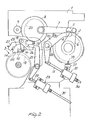
- a circular knitting machine in particular a double cylinder hose knitting machine, has , preferably on the side portion 1 whereat the main chain is normally arranged, the actuating members for the main drum 2 and part of the actuating members for the stitch-adjusting unit 3, which is accommodated in the machine inside.
- the main drum 2 comprises, in a manner known per se, a peripheral tooth formation 4, and is advanced stepwise by a pawl 5 pivoted to one end of a crank lever 6 coaxial with the drum 2.
- the pawl 5 is also pivoted to one end of a connecting rod 7 which is driven back and forth by a gear wheel 8, whereto the connecting rod 7 is pivoted at an eccentric position on the other end thereof.
- the gear wheel 8 is meshingly driven by a pinion gear 9 which derives its motion from the machine main drive, not shown.
- the pawl 5 is held normally disengaged from the tooth formation or serration 4 by an arcuate lever 10, which is pivoted at an intermediate point thereof to the side portion 1 and is provided with a guiding surface 10a wherealong the pawl 5 slides when disengaged from the serration 4.
- the arcuate lever 10 is displaceable between a position whereat it raises the pawl 5 above the teeth of the serration 4 ( Figure 2), thus preventing the drum 2 from being advanced, and a position whereat it allows the pawl 5 to engage in between the teeth of the serration 4 ( Figure 1), and hence the advancement of the drum 2.
- the movement between said two positions is effected through a linkage element 11, pivoted to the lever 10 at the opposite end to that provided with the guiding surface 10a.
- the linkage element or tie 11 is rigid with a small piston movable in a pneumatic or hydraulic cylinder 12. The piston is actuated under control by the control device according to the invention, as will be explained hereinafter.
- FIGS 1 and 2 illustrate, to the stitch-adjusting unit 3, which controls in a manner known per se the progressive and local narrowing of the stitches by a relative axial displacement between the needle cylinder and cam ring, there is rigidly attached a cam 13 the profile whereof is designed to match the desired amount of narrowing during the knitting of the product.
- Rigid with the cam 13 is also a ratchet or sawtooth wheel 14; which is caused to advance by a pawl 15 pivoted to one end of an arm 16, the other end whereof is rigid with a yoke element 17, in turn pivoted for free rotation about an axle 18 extending parallel to the axis of the drum 2.
- the element 17 carries a small roller 19 which follows a cam 20 rotating with the gear wheel 8.
- One revolution of the latter results in one or more oscillations of the element 17 about its axle 18, and hence in the advancement of the cam 13 through one or more steps.
- one complete revolution of the cam 13 corresponds to the knitting of one hose or other finished product.
- a hooked end can be received of a lever 21 pivoted at an intermediate point to the side portion 1 about a parallel axis to the axle 18 and at the opposite end to a linkage member or tie 22.
- the latter is rigid with a small piston slidable in a pneumatic or hydraulic cylinder 23, preferably similar to the cylinder 12.
- the cam 13 is followed by the hook 24 of a small lever 25 pivoted at 26 to a lever 27 the free end whereof is supported by the lever 25 with relative adjustment provisions (Figure 3).
- the lever 27 is pivoted to the stationary structure of the machine, at 28. The raising and dropping movements of the lever 27 in riding the profile of the cam 13 produce, in a manner known per se, the axial relative displacement between the needle cylinder and the cam ring, to result in different length stitches.
- Each pneumatic cylinder 12 and 23 includes ( Figure 4) a small piston 28 biased by a spring 29 to move into a rest position close to the intake end of the cylinder 12 or 23, whereto a supply conduit 30, respectively 31, is connected.
- Each conduit 30,31 is connected to a respective solenoid valve 32 in the bank 33 of solenoid valves shown in Figure 10.
- the programmed actuation of the solenoid valves by the electronic programming unit, to be described hereinafter, results in the admission of pressurized fluid to the cylinder 12 and/or 23, and therefore, in the displacement of the respective small pistons 28 and members connected thereto between the two positions described hereinabove, depending on knitting requirements.
- the pressurized fluid is fed to the solenoid valve-bank 33 through a conduit 34 from a source of fluid under pressure, not shown.
- the fluid is discharged from the conduits 30,31 through openings or ports 35 in the solenoid valves.
- a machine incorporating the control device of this invention further comprises members for sensing the rpm of the needle cylinder(s) to drive the electronic programming unit.
- a disk 36 is provided rigid with a rotating member 37, which is driven rotatively at a 1:1 ratio with the (lower) needle cylinder 38.
- the disk 36 has a radial pin 39 which moves between a pair of photoelectric members or phototransistors 40. Each passage of the pin 39 will cause the phototransistors 40 to generate a pulse, which is then sent to the electronic programming unit 41 ( Figures 11,12). Thus, there will occur a pulse for each revolution of the cylinder, that is for each knitting course.
- control device of this invention also lends itself to electromechanically controlling the machine needle selecting devices.
- An exemplary embodiment is shown in Figures 7,8 and 9.
- the needle selecting device comprises, in this instance, a stationary supporting structure 42 having slidable therein, in a radial direction to the needle cylinder 38, selection slides 43 adapted for interfering with pattern butts 44 of jacks 45, which control in a conventional manner the needles (not shown).
- the jacks 45 as selectively urged by one of the slides 43 into the position shown in Figure 7, ride a cam 46 to bring the respective needles to knit. The contrary occurs when the jacks are not pushed to the position shown in Figure 7; in this case, they will pass at a low position externally to the cam 46.
- a pneumatic actuating device 47 comprising a cylindrical chamber 48, formed in the supporting structure 42, and a small piston 49 arranged to slide in said chamber.
- the piston 49 has a rod 50 which is passed through a closure element 51 of the chamber 48, on the same side as the cylinder 38, and is effective to engage a respective slide 43.
- a conduit 52 for a fluid under pressure From the opposite end of the chamber 48, there extends a conduit 52 for a fluid under pressure, the conduit terminating into one solenoid valve 32 in the bank 33.
- the actuating devices 47 of adjacent slides 43 are offset in the structure 42.
- Each slide 43 is subjected to the action of a biasing spring 53, one end whereof is secured to the slide 43 and the other to the stationary structure 42.
- FIG. 9 illustrates a modified embodiment of the selection device just described.
- the pneumatic actuating device 47 has been replaced with an electromagnet 54, program-wise energized directly from the electronic programming unit and provided with a rod-like movable anchor 55, adapted for engaging a respective slide 43.
- the electromagnets 54 are offset on the structure 42 for space reasons.
- control pulses for actuating the slides in succession by means of a photoelectric device of the same type as discussed with reference to Figures 5 and 6, which comprises a rotating pin and a number of phototransistors arrayed in succession along the path of the rotating pin, each phototransistor being associated with one slide or set of slides.
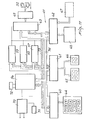
- the electronic programming unit 41 comprises essentially a microprocessor 56, a pair of random access memories (RAM) 57,58, a read-only memory (ROM) 59, and a number of peripheral interface adapters (PIA) 60,61,62,and 63. Also provided is a keyboard 64 for writing in the program, which is connected to the unit through the adapter 60, while two displays 65,66 enable the machine revolutions and the spared number of revolutions (when a certain number of operations are to be reiterated identically for a given number of machine revolutions, in which case the preceding program is maintained for the required number of revolutions before fresh knitting operations are resumed), respectively, to be read visually, the displays being connected to the unit through the adapter 61.
- RAM random access memories
- ROM read-only memory
- PDA peripheral interface adapters
- the control output of the unit 41 is represented by the adapter 63, which controls a number of amplifiers 69, one for each machine member or unit to be controlled, whereto respective solenoid valves 31 are connected.
- the unit 41 is fed through a feeder 70 or by a battery 71, and the microprocessor 56 is driven by a crystal controlled oscillator 72.
- the components of the electronic programming unit are respectively connected through connections 73 and 74, the former being the data bus and the latter the address bus.
- the microprocessor 56 processes and checks the data input from the machine, as well as those written with the keyboard in accordance with the machine operational program, to compare them each time with those contained in the various memories.
- the read-only memory 59 stores the main program, which is then adapted, as the case may be, to the requirements of a specific knitting operation by means of the random access memories 57,58.
- the unit is made extremely versatile and suitable for a large number of operational programs.
- RAM random access memories
- ROM read-only memory
- TMS 2708 JL type by Texas Instruments
- microprocessor 56 may be of the MC 6800 type by Motorola, Inc.
- peripheral interface adapters (PIA) 60,61,62,63 may be of the MC 6820 type, also by Motorola, Inc..
- the operational program will be prepared with due consideration to the various functions to be performed by the machine at each revolution of the needle cylinder(s) (main drum advancing, stitch-adjusting unit advancing, needle selecting, etc.). Such functions, in actual practice, will be each controlled through one solenoid valve 31. Therefore, the matter is one of actuating and de-actuating the respective solenoid valve 31 at a given time during one or more machine revolutions.
- the keyboard 64 After identifying the various revolutions of the machine with progressive numbers, one dials on the keyboard 64, at each program step (corresponding to the step of the traditional mechanical chain) the number corresponding to the solenoid valve(s) associated with the mechanical members which are to complete certain functions during that particular step, and this until the knitting cycle is completed, to thus accomplish the programming of the electronic unit 40. Thus, the unit is made ready to operate.
- the keyboard may also include reset, cancellation, fast and unit advance keys, etc.
- the programming unit can be supplied with machine control data from a magnetic tape, e.g. as contained in a magnetic tape cassette.
- a magnetic tape cassette e.g. as contained in a magnetic tape cassette.
- the programming unit according to this invention can also be utilized to change the machine speed.
- the adapter 49 would energize or de-energize, in accordance with the change to be effected (switching from medium speed to a higher or lower speed, and viceversa), a relay, which controls the motor, e.g. through a full wave TRIAC, and applies a voltage to respective windings in the motor or removes it therefrom, to de-energize them.
- Figure 12 illustrates diagrammatically one embodiment of the electronic programming unit. This is provided on a printed circuit card, including the various components discussed in the foregoing.
- the reference numerals 75,76 designate terminals for connecting the unit to the power supply and to the utilizing circuits.
- FIG. 1 and 2 moreover, there is shown a microswitch 77, which is actuated by a pin or peg 78 rigid with the main drum 2.
- the microswitch 77 as suitably connected to the programmer 41, serves the function of resetting the programmer upon completion of one complete revolution of the main drum 2, thereby initiating a fresh knitting cycle.
- control device considerably simplifies, from the structural standpoint, the side member or side portion of the machine, which normally carries, in addition to the mechanical main chain, several linkages and other moving mechanical members. Also greatly simplified is the machine setting operation following a failure and discarding of the product.
- the zeroing of the electronic programming unit is accomplished instantaneously, e.g. by means of a specially provided key on the keyboard 64, while it also becomes possible, in the case of a single cylinder machine for knitting heel-less stockings or hoses, to achieve an automatic and continuous advancement of the main drum 2, under the action of the pawl 5, at a high speed to the zero position.
- the main drum shall have to be zeroed manually, although the advantage is retained that no mechanical chain must be zeroed manually.
- the inventive device moreover, lends itself to a quick change of the knitting program. It is in fact possible to store several programs, and in conformity with the selected program, to push a key down to start a new knitting machine program. Alternatively, the magnetic tape cassette may be replaced which supplies the knitting data to the electronic unit 41.
- the entire electronic unit can be contained in a very modest space, thereby, when it is considered that many linkages are eliminated from the machine incorporating this control device, the overall dimensions of the machine can be reduced considerably.
- electromagnets may be provided, under direct control from the respective amplifiers 69 of the electronic programming unit 41, such as to eliminate altogether the solenoid valves 31 and related lines for the pressurized fluid.
- the device described hereinabove can be applied both to single cylinder machines and double cylinder ones, or cylinder and dial machines.
Landscapes
- Engineering & Computer Science (AREA)
- Textile Engineering (AREA)
- Knitting Machines (AREA)
Applications Claiming Priority (2)
| Application Number | Priority Date | Filing Date | Title |
|---|---|---|---|
| IT26157/79A IT1123396B (it) | 1979-10-01 | 1979-10-01 | Dispositivo di comando in una macchina circolare per maglieria,in particolare una macchina per calze |
| IT2615779 | 1979-10-01 |
Publications (2)
| Publication Number | Publication Date |
|---|---|
| EP0026425A2 true EP0026425A2 (de) | 1981-04-08 |
| EP0026425A3 EP0026425A3 (de) | 1981-05-13 |
Family
ID=11218777
Family Applications (1)
| Application Number | Title | Priority Date | Filing Date |
|---|---|---|---|
| EP80105686A Withdrawn EP0026425A3 (de) | 1979-10-01 | 1980-09-22 | Steuervorrichtung für eine Rundstrickmaschine, insbesondere eine Strumpfstrickmaschine |
Country Status (3)
| Country | Link |
|---|---|
| EP (1) | EP0026425A3 (de) |
| JP (1) | JPS5679745A (de) |
| IT (1) | IT1123396B (de) |
Cited By (14)
| Publication number | Priority date | Publication date | Assignee | Title |
|---|---|---|---|---|
| FR2508192A1 (fr) * | 1981-06-22 | 1982-12-24 | Superba Sa | Mini-ordinateur de tricotage donnant des instructions de tricotage |
| EP0073745A1 (de) * | 1981-09-02 | 1983-03-09 | Officine Savio S.p.A. | Fadenliefer-Ringelvorrichtung für Rundstrickmaschinen |
| EP0147139A2 (de) * | 1983-12-19 | 1985-07-03 | Watanabe Kutsushita Kogyo Co., Ltd. | Jacquard-Rundstrickmaschine |
| US4527402A (en) * | 1982-09-29 | 1985-07-09 | Rampon Products, Inc. | Program-controlled knitting machine, method and products thereof |
| GB2151044A (en) * | 1983-11-02 | 1985-07-10 | Sangiacomo Off Mec | Regulating the speed and position of hosiery and knitting machines |
| US4567737A (en) * | 1982-05-10 | 1986-02-04 | Lonati S.P.A. | Device for adjusting loop density in a circular knitting machine |
| EP0259123A2 (de) * | 1986-08-28 | 1988-03-09 | Draper Corporation | Rundstrickmaschine |
| EP0305770A1 (de) * | 1987-08-14 | 1989-03-08 | SIPRA Patententwicklungs- und Beteiligungsgesellschaft mbH | Einstellvorrichtung für Nadelauswahleinrichtungen mehrsystemiger Rundstrickmaschinen |
| EP0533088A2 (de) * | 1991-09-19 | 1993-03-24 | LONATI S.p.A. | Fadenführervorrichtung für Rundstrickmaschinen, insbesonderes für Doppel-Zylinder-Rundstrickmaschinen für die Herstellung von Socken und Strümpfen |
| EP0420836B1 (de) * | 1986-07-07 | 1995-02-15 | B.T.S.R. International S.p.A. | Signalüberwachungsverfahren |
| EP0722007A1 (de) * | 1995-01-13 | 1996-07-17 | Precision Fukuhara Works, Ltd | Rundstrickmaschine mit verbessertem Nadelauswahlmechanismus |
| WO1997031144A1 (en) * | 1996-02-24 | 1997-08-28 | The Rhd Company Limited | Sinker drive mechanism |
| EP1536051A1 (de) | 2003-11-27 | 2005-06-01 | Pai Lung Machinery Mill Co. Ltd. | Mikrosteuereinrichtung für Rundstrickmaschinen |
| CN107794639A (zh) * | 2017-11-24 | 2018-03-13 | 新昌县振兴纺织机械有限公司 | 一种具有生克罩调节功能的隐形袜织袜机提花装置 |
Families Citing this family (3)
| Publication number | Priority date | Publication date | Assignee | Title |
|---|---|---|---|---|
| JPS59150148A (ja) * | 1983-02-16 | 1984-08-28 | 富士電機株式会社 | 編機用電子柄出装置 |
| JPS6260281U (de) * | 1985-09-30 | 1987-04-14 | ||
| JPH047197Y2 (de) * | 1985-09-30 | 1992-02-26 |
Citations (10)
| Publication number | Priority date | Publication date | Assignee | Title |
|---|---|---|---|---|
| FR1254653A (fr) * | 1960-04-15 | 1961-02-24 | Electro Hydraulics Ltd | Dispositif de positionnement hydraulique permettant de placer, dans un certain nombre de positions uniformément espacées, un organe de sortie |
| DE2311710A1 (de) * | 1972-03-09 | 1973-09-27 | Wildt Mellor Bromley Ltd | Vorrichtung zur steuerung von strickmaschinen |
| US3901050A (en) * | 1973-04-02 | 1975-08-26 | Rome Knitting Mills Inc | Automatic knitting machine |
| US3945224A (en) * | 1973-07-30 | 1976-03-23 | Billi, S.P.A. | Control system for circular knitting machines and the like |
| US3969912A (en) * | 1973-07-12 | 1976-07-20 | Elitex, Zavody Textilniho Strojirenstvi Generalni Reditelstvi | Patterning memory for circular knitting machine |
| DE2608862A1 (de) * | 1975-03-22 | 1976-10-07 | Elitex Zavody Textilniho | Rundstrickmaschine |
| DE2716651A1 (de) * | 1976-06-14 | 1977-12-15 | Herstal Sa | Programmierverfahren fuer strickmaschinen und vorrichtungen fuer die durchfuehrung desselben |
| US4114405A (en) * | 1977-10-06 | 1978-09-19 | Empisal Knitmaster Luxembourg S.A. | Control unit for a hand knitter |
| DE2841671A1 (de) * | 1977-09-30 | 1979-04-05 | Elitex Zavody Textilniho | Schaltwerk fuer rundstrickmaschinen |
| FR2438107A1 (fr) * | 1978-10-05 | 1980-04-30 | Matec Spa | Systeme electronique de memorisation de donnees et de commande de metiers a bas de femmes |
-
1979
- 1979-10-01 IT IT26157/79A patent/IT1123396B/it active
-
1980
- 1980-09-22 EP EP80105686A patent/EP0026425A3/de not_active Withdrawn
- 1980-09-30 JP JP13536980A patent/JPS5679745A/ja active Pending
Patent Citations (10)
| Publication number | Priority date | Publication date | Assignee | Title |
|---|---|---|---|---|
| FR1254653A (fr) * | 1960-04-15 | 1961-02-24 | Electro Hydraulics Ltd | Dispositif de positionnement hydraulique permettant de placer, dans un certain nombre de positions uniformément espacées, un organe de sortie |
| DE2311710A1 (de) * | 1972-03-09 | 1973-09-27 | Wildt Mellor Bromley Ltd | Vorrichtung zur steuerung von strickmaschinen |
| US3901050A (en) * | 1973-04-02 | 1975-08-26 | Rome Knitting Mills Inc | Automatic knitting machine |
| US3969912A (en) * | 1973-07-12 | 1976-07-20 | Elitex, Zavody Textilniho Strojirenstvi Generalni Reditelstvi | Patterning memory for circular knitting machine |
| US3945224A (en) * | 1973-07-30 | 1976-03-23 | Billi, S.P.A. | Control system for circular knitting machines and the like |
| DE2608862A1 (de) * | 1975-03-22 | 1976-10-07 | Elitex Zavody Textilniho | Rundstrickmaschine |
| DE2716651A1 (de) * | 1976-06-14 | 1977-12-15 | Herstal Sa | Programmierverfahren fuer strickmaschinen und vorrichtungen fuer die durchfuehrung desselben |
| DE2841671A1 (de) * | 1977-09-30 | 1979-04-05 | Elitex Zavody Textilniho | Schaltwerk fuer rundstrickmaschinen |
| US4114405A (en) * | 1977-10-06 | 1978-09-19 | Empisal Knitmaster Luxembourg S.A. | Control unit for a hand knitter |
| FR2438107A1 (fr) * | 1978-10-05 | 1980-04-30 | Matec Spa | Systeme electronique de memorisation de donnees et de commande de metiers a bas de femmes |
Cited By (22)
| Publication number | Priority date | Publication date | Assignee | Title |
|---|---|---|---|---|
| FR2508192A1 (fr) * | 1981-06-22 | 1982-12-24 | Superba Sa | Mini-ordinateur de tricotage donnant des instructions de tricotage |
| EP0073745A1 (de) * | 1981-09-02 | 1983-03-09 | Officine Savio S.p.A. | Fadenliefer-Ringelvorrichtung für Rundstrickmaschinen |
| US4567737A (en) * | 1982-05-10 | 1986-02-04 | Lonati S.P.A. | Device for adjusting loop density in a circular knitting machine |
| US4527402A (en) * | 1982-09-29 | 1985-07-09 | Rampon Products, Inc. | Program-controlled knitting machine, method and products thereof |
| GB2151044A (en) * | 1983-11-02 | 1985-07-10 | Sangiacomo Off Mec | Regulating the speed and position of hosiery and knitting machines |
| US4841748A (en) * | 1983-12-19 | 1989-06-27 | Watanabe Kutsushita Kogyo Co., Ltd. | Jacquard circular knitting machine |
| EP0147139A2 (de) * | 1983-12-19 | 1985-07-03 | Watanabe Kutsushita Kogyo Co., Ltd. | Jacquard-Rundstrickmaschine |
| EP0147139A3 (en) * | 1983-12-19 | 1985-08-21 | Watanabe Kutsushita Kogyo Ltd. | Jacquard circular knitting machine |
| EP0420836B1 (de) * | 1986-07-07 | 1995-02-15 | B.T.S.R. International S.p.A. | Signalüberwachungsverfahren |
| EP0259123A3 (en) * | 1986-08-28 | 1990-07-18 | Draper Corporation | Circular weft knitting machine |
| EP0259123A2 (de) * | 1986-08-28 | 1988-03-09 | Draper Corporation | Rundstrickmaschine |
| EP0305770A1 (de) * | 1987-08-14 | 1989-03-08 | SIPRA Patententwicklungs- und Beteiligungsgesellschaft mbH | Einstellvorrichtung für Nadelauswahleinrichtungen mehrsystemiger Rundstrickmaschinen |
| EP0533088A2 (de) * | 1991-09-19 | 1993-03-24 | LONATI S.p.A. | Fadenführervorrichtung für Rundstrickmaschinen, insbesonderes für Doppel-Zylinder-Rundstrickmaschinen für die Herstellung von Socken und Strümpfen |
| EP0533088A3 (en) * | 1991-09-19 | 1993-04-21 | Lonati S.R.L. | Thread feed unit for circular knitting machines, in particular for double-cylinder knitting machines for manufacturing socks and stockings |
| US5237841A (en) * | 1991-09-19 | 1993-08-24 | Lonati S.R.L. | Thread feed unit using pneumatic actuators |
| EP0722007A1 (de) * | 1995-01-13 | 1996-07-17 | Precision Fukuhara Works, Ltd | Rundstrickmaschine mit verbessertem Nadelauswahlmechanismus |
| US5647230A (en) * | 1995-01-13 | 1997-07-15 | Precision Fukuhara Works, Ltd. | Needle selection mechanism for circular knitting machine |
| WO1997031144A1 (en) * | 1996-02-24 | 1997-08-28 | The Rhd Company Limited | Sinker drive mechanism |
| US6119488A (en) * | 1996-02-24 | 2000-09-19 | The Rhd Company Limited | Piston assembly drive for knitting machine actuating sinkers |
| EP1536051A1 (de) | 2003-11-27 | 2005-06-01 | Pai Lung Machinery Mill Co. Ltd. | Mikrosteuereinrichtung für Rundstrickmaschinen |
| CN107794639A (zh) * | 2017-11-24 | 2018-03-13 | 新昌县振兴纺织机械有限公司 | 一种具有生克罩调节功能的隐形袜织袜机提花装置 |
| CN107794639B (zh) * | 2017-11-24 | 2023-06-23 | 浙江专博纺织机械有限公司 | 一种具有生克罩调节功能的隐形袜织袜机提花装置 |
Also Published As
| Publication number | Publication date |
|---|---|
| IT1123396B (it) | 1986-04-30 |
| EP0026425A3 (de) | 1981-05-13 |
| JPS5679745A (en) | 1981-06-30 |
| IT7926157A0 (it) | 1979-10-01 |
Similar Documents
| Publication | Publication Date | Title |
|---|---|---|
| EP0026425A2 (de) | Steuervorrichtung für eine Rundstrickmaschine, insbesondere eine Strumpfstrickmaschine | |
| US3232079A (en) | Circular knitting machine | |
| US3895355A (en) | Pattern control system | |
| US4445447A (en) | Tufting machine apparatus | |
| US4254718A (en) | Method and means of tufting | |
| GB1473344A (en) | Control apparatus for a warp knitting machine | |
| GB653673A (en) | Improvements in or relating to knitting machines | |
| US4099390A (en) | Selection device for the needles of a knitting machine | |
| US4138955A (en) | Stitch length control for electronic sewing machine | |
| US3916646A (en) | Electronic patterning process for a knitting machine | |
| US2225842A (en) | Circular knitting machine | |
| US4007607A (en) | Method and apparatus for knitting patterned sliver high pile fabric | |
| US2436468A (en) | Pattern mechanism for knitting machines | |
| US4448047A (en) | Embroidery device for crochet machines | |
| US2543121A (en) | Knitting machine | |
| EP0978582B1 (de) | Verfahren und Vorrichtung zum Steuern einer Strickmaschine | |
| US2814937A (en) | Pattern means for knitting machines | |
| US31042A (en) | Improvement in knitting-machines | |
| US2294707A (en) | Drum feed spring assembling machine | |
| US3901050A (en) | Automatic knitting machine | |
| US3911695A (en) | Apparatus for the automatic insertion of pins in a cylinder for a hosiery machine | |
| JPS63256754A (ja) | ヤーン交換の選択駆動装置 | |
| US3139742A (en) | Apparatus for varying the number of courses in knitted articles | |
| US1995995A (en) | Pattern drum control mechanism for knitting machines and the like | |
| US3861178A (en) | Control apparatus for circular knitting machine |
Legal Events
| Date | Code | Title | Description |
|---|---|---|---|
| PUAI | Public reference made under article 153(3) epc to a published international application that has entered the european phase |
Free format text: ORIGINAL CODE: 0009012 |
|
| PUAL | Search report despatched |
Free format text: ORIGINAL CODE: 0009013 |
|
| AK | Designated contracting states |
Designated state(s): DE FR GB |
|
| AK | Designated contracting states |
Designated state(s): DE FR GB |
|
| RAP1 | Party data changed (applicant data changed or rights of an application transferred) |
Owner name: COSTRUZIONI MECCANICHE LONATI S.P.A. |
|
| 17P | Request for examination filed |
Effective date: 19811016 |
|
| STAA | Information on the status of an ep patent application or granted ep patent |
Free format text: STATUS: THE APPLICATION HAS BEEN WITHDRAWN |
|
| 18W | Application withdrawn |
Withdrawal date: 19821129 |
|
| RIN1 | Information on inventor provided before grant (corrected) |
Inventor name: LONATI, FRANCESCO |