EP0024645B1 - Method and apparatus for controlling the operation of a pump - Google Patents
Method and apparatus for controlling the operation of a pump Download PDFInfo
- Publication number
- EP0024645B1 EP0024645B1 EP80104821A EP80104821A EP0024645B1 EP 0024645 B1 EP0024645 B1 EP 0024645B1 EP 80104821 A EP80104821 A EP 80104821A EP 80104821 A EP80104821 A EP 80104821A EP 0024645 B1 EP0024645 B1 EP 0024645B1
- Authority
- EP
- European Patent Office
- Prior art keywords
- pump
- fuel pump
- fuel
- speed
- output
- Prior art date
- Legal status (The legal status is an assumption and is not a legal conclusion. Google has not performed a legal analysis and makes no representation as to the accuracy of the status listed.)
- Expired
Links
Images


Classifications
-
- F—MECHANICAL ENGINEERING; LIGHTING; HEATING; WEAPONS; BLASTING
- F02—COMBUSTION ENGINES; HOT-GAS OR COMBUSTION-PRODUCT ENGINE PLANTS
- F02D—CONTROLLING COMBUSTION ENGINES
- F02D41/00—Electrical control of supply of combustible mixture or its constituents
- F02D41/24—Electrical control of supply of combustible mixture or its constituents characterised by the use of digital means
- F02D41/2406—Electrical control of supply of combustible mixture or its constituents characterised by the use of digital means using essentially read only memories
- F02D41/2425—Particular ways of programming the data
- F02D41/2429—Methods of calibrating or learning
- F02D41/2451—Methods of calibrating or learning characterised by what is learned or calibrated
- F02D41/2464—Characteristics of actuators
-
- F—MECHANICAL ENGINEERING; LIGHTING; HEATING; WEAPONS; BLASTING
- F02—COMBUSTION ENGINES; HOT-GAS OR COMBUSTION-PRODUCT ENGINE PLANTS
- F02D—CONTROLLING COMBUSTION ENGINES
- F02D41/00—Electrical control of supply of combustible mixture or its constituents
- F02D41/30—Controlling fuel injection
- F02D41/38—Controlling fuel injection of the high pressure type
- F02D41/40—Controlling fuel injection of the high pressure type with means for controlling injection timing or duration
-
- F—MECHANICAL ENGINEERING; LIGHTING; HEATING; WEAPONS; BLASTING
- F02—COMBUSTION ENGINES; HOT-GAS OR COMBUSTION-PRODUCT ENGINE PLANTS
- F02D—CONTROLLING COMBUSTION ENGINES
- F02D2200/00—Input parameters for engine control
- F02D2200/02—Input parameters for engine control the parameters being related to the engine
- F02D2200/06—Fuel or fuel supply system parameters
- F02D2200/0602—Fuel pressure
-
- F—MECHANICAL ENGINEERING; LIGHTING; HEATING; WEAPONS; BLASTING
- F02—COMBUSTION ENGINES; HOT-GAS OR COMBUSTION-PRODUCT ENGINE PLANTS
- F02D—CONTROLLING COMBUSTION ENGINES
- F02D2250/00—Engine control related to specific problems or objectives
- F02D2250/31—Control of the fuel pressure
-
- Y—GENERAL TAGGING OF NEW TECHNOLOGICAL DEVELOPMENTS; GENERAL TAGGING OF CROSS-SECTIONAL TECHNOLOGIES SPANNING OVER SEVERAL SECTIONS OF THE IPC; TECHNICAL SUBJECTS COVERED BY FORMER USPC CROSS-REFERENCE ART COLLECTIONS [XRACs] AND DIGESTS
- Y02—TECHNOLOGIES OR APPLICATIONS FOR MITIGATION OR ADAPTATION AGAINST CLIMATE CHANGE
- Y02T—CLIMATE CHANGE MITIGATION TECHNOLOGIES RELATED TO TRANSPORTATION
- Y02T10/00—Road transport of goods or passengers
- Y02T10/10—Internal combustion engine [ICE] based vehicles
- Y02T10/40—Engine management systems
Definitions
- the invention relates to a method of controlling the rate at which fuel is supplied to an engine by a fuel pump, and to an apparatus for use in carrying out the method.
- the method and apparatus are advantageously used to control the flow of fuel to an internal combustion engine.
- DE-A-2 706 411 describes a pump control system for automatically regulating the supply of liquid fuel, in particular to industrial furnaces.
- This prior art system comprises a fuel pump driven by a variable speed motor, and control means controlling the motor speed to obtain a desired pump output.
- the parameters used in the control means are the pump output pressure, the pump operating speed and the desired pump output which is a function of several parameters, such as air supply and fuel/air ratio.
- the pump control system continuously compares the actual fuel pump output with the desired fuel pump output and regulates the pump speed in response to any deviation so as to maintain the desired fuel pump output.
- a method of controlling the rate at which fuel is supplied to an engine by a fuel pump comprises the steps of
- the method according to the invention makes use of the fact that controlling the fuel pump operating speed to provide a desired fuel pump output according to a curve determined in advance results in a much faster response to variations in the desired fuel flow rate than regulating the fuel pump operating speed by means of an error signal obtained from a comparison of actual fuel pump output and desired fuel pump output. Since, however, the rate at which fluid is discharged from a pump is varied by changes in both pump operating speed and pump operating conditions, such as ambient temperature and pressure and the amount of wear of pump components, a single curve cannot accurately indicate the manner in which pump output varies with pump operating speed. However, a series or family of curves can indicate the manner in which pump output varies with variations in pump operating speed and pump operating conditions. These curves are derived for a particular pump by testing similar pumps under many different operating conditions.
- the pump output and operating speed are simultaneously sensed during operation of the pump. By simultaneously sensing pump operating speed and pump output, it is possible to determine the particular curve which is valid under the existing pump operating conditions. Thereafter, the pump operating speed is varied in accordance with this particular curve to obtain a desired fuel flow rate.
- pump operating conditions may vary during operation of the pump.
- the temperature and pressure at which the pump is operated may vary.
- the efficiency of the pump will vary with wear of the various components of the pump. Due to changes in the foregoing and other pump operating conditions, the manner in which pump output varies with pump operating speed will change over a period of time. Therefore, the pump operating speed and pump output are repeatedly sensed in order to determine whether or not the manner in which the output from the pump varies with pump operating speed is still represented by the initial curve or has changed to a second curve of the series of curves.
- sensing of pump operating speed and pump pressure can be initiated in response to the occurrence of many different events.
- sensing of fuel pump operating speed and pump output is advantageously initiated each time the fuel pump output corresponds to a predetermined output. This predetermined output is slightly greater than the fuel pump output which is present when the engine is idling.
- a preferred embodiment of an apparatus for use in controlling the rate at which fuel is supplied to an engine by a fuel pump comprises, in a known manner, a variable speed motor connected with the fuel pump for driving the fuel pump, and control means for effecting operation of the motor, the control means including first sensor means for sensing the fuel pump operating speed and providing a first signal which varies as a function of variations in the fuel pump operating speed, second sensor means for sensing fuel pump output and furnishing a second signal which varies as a function of variations in the fuel pump output, means for providing a third signal which varies as a function of variations in the desired fuel flow rate, and a control circuit receiving the first, second, and third signals and providing a control signal controlling the variable speed motor to drive the fuel pump at a speed to supply fuel at the desired flow rate.
- the apparatus is characterized in that said control circuit includes data storage means for storing data corresponding to a series of curves representative of the manner in which fuel pump output varies with pump speed for different pump operating conditions, means receiving said first and second signals and at repeated instants determining the curve which corresponds to the actual fuel pump output, and in that the control circuit is adapted to provide the control signal in accordance with the last determined curve.
- a control apparatus 20 constructed and operated in accordance with the present invention is utilized to control the operation of a pump 22 of a pump and motor assembly to provide a desired rate of flow of fuel to a vehicle engine 24.
- changes will occur in the fuel pump operating conditions, that is, changes will occur in ambient temperature and pressure, leakage between working chambers of the pump, and friction and viscous drag on pump components.
- the components of the pump 22 will wear as the pump is used to further vary the pump operating conditions.
- a change in fuel pump operating conditions results in a shift of a fuel pump output characteristic curve which indicates the manner in whic fuel pump output varies with pump operating speed.
- the pump output characteristic curve 28 is disposed in the position shown in solid lines in Fig. 2.
- the pump output characteristic curve will shift toward either the curve illustrated in dashed lines at 28a in Fig. 2 or toward the curve illustrated in dashed lines at 28b in Fig. 2.
- the curves 28, 28a and 28b are merely representative of a large number of curves included in a family or series of curves indicating how the output from the pump 22 varies with pump operating speed for different pump operating conditions.
- the curves 28, 28a and 28b are determined by testing, under various operating conditions, a number of pumps having the same construction as the pump 22. Although the operating characteristic curves 28, 28a, and 28b for the pump 22 were determined by testing other pumps having the same construction as the pump 22, the curves accurately reflect the manner in which the output of the pump 22 varies with pump speed and operating conditions.
- the rate of flow of fuel to the vehicle engine 24 is controlled by varying the speed at which the pump 22 is driven.
- the output speed of the pump 22 is increased to a speed corresponding to the desired fuel flow rate.
- the speed at which the pump is driven is decreased to a speed corresponding to the reduced fuel flow rate.
- the desired fuel flow rate varies as a function of throttle position, air-fuel ratio, and engine load.
- Changes in the pump operating conditions and the resulting shifts in the pump output characteristic curve affect the rate at which fuel is discharged from the pump 22 for a given pump operating speed. Therefore, it is necessary to control the operating speed of the pump 22 as a function of both variations in the pump operating conditions and as a function of variations in the desired fuel flow rate to the engine. Variations in the desired fuel flow rate include variations in throttle demand and engine fuel system requirements. If the pump operating speed was controlled merely as a function of a desired fuel flow rate to the engine, the actual fuel flow rate to the engine would be different than the desired fuel flow rate due to shifting of the pump output characteristic curve with changes in pump operating conditions.
- control apparatus 20 senses actual fuel pump operating characteristics and transmits signals corresponding to these operating characteristics to control circuitry 42.
- control circuitry 42 it is preferred to sense the output pressure from the pump 22 with a pressure switch 44.
- the pressure switch 44 is actuated when the fluid pressure in a fuel line 48 extending between the pump 22 and the engine 24 reaches a predetermined pressure corresponding to the fuel flow rate indicated by the dashed line 30 in Fig. 2.
- fuel is supplied from a tank 50 to the pump 22 by a charge pump 52 through a fuel line or conduit 54. Excess fuel supplied to the pump 22 by the charge pump 52 is returned to the fuel tank 50 through a conduit 56.
- the pressure switch 44 is actuated and a signal is transmitted to the control circuitry 42 through a lead 60.
- the pump 22 is discharging fuel through the line 48 to a constant size orifice in a fuel control valve 64.
- the pressure in the conduit 48 varies as a direct function of the rate of flow in the conduit 48. Therefore, when a predetermined pressure is obtained in the fuel line 48, a predetermined fuel flow rate is present.
- This predetermined fuel flow rate is the fuel flow rate represented by the dashed line 30 in Fig. 2.
- a speed sensor or tachometer 68 is connected with the pump 22 and provides an output signal over a lead 70 to the control circuitry 42.
- the output signal from the speed sensor 68 is indicative of the speed at which the pump is actually being driven.
- the control circuitry 42 utilizes two operating characteristics, that is speed and output pressure, of the pump 22 to determine the location of a point on one curve of the series or family of pump output characteristic curves represented in Fig. 2 by the curves 28, 28a and 28b. Once the location of a point on a pump output characteristic curve has been determined, the location of the whole curve relative to the pump operating speed and flow coordinates of Fig. 2 is known. The desired rate of fuel flow relative to system requirements can then be obtained by adjusting the speed at which a motor 74 drives the pump 22. In the present instance, the characteristics of pump output pressure and pump speed are simultaneously sensed by the pressure switch 44 and speed sensor or tachometer 68. These two characteristics enable a point on one of the pump output characteristic curves of the series or family of curves to be determined in terms of pressure and speed.
- control circuitry 42 merely commands the motor 74 to drive the pump 22 at a speed corresponding to the new flow rate. It should be noted that the control circuitry 42 receives numerous inputs from the internal combustion engine 24 through leads indicated at 86 in Fig. 1. These inputs are combined with the desired fuel flow rate signal transmitted from an accelerator pedal actuated signal generator 84 to provide a desired fuel flow control signal which will maximize the performance of the engine 24 while minimizing the pollutants discharged from the engine.
- the engine 24 When the engine 24 is initially started, the engine is operated at a relatively low idle speed and the motor 74 drives the pump 22 to provide a predetermined relatively low fuel flow rate to the engine 24. At this time the pressure in the fuel line 48 is insufficient to actuate the pressure switch 44.
- the control circuitry 42 effects operation of the motor 74 to drive the pump 22 at a speed sufficient to increase the pump discharge pressure to a pressure which is effective to actuate the switch 44.
- the output signal from the speed sensor 68 at the instant the pressure switch 44 is actuated would correspond to the speed indicated in dashed lines at 34 in Fig. 2.
- the fuel flow rate or output pressure from the pump 22 would be represented by the dashed line 30 in Fig. 2.
- This information enables the control circuitry 42 to properly offset the nominal pump characteristic curve represented by the solid line 28 in Fig. 2 to command the motor 74 to drive the pump 22 at a speed corresponding to a desired fuel flow rate.
- the control circuitry 42 can accommodate changes in demand for fuel by merely adjusting the speed at which the motor 74 is operated to drive the pump 22.
- the speed of the motor 74 is increased to a speed corresponding to the desired fuel flow.
- the control circuitry 42 would increase the voltage transmitted to the motor 74 to a voltage corresponding to the speed indicated by the position of the vertical dashed line 92 in Fig. 2.
- the pressure switch 44 is effective to detect when the predetermined fuel flow rate is present each time the fuel flow rate from the pump 22 decreases to a flow rate which is less than the predetermined flow rate detected by the pressure switch.
- the predetermined flow rate and pressure are slightly greater than the flow rate and pressure which are present during engine idle conditions.
- the control circuitry 42 determines whether or not the relatively low predetermined fuel flow rate represented by the horizontal dashed line 30 was obtained at the same speed as before or at a different speed. A change in the speed at which the predetermined flow rate is obtained clearly indicates a shift in the pump output characteristic curve as a result of a change in pump operating conditions.
- a single pressure switch 44 has been shown in Fig. 1, it is contemplated that a plurality of pressure switches could be associated with the control circuitry 42. Thus, a second pressure switch could be utilized to detect when the fuel flow rate to the engine falls below a predetermined fuel flow rate which is greater than the relatively low predetermined fuel flow rate detected by the pressure switch 44. This would result in a sensing of the fuel pump operating characteristics at two different pump speeds.
- the pressure switch 44 could have many different constructions, it is contemplated that the pressure switch 44 could advantageously be constructed in the manner shown in Fig. 3 in which the pressure switch is illustrated in an open condition.
- the pressure switch 44 includes a housing 94 having a pressure chamber 96 which is connected with the fuel flow line 48 through an inlet 100.
- the pressure switch 44 has a fixed contact formed by a screw 102 which extends into the pressure chamber 96.
- a movable contact 104 is formed by a plate which is secured to a rubber diaphragm 106 in such a manner as to prevent leakage of fuel from the chamber 96 through a central opening 110 in the diaphragm 106.
- a metal spring 112 extends between the switch plate 104 and an output terminal 114 to urge the plate 104 toward the fixed contact 102.
- the spring 112 is effective to cause the metal plate 104 to engage the fixed contact 102 to complete a circuit through the pressure switch 44.
- the pressure in the fuel line 48 increases to the predetermined pressure corresponding to the predetermined flow rate represented by the dashed line 30 in Fig. 2
- the fluid pressure against the plate 104 and diaphragm 106 is sufficient to move the plate out of engagement with the fixed contact 102.
- the movement of the plate 104 interrupts the circuit and provides a signal to the control circuitry 42 indicating that the predetermined pressure is present. At this time the predetermined fuel flow rate is present in the fuel line 48.
- the spring 112 is sized so that the plate 104 is pressed against the fixed contact 102 until the output pressure from the pump 22 exceeds the pressure which is present at an engine idle condition by a predetermined, relatively small amount. Therefore, each time the engine operating speed is reduced to an idle speed, the full pressure in the chamber 96 decreases to a value which is insufficient to hold the pressure switch 44 open. Therefore, the pressure switch 44 is actuated each time the engine operating speed is reduced to idle speed.
- a trim valve 120 (Fig. 1) is provided to control the maximum pump output flow and to provide uniform flow performance with different pumps.
- the trim valve 120 (see Fig. 4) includes a housing 124 which is connected in fluid communication with the fuel line 48 through an inlet 126.
- a valve body 128 is disposed in a valve chamber 130 in the housing 124.
- the rate of flow of fuel through a port 134 in the valve body 128 is controlled by a needle valve 136.
- the needle valve 136 has a threaded body section 140 which engages corresponding threads in the valve body 128 to enable the position of the needle valve 136 to be adjusted.
- the fuel which flows through the port 134 is conducted to an outlet port 144 leading to a passage 146 which is connected with the drain or fluid return conduit 56.
- control circuitry 42 could be constructed many different ways.
- the control circuitry 42 includes a function or curve generator 150 which responds to inputs over the lines 152 and 154 to provide an output signal which varies in a manner corresponding to the configuration of the pump flow characteristic curve 28.
- the input to the function generator 150 from the speed sensor 68 over the lead 152 indicates the actual speed at which the fuel pump is being driven by the motor 74.
- the input to the function or curve generator 150 over the lead 154 indicates the amount by which the output from the function generator is to be offset to compensate for variations in pump operating conditions.
- the input to the function generator 150 over the lead 154 comes from a sample and hold circuit 158 which receives an input from the speed sensor 68.
- the sample and hold circuit 158 retains the output signal from the speed sensor 68.
- the sample and hold circuit 158 provides an output signal which is a function of the speed at which the pressure switch was actuated.
- the output signal from the function or curve generator 150 represents the actual fuel flow rate to the engine 24.
- the actual fuel flow rate signal from the function generator 150 is transmitted to a feedback amplifier 162.
- the feedback amplifier 1 62 is effective to compare the fuel flow rate indicated by the signal from the function generator 150 with a desired fuel flow rate signal.
- the desired fuel flow rate signal is determined by the position of the accelerator pedal 78 and engine control logic circuitry 164.
- the engine control logic circuitry 164 receives inputs indicative of many different engine operating conditions from a plurality of sensors. These signals are combined with the throttle position input signal to provide an output signal indicative of a desired fuel flow rate.
- the output from the feedback amplifier 162 does not vary and the pump motor 74 continues to drive the pump at the same speed. However, if there is a difference between the desired fuel flow rate signal as indicated by the engine control logic circuitry 164 and the actual fuel flow rate indicated by the output from the function generator 150, the output from the feedback amplifier 162 causes a corresponding change in the speed of the pump drive motor 74.
- the engine control logic circuitry 164 it is preferred to utilize the engine control logic circuitry 164 to determine the desired fuel flow rate as a function of many different engine operating conditions, it is contemplated that the engine control logic circuitry could be eliminated and the desired fuel flow rate determined as a function of only throttle position if desired.
- the function generator 150 can be constructed in the manner illustrated in Fig. 6.
- the input to an inverting terminal 166 of an operational amplifier 168 is from the speed sensor 68 over the lead 152. This input is conducted through the resistance R 2 .
- the noninverting terminal of the operational amplifier 168 is connected to ground.
- the signal from the sample and hold circuit 158 (Fig. 5) is conducted through the lead 154 (Fig. 6) to the input of the operational amplifier 168 through resistance R 1 .
- the operational amplifier 168 is a summing amplifier.
- the resulting output signal over lead 172 is a voltage that represents the magnitude of fuel flow through the conduit 48:
- the equivalent magnitude of the fuel flow rate through the conduit 48 is equal to the value of a resistance R, divided by the value of the resistance R, times the input voltage over the lead 154 (W o ) plus the value of the resistance R, divided by the resistance R z times the voltage on the lead 152 (W,).
- the negative before the Q term results from the amplifier's inverting characteristic.
- control circuitry 42 has an analog construction.
- control circuitry 42a has a digital construction. It is contemplated that the embodiment 42a of the control circuitry illustrated in Fig. 7 may be preferred to the embodiment 42 shown in Figs. 5 and 6.
- the control circuitry 42a includes a curve memory unit 180 in which groups of data corresponding to the pump output characteristic curves for different pump operating conditions are stored.
- each group of data stored in the curve memory 180 corresponds to a pump output characteristic curve for a particular operating condition.
- one group of data would represent the pump output characteristic curve 28 of Fig. 2
- another group of data would represent the pump output characteristic curve 28a of Fig. 2
- the third group of data would represent the curve 28b of Fig. 2.
- Each group of data has an address which is composed of two parts.
- the first part of the address is representative of the pump operating conditions and indicates which group of data is applicable.
- the second part of the address is representative of the speed at which the pump is being driven to enable the flow rate to be determined from the correct group of data.
- the part of the address which indicates pump operating conditions is provided by a digital signal latch 184.
- the digital signal latch 184 is provided with an input from the speed sensor 68 through an analog to digital convertor 186.
- the digital signal latch 184 stores the speed at which the pump is being driven to obtain the known fuel flow pressure and rate.
- the output from the digital signal latch 184 is a function of the speed signal at which the predetermined fuel flow rate was obtained.
- the output signal from the digital signal latch forms the first part of an address in the memory unit 180 and is indicative of the particular group of data which is to be read.
- the output from the speed sensor 68 is varied. This signal is transmitted to the memory unit 180. This enables the actual pump operating speed to be used in association with the group of data selected on the output from the digital signal latch 184.
- the data read out from the selected group of data in the memory unit 180 is transmitted to a feedback amplifier 188.
- the group of data selected by the output from the digital signal latch 184 corresponds to the pump operating characteristic curve which is representative of actual pump operating conditions at the time when the pressure switch 44 was last actuated. This group of data is utilized at least until the switch 44 is again actuated and the pump operating conditions are again sensed. If the pump operating conditions do not change by the next time the pressure switch 44 is actuated, the output from the digital signal latch 184 will not change and the same group of data will continue to be read. However, if the pump operating conditions have changed, the output from the digital signal latch 184 will change to indicate a new group of data the next time the pressure switch 44 is actuated.
- the feedback amplifier 188 compares the output from the memory unit 180 with the desired fuel flow rate as indicated by the setting of the accelerator pedal 78 (Fig. 7) and the requirements of the engine control logic circuitry 164. If the actual fuel flow rate as indicated by the memory unit 180 is equal to the desired fuel flow rate as indicated by the setting of the accelerator pedal 78 and requirements of the logic circuitry 164, the operating speed of the pump motor 74 remains constant. However, if there is a difference between the fuel flow rate indicated by the memory unit 180 and the desired fuel flow rate, the output from the feedback amplifier 188 is effective to change the speed at which the motor 74 drives the pump 22.
- control circuitry 42 could include a microprocessor which would be utilized in association with a suitable memory unit.
- This embodiment of the invention is illustrated in Fig. 8 and includes a microprocessor 194 which is effective to transmit and receive data from a data bus 196.
- the microprocessor is effective to transmit data to an address bus 198.
- the data and address buses are connected with a memory unit 200.
- a flow chart for the operation of the microprocessor 194 and memory unit 200 is set forth in Fig. 9.
- the program interrupt signal causes the memory 200 (Fig. 8) to store an operating condition speed signal (A) which corresponds to the actual speed of the motor 74 when the predetermined flow rate required to actuate the pressure switch 44 is present.
- the pump speed and pressure level designate the specific pump output characteristic curve that applies as well as the value of the predetermined flow rate in the memory unit 200.
- the speed increment that establishes the predetermined flow rate magnitude is graphically shown as the intersection of horizontal line 30 with vertical line 34 which is designated point A on curve 28a of Fig. 2.
- the actual pump flow rate for a particular engine operating speed is represented by the dashed line 90.
- the line 90 intersects the curve 28a at a point designated as point B in Fig. 2.
- Point B is above the speed at which the pressure switch is actuated.
- the microprocessor establishes the magnitude of the speed difference between the speed represented as line 30, that is attained at the predetermined flow and the pump's actual speed depicted as a line 90, Fig. 2.
- This speed difference the horizontal distance between point B and point A, Fig. 2 is translatable, through the memory 200, to a value of flow graphically shown as vertical line 92, Fig. 2.
- the microprocessor adds the predetermined flow vector shown as line 32 to the flow vector represented as line 92, in Fig. 2, to obtain the actual pump flow rate.
- the desired fuel flow rate is then read and subtracted from the actual pump flow rate signal to provide an error signal.
- a new pump speed signal is then produced as a function of the error signal.
- the new pump speed signal is effective to cause the speed of operation of the motor 74 to be changed in order to provide a fuel flow rate corresponding to the desired fuel flow rate.
- the pump operating characteristics of output pressure and speed were simultaneously sensed by the pressure switch 44 and the speed sensor 68.
- the pump 22 and motor 74 operate as an assembly and preferably have the same construction shown in US-A-4,207,033. Due to the interaction between the pump 22 and motor 74, it is contemplated that operating characteristics of either the pump or the motor could be sensed. For example, the operating speed of the motor 74 or the back electromotive force of the motor could be sensed rather than pump operating speed. Rather than sensing the pump operating characteristic of output pressure, the torque required to drive the motor 74 or the motor field current could be sensed.
- the present invention may be utilized in environments other than in association with an engine.
- the pump operating characteristic curve was determined each time the pump output pressure was decreased below a predetermined pressure.
- the pump operating characteristic curve could be determined in response to the occurrence of other events.
- the present invention provides a system which is effective to vary the speed at which a motor 74 drives the fuel pump 22 to compensate for changes in fuel pump operating characteristics with changes in pump operating conditions.
- a motor 74 drives the fuel pump 22 to compensate for changes in fuel pump operating characteristics with changes in pump operating conditions.
- the fuel pump operating conditions will vary during operation of the associated engine. Therefore, the pump operating characteristics are periodically sensed during operation of the engine in order to detect changes in the pump operating conditions. Although the sensing of the pump operating characteristics could be done in response to many different events, such as the passage of a predetermined amount of time, the pump operating characteristics are advantageously sensed each time the pressure switch 44 is actuated.
- a function generator 150 could be utilized to generate a curve having a configuration corresponding to the pump output characteristic curve.
- the output from the function generator 150 is modified as a function of changes in pump operating conditions as reflected by the sensing of actual pump operating characteristics.
- a plurality of groups of data are stored in a memory 180. Each group of data corresponds to a particular pump output operating condition.
- the memoty 180 is searched to locate the data at an address corresponding to a particular pump operating speed and operating condition.
- a microprocessor 194 (Fig. 8) could be utilized in association with a memory 200 which stores data corresponding to the configuration of a pump output characteristic curve. This data is then modified in accordance with the sensed pump operating conditions.
Description
- The invention relates to a method of controlling the rate at which fuel is supplied to an engine by a fuel pump, and to an apparatus for use in carrying out the method. The method and apparatus are advantageously used to control the flow of fuel to an internal combustion engine.
- The rate of flow of fluid from a pump varies with variations in the operating speed of the pump. In addition, the rate of flow of fluid from a pump varies with other factors, such as changes in ambient temperature and pressure and pump wear. Since pump output is not strictly a function of pump speed, flow regulating devices have been utilized in many control systems requiring accurate pump output information. DE-A-2 706 411 describes a pump control system for automatically regulating the supply of liquid fuel, in particular to industrial furnaces. This prior art system comprises a fuel pump driven by a variable speed motor, and control means controlling the motor speed to obtain a desired pump output. The parameters used in the control means are the pump output pressure, the pump operating speed and the desired pump output which is a function of several parameters, such as air supply and fuel/air ratio. The pump control system continuously compares the actual fuel pump output with the desired fuel pump output and regulates the pump speed in response to any deviation so as to maintain the desired fuel pump output.
- Pump control systems of this type require a finite amount of time to provide a control signal. This is not harmful in cases where changes in the desired fuel flow rate are rare and slow and a delayed response to such changes is acceptable, as for instance, with industrial furnaces. In internal combustion engines, however, the desired fuel flow rate is subject to frequent fast changes, and it is imperative that the fuel supply system responds to such changes immediately and without delay.
- Accordingly, it is the object of the invention to provide a method and apparatus for controlling the rate at which fuel is supplied to an engine by a fuel pump to provide a desired fuel flow rate from the pump with immediate response to changes in the desired fuel flow rate, wherein the accuracy of the fuel flow rate is not affected by variations in the pump operating conditions, such as ambient temperature and pressure and the amount of wear of pump components.
- According to the invention, a method of controlling the rate at which fuel is supplied to an engine by a fuel pump comprises the steps of
- - at a first time determining which curve of a series of curves which are determined in advance and which indicate the manner in which the pump output varies with the pump operating speed for different pump operating conditions corresponds to the actual fuel pump output by simultaneously sensing fuel pump operating speed and fuel pump output during engine operation;
- -thereafter varying the pump operating speed in accordance with the determined curve to provide a desired fuel pump output to the engine, which is determined by the engine parameters;
- - sensing simultaneously fuel pump operating speed and fuel pump output at a second time to determine if the fuel pump output still varies in accordance with the first determined curve or has changed to a second curve of the series of curves; and
- -subsequently varying the fuel pump operating speed in accordance with the second curve to provide a desired fuel pump output to the engine, which is determined by the engine parameters, if it is determined that the second curve is actually representative of the manner in which fuel pump output varies with pump speed.
- The method according to the invention makes use of the fact that controlling the fuel pump operating speed to provide a desired fuel pump output according to a curve determined in advance results in a much faster response to variations in the desired fuel flow rate than regulating the fuel pump operating speed by means of an error signal obtained from a comparison of actual fuel pump output and desired fuel pump output. Since, however, the rate at which fluid is discharged from a pump is varied by changes in both pump operating speed and pump operating conditions, such as ambient temperature and pressure and the amount of wear of pump components, a single curve cannot accurately indicate the manner in which pump output varies with pump operating speed. However, a series or family of curves can indicate the manner in which pump output varies with variations in pump operating speed and pump operating conditions. These curves are derived for a particular pump by testing similar pumps under many different operating conditions.
- In order to determine which curve of the series of curves is representative of the manner in which pump output varies with pump speed, the pump output and operating speed are simultaneously sensed during operation of the pump. By simultaneously sensing pump operating speed and pump output, it is possible to determine the particular curve which is valid under the existing pump operating conditions. Thereafter, the pump operating speed is varied in accordance with this particular curve to obtain a desired fuel flow rate.
- It is contemplated that pump operating conditions may vary during operation of the pump. Thus, the temperature and pressure at which the pump is operated may vary. In addition, the efficiency of the pump will vary with wear of the various components of the pump. Due to changes in the foregoing and other pump operating conditions, the manner in which pump output varies with pump operating speed will change over a period of time. Therefore, the pump operating speed and pump output are repeatedly sensed in order to determine whether or not the manner in which the output from the pump varies with pump operating speed is still represented by the initial curve or has changed to a second curve of the series of curves.
- The sensing of pump operating speed and pump pressure can be initiated in response to the occurrence of many different events. When the pump is used to supply fuel to the engine of a vehicle, sensing of fuel pump operating speed and pump output is advantageously initiated each time the fuel pump output corresponds to a predetermined output. This predetermined output is slightly greater than the fuel pump output which is present when the engine is idling.
- A preferred embodiment of an apparatus for use in controlling the rate at which fuel is supplied to an engine by a fuel pump comprises, in a known manner, a variable speed motor connected with the fuel pump for driving the fuel pump, and control means for effecting operation of the motor, the control means including first sensor means for sensing the fuel pump operating speed and providing a first signal which varies as a function of variations in the fuel pump operating speed, second sensor means for sensing fuel pump output and furnishing a second signal which varies as a function of variations in the fuel pump output, means for providing a third signal which varies as a function of variations in the desired fuel flow rate, and a control circuit receiving the first, second, and third signals and providing a control signal controlling the variable speed motor to drive the fuel pump at a speed to supply fuel at the desired flow rate. According to the invention, the apparatus is characterized in that said control circuit includes data storage means for storing data corresponding to a series of curves representative of the manner in which fuel pump output varies with pump speed for different pump operating conditions, means receiving said first and second signals and at repeated instants determining the curve which corresponds to the actual fuel pump output, and in that the control circuit is adapted to provide the control signal in accordance with the last determined curve.
- The foregoing and other objects and features of the present invention will become more apparent upon a consideration of the following description taken in connection with the accompanying drawings wherein:
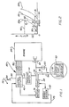
- Fig. 1 is a schematic illustration of a pump control apparatus constructed in accordance with the present invention, the apparatus being illustrated in association with the engine of a vehicle;
- Fig. 2 is a chart illustrating a series of pump output characteristic curves which indicate the manner in which pump output varies with pump operating speed for different pump operating conditions;
- Fig. 3 is a sectional view of a pressure switch used in the control apparatus of Fig. 1 to determine when the pump has a predetermined output pressure;
- Fig. 4 is a sectional view illustrating the construction of a valve which is adjusted to limit the maximum rate at which fuel is conducted to an engine;
- Fig. 5 is a schematic illustration of an analog embodiment of the control apparatus;
- Fig. 6 is a schematic illustration of circuitry utilized in the control apparatus of Fig. 5;
- Fig. 7 is a schematic illustration of a digital embodiment of the control apparatus;
- Fig. 8 is a schematic illustration of an embodiment of the control apparatus which utilizes a microprocessor; and
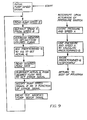
- Fig. 9 is an illustration of a flow chart for the control apparatus of Fig. 8.
- A control apparatus 20 (Fig. 1) constructed and operated in accordance with the present invention is utilized to control the operation of a
pump 22 of a pump and motor assembly to provide a desired rate of flow of fuel to a vehicle engine 24. During operation of the engine 24, changes will occur in the fuel pump operating conditions, that is, changes will occur in ambient temperature and pressure, leakage between working chambers of the pump, and friction and viscous drag on pump components. In addition, the components of thepump 22 will wear as the pump is used to further vary the pump operating conditions. - A change in fuel pump operating conditions results in a shift of a fuel pump output characteristic curve which indicates the manner in whic fuel pump output varies with pump operating speed. When the
fuel pump 22 is being operated under standard or ideal operating conditions, the pumpoutput characteristic curve 28 is disposed in the position shown in solid lines in Fig. 2. However as pump operating conditions change, the pump output characteristic curve will shift toward either the curve illustrated in dashed lines at 28a in Fig. 2 or toward the curve illustrated in dashed lines at 28b in Fig. 2. - The
curves pump 22 varies with pump operating speed for different pump operating conditions. Thecurves pump 22. Although theoperating characteristic curves pump 22 were determined by testing other pumps having the same construction as thepump 22, the curves accurately reflect the manner in which the output of thepump 22 varies with pump speed and operating conditions. - The shift in the pump
output characteristic curve 28 due to changes in pump operating conditions results in a change in the speed at which thepump 22 must be driven in order to obtain a desired fuel flow rate. Thus, if it is desired to obtain the fuel flow rate indicated by the dashed line 30 in Fig. 2, it would be necessary to drive thepump 22 at the speed indicated by thedashed line 32 when the pump is being operated under the standard or ideal conditions represented by the pumpoutput characteristic curve 28. However, if a change in pump operating conditions causes the efficiency of the pump to increase, there is a shift in the pump characteristic curve toward the left (as viewed in Fig. 2) to the position indicated at 28a. It is then necessary to drive the pump at a somewhat lower speed indicated by thedashed line 34 to obtain a fluid flow rate indicated by the line 30. - Similarly, if a change in pump operating conditions causes the efficiency of the
pump 22 to decrease, there is a shift in the pump characteristic curve toward the right (as viewed in Fig. 2) to the position indicated at 28b. It is then necessary to drive the pump at a somewhat higher speed indicated by thedashed line 36 to obtain a flow rate indicated by the line 30. - In the control system illustrated in Fig. 1, the rate of flow of fuel to the vehicle engine 24 is controlled by varying the speed at which the
pump 22 is driven. Thus, to increase the rate of flow of fuel to the engine 24 to a desired fuel flow rate, the output speed of thepump 22 is increased to a speed corresponding to the desired fuel flow rate. When the rate of flow of fuel to the engine 24 is to be decreased to a different fuel flow rate, the speed at which the pump is driven is decreased to a speed corresponding to the reduced fuel flow rate. The desired fuel flow rate varies as a function of throttle position, air-fuel ratio, and engine load. - Changes in the pump operating conditions and the resulting shifts in the pump output characteristic curve affect the rate at which fuel is discharged from the
pump 22 for a given pump operating speed. Therefore, it is necessary to control the operating speed of thepump 22 as a function of both variations in the pump operating conditions and as a function of variations in the desired fuel flow rate to the engine. Variations in the desired fuel flow rate include variations in throttle demand and engine fuel system requirements. If the pump operating speed was controlled merely as a function of a desired fuel flow rate to the engine, the actual fuel flow rate to the engine would be different than the desired fuel flow rate due to shifting of the pump output characteristic curve with changes in pump operating conditions. - In order to enable the control apparatus 20 to compensate for changes in pump operating conditions, the control apparatus senses actual fuel pump operating characteristics and transmits signals corresponding to these operating characteristics to control
circuitry 42. Although different pump operating characteristics could be sensed in different ways, it is preferred to sense the output pressure from thepump 22 with apressure switch 44. Thepressure switch 44 is actuated when the fluid pressure in afuel line 48 extending between thepump 22 and the engine 24 reaches a predetermined pressure corresponding to the fuel flow rate indicated by the dashed line 30 in Fig. 2. - During operation of the
pump 22, fuel is supplied from atank 50 to thepump 22 by acharge pump 52 through a fuel line orconduit 54. Excess fuel supplied to thepump 22 by thecharge pump 52 is returned to thefuel tank 50 through aconduit 56. When the pump output pressure in theconduit 48 exceeds a predetermined pressure, thepressure switch 44 is actuated and a signal is transmitted to thecontrol circuitry 42 through alead 60. - The
pump 22 is discharging fuel through theline 48 to a constant size orifice in a fuel control valve 64. Hence, the pressure in theconduit 48 varies as a direct function of the rate of flow in theconduit 48. Therefore, when a predetermined pressure is obtained in thefuel line 48, a predetermined fuel flow rate is present. This predetermined fuel flow rate is the fuel flow rate represented by the dashed line 30 in Fig. 2. - In order to locate the pump characteristic curve relative to the pump speed and pump output coordinates of Fig. 2, it is necessary to know the speed at which the pump is operating when the predetermined fuel flow rate represented by the dashed line 30 is present. Accordingly, a speed sensor or
tachometer 68 is connected with thepump 22 and provides an output signal over a lead 70 to thecontrol circuitry 42. The output signal from thespeed sensor 68 is indicative of the speed at which the pump is actually being driven. - The
control circuitry 42 utilizes two operating characteristics, that is speed and output pressure, of thepump 22 to determine the location of a point on one curve of the series or family of pump output characteristic curves represented in Fig. 2 by thecurves motor 74 drives thepump 22. In the present instance, the characteristics of pump output pressure and pump speed are simultaneously sensed by thepressure switch 44 and speed sensor ortachometer 68. These two characteristics enable a point on one of the pump output characteristic curves of the series or family of curves to be determined in terms of pressure and speed. - Accordingly, if an operator of the vehicle actuates an accelerator pedal 78 to provide a signal over
lead 80 to controlcircuitry 42 indicating that a change in the fuel flow rate to the engine 24 is desired, thecontrol circuitry 42 merely commands themotor 74 to drive thepump 22 at a speed corresponding to the new flow rate. It should be noted that thecontrol circuitry 42 receives numerous inputs from the internal combustion engine 24 through leads indicated at 86 in Fig. 1. These inputs are combined with the desired fuel flow rate signal transmitted from an accelerator pedal actuatedsignal generator 84 to provide a desired fuel flow control signal which will maximize the performance of the engine 24 while minimizing the pollutants discharged from the engine. - When the engine 24 is initially started, the engine is operated at a relatively low idle speed and the
motor 74 drives thepump 22 to provide a predetermined relatively low fuel flow rate to the engine 24. At this time the pressure in thefuel line 48 is insufficient to actuate thepressure switch 44. - When the accelerator pedal 78 is depressed slightly to indicate a desired fuel flow rate which exceeds the fuel flow rate when the engine is idling, the
control circuitry 42 effects operation of themotor 74 to drive thepump 22 at a speed sufficient to increase the pump discharge pressure to a pressure which is effective to actuate theswitch 44. Assuming that the pump is, at this time, being operated under conditions in which the pump output characteristic curve is correctly indicated by thecurve 28a in Fig. 2, the output signal from thespeed sensor 68 at the instant thepressure switch 44 is actuated would correspond to the speed indicated in dashed lines at 34 in Fig. 2. At this time, the fuel flow rate or output pressure from thepump 22 would be represented by the dashed line 30 in Fig. 2. This information enables thecontrol circuitry 42 to properly offset the nominal pump characteristic curve represented by thesolid line 28 in Fig. 2 to command themotor 74 to drive thepump 22 at a speed corresponding to a desired fuel flow rate. - After the location of the pump output characteristic curve has been determined by the signals from the
pressure sensing switch 44 andspeed sensor 68, thecontrol circuitry 42 can accommodate changes in demand for fuel by merely adjusting the speed at which themotor 74 is operated to drive thepump 22. Thus when the accelerator pedal 78 is actuated after it has been determined that thecurve 28a represents the correct pump output characteristic curve, the speed of themotor 74 is increased to a speed corresponding to the desired fuel flow. Assuming that the throttle demand and engine requirement through thecontrol circuitry 42 have established a desired fuel flow rate indicated by the horizontal dashed line 90 in Fig. 2, thecontrol circuitry 42 would increase the voltage transmitted to themotor 74 to a voltage corresponding to the speed indicated by the position of the vertical dashedline 92 in Fig. 2. - It is contemplated that during operation of the engine 24 the conditions under which the
pump 22 is operated will change. Therefore, the actual output characteristics of thepump 22 are periodically sensed in order to detect shifts in the pump output characteristic curve. In the embodiment of the invention illustrated in Fig. 1, the pump output pressure and operating speed are simultaneously sensed each time the pump output is reduced to a predetermined value. Thus, thepressure switch 44 is effective to detect when the predetermined fuel flow rate is present each time the fuel flow rate from thepump 22 decreases to a flow rate which is less than the predetermined flow rate detected by the pressure switch. The predetermined flow rate and pressure are slightly greater than the flow rate and pressure which are present during engine idle conditions. - If during operation of the engine 24 the accelerator pedal 78 is released, the fuel flow rate to the
engine 48 is decreased to the idle fuel flow rate. Thepressure switch 44 is again actuated when the accelerator pedal is depressed and the fuel line pressure increases. This enables thecontrol circuitry 42 to determine whether or not the relatively low predetermined fuel flow rate represented by the horizontal dashed line 30 was obtained at the same speed as before or at a different speed. A change in the speed at which the predetermined flow rate is obtained clearly indicates a shift in the pump output characteristic curve as a result of a change in pump operating conditions. - Although only a
single pressure switch 44 has been shown in Fig. 1, it is contemplated that a plurality of pressure switches could be associated with thecontrol circuitry 42. Thus, a second pressure switch could be utilized to detect when the fuel flow rate to the engine falls below a predetermined fuel flow rate which is greater than the relatively low predetermined fuel flow rate detected by thepressure switch 44. This would result in a sensing of the fuel pump operating characteristics at two different pump speeds. - Although the
pressure switch 44 could have many different constructions, it is contemplated that thepressure switch 44 could advantageously be constructed in the manner shown in Fig. 3 in which the pressure switch is illustrated in an open condition. Thepressure switch 44 includes ahousing 94 having apressure chamber 96 which is connected with thefuel flow line 48 through an inlet 100. Thepressure switch 44 has a fixed contact formed by ascrew 102 which extends into thepressure chamber 96. Amovable contact 104 is formed by a plate which is secured to arubber diaphragm 106 in such a manner as to prevent leakage of fuel from thechamber 96 through acentral opening 110 in thediaphragm 106. Ametal spring 112 extends between theswitch plate 104 and anoutput terminal 114 to urge theplate 104 toward the fixedcontact 102. - When the pressure in the
fuel line 48 is below the predetermined pressure corresponding to the fuel flow rate indicated by the dashed line 30 in Fig. 2, thespring 112 is effective to cause themetal plate 104 to engage the fixedcontact 102 to complete a circuit through thepressure switch 44. When the pressure in thefuel line 48 increases to the predetermined pressure corresponding to the predetermined flow rate represented by the dashed line 30 in Fig. 2, the fluid pressure against theplate 104 anddiaphragm 106 is sufficient to move the plate out of engagement with the fixedcontact 102. The movement of theplate 104 interrupts the circuit and provides a signal to thecontrol circuitry 42 indicating that the predetermined pressure is present. At this time the predetermined fuel flow rate is present in thefuel line 48. - The
spring 112 is sized so that theplate 104 is pressed against the fixedcontact 102 until the output pressure from thepump 22 exceeds the pressure which is present at an engine idle condition by a predetermined, relatively small amount. Therefore, each time the engine operating speed is reduced to an idle speed, the full pressure in thechamber 96 decreases to a value which is insufficient to hold thepressure switch 44 open. Therefore, thepressure switch 44 is actuated each time the engine operating speed is reduced to idle speed. - It is contemplated that the
pump 22 will have a maximum fuel flow output capability which may be slightly greater than the desired maximum fuel flow to the engine 24. In order to compensate for this excess pump capacity, a trim valve 120 (Fig. 1) is provided to control the maximum pump output flow and to provide uniform flow performance with different pumps. The trim valve 120 (see Fig. 4) includes ahousing 124 which is connected in fluid communication with thefuel line 48 through aninlet 126. Avalve body 128 is disposed in avalve chamber 130 in thehousing 124. - The rate of flow of fuel through a
port 134 in thevalve body 128 is controlled by aneedle valve 136. Theneedle valve 136 has a threaded body section 140 which engages corresponding threads in thevalve body 128 to enable the position of theneedle valve 136 to be adjusted. The fuel which flows through theport 134 is conducted to anoutlet port 144 leading to apassage 146 which is connected with the drain orfluid return conduit 56. - It is contemplated that the
control circuitry 42 could be constructed many different ways. In the embodiment shown in Fig. 5, thecontrol circuitry 42 includes a function orcurve generator 150 which responds to inputs over thelines characteristic curve 28. The input to thefunction generator 150 from thespeed sensor 68 over thelead 152 indicates the actual speed at which the fuel pump is being driven by themotor 74. - The input to the function or
curve generator 150 over thelead 154 indicates the amount by which the output from the function generator is to be offset to compensate for variations in pump operating conditions. The input to thefunction generator 150 over thelead 154 comes from a sample and holdcircuit 158 which receives an input from thespeed sensor 68. When thepressure switch 44 is actuated to indicate that a predetermined fluid pressure and flow rate are present at the discharge from thepump 22, the sample and holdcircuit 158 retains the output signal from thespeed sensor 68. Until thepressure switch 44 is again actuated, the sample and holdcircuit 158 provides an output signal which is a function of the speed at which the pressure switch was actuated. - The output signal from the function or
curve generator 150 represents the actual fuel flow rate to the engine 24. The actual fuel flow rate signal from thefunction generator 150 is transmitted to afeedback amplifier 162. Thefeedback amplifier 1 62 is effective to compare the fuel flow rate indicated by the signal from thefunction generator 150 with a desired fuel flow rate signal. - The desired fuel flow rate signal is determined by the position of the accelerator pedal 78 and engine
control logic circuitry 164. The enginecontrol logic circuitry 164 receives inputs indicative of many different engine operating conditions from a plurality of sensors. These signals are combined with the throttle position input signal to provide an output signal indicative of a desired fuel flow rate. - If the desired fuel flow rate signal from the
control circuitry 164 agrees with the signal from thefunction generator 150, the output from thefeedback amplifier 162 does not vary and thepump motor 74 continues to drive the pump at the same speed. However, if there is a difference between the desired fuel flow rate signal as indicated by the enginecontrol logic circuitry 164 and the actual fuel flow rate indicated by the output from thefunction generator 150, the output from thefeedback amplifier 162 causes a corresponding change in the speed of thepump drive motor 74. Although it is preferred to utilize the enginecontrol logic circuitry 164 to determine the desired fuel flow rate as a function of many different engine operating conditions, it is contemplated that the engine control logic circuitry could be eliminated and the desired fuel flow rate determined as a function of only throttle position if desired. - In an embodiment of the invention in which the pump output characteristic curve has a linear configuration rather than the nonlinear configuration illustrated in Fig. 2, the
function generator 150 can be constructed in the manner illustrated in Fig. 6. In this embodiment of the invention the input to an inverting terminal 166 of anoperational amplifier 168 is from thespeed sensor 68 over thelead 152. This input is conducted through the resistance R2. The noninverting terminal of theoperational amplifier 168 is connected to ground. - The signal from the sample and hold circuit 158 (Fig. 5) is conducted through the lead 154 (Fig. 6) to the input of the
operational amplifier 168 through resistance R1. In this embodiment theoperational amplifier 168 is a summing amplifier. The resulting output signal over lead 172 is a voltage that represents the magnitude of fuel flow through the conduit 48:
conduit 48 is equal to the value of a resistance R, divided by the value of the resistance R, times the input voltage over the lead 154 (Wo) plus the value of the resistance R, divided by the resistance Rz times the voltage on the lead 152 (W,). The negative before the Q term results from the amplifier's inverting characteristic. - In the embodiment of the invention illustrated in Figs. 5 and 6, the
control circuitry 42 has an analog construction. In the embodiment illustrated in Fig. 7, the control circuitry 42a has a digital construction. It is contemplated that the embodiment 42a of the control circuitry illustrated in Fig. 7 may be preferred to theembodiment 42 shown in Figs. 5 and 6. - The control circuitry 42a includes a
curve memory unit 180 in which groups of data corresponding to the pump output characteristic curves for different pump operating conditions are stored. Thus, each group of data stored in thecurve memory 180 corresponds to a pump output characteristic curve for a particular operating condition. For example, one group of data would represent the pump outputcharacteristic curve 28 of Fig. 2, another group of data would represent the pump outputcharacteristic curve 28a of Fig. 2, and the third group of data would represent the curve 28b of Fig. 2. - Each group of data has an address which is composed of two parts. The first part of the address is representative of the pump operating conditions and indicates which group of data is applicable. The second part of the address is representative of the speed at which the pump is being driven to enable the flow rate to be determined from the correct group of data.
- The part of the address which indicates pump operating conditions is provided by a
digital signal latch 184. Thedigital signal latch 184 is provided with an input from thespeed sensor 68 through an analog todigital convertor 186. When thepressure switch 44 is actuated, thedigital signal latch 184 stores the speed at which the pump is being driven to obtain the known fuel flow pressure and rate. - The output from the
digital signal latch 184 is a function of the speed signal at which the predetermined fuel flow rate was obtained. The output signal from the digital signal latch forms the first part of an address in thememory unit 180 and is indicative of the particular group of data which is to be read. - As the fuel flow rate is varied, the output from the
speed sensor 68 is varied. This signal is transmitted to thememory unit 180. This enables the actual pump operating speed to be used in association with the group of data selected on the output from thedigital signal latch 184. The data read out from the selected group of data in thememory unit 180 is transmitted to afeedback amplifier 188. - The group of data selected by the output from the
digital signal latch 184 corresponds to the pump operating characteristic curve which is representative of actual pump operating conditions at the time when thepressure switch 44 was last actuated. This group of data is utilized at least until theswitch 44 is again actuated and the pump operating conditions are again sensed. If the pump operating conditions do not change by the next time thepressure switch 44 is actuated, the output from thedigital signal latch 184 will not change and the same group of data will continue to be read. However, if the pump operating conditions have changed, the output from thedigital signal latch 184 will change to indicate a new group of data the next time thepressure switch 44 is actuated. - The
feedback amplifier 188 compares the output from thememory unit 180 with the desired fuel flow rate as indicated by the setting of the accelerator pedal 78 (Fig. 7) and the requirements of the enginecontrol logic circuitry 164. If the actual fuel flow rate as indicated by thememory unit 180 is equal to the desired fuel flow rate as indicated by the setting of the accelerator pedal 78 and requirements of thelogic circuitry 164, the operating speed of thepump motor 74 remains constant. However, if there is a difference between the fuel flow rate indicated by thememory unit 180 and the desired fuel flow rate, the output from thefeedback amplifier 188 is effective to change the speed at which themotor 74 drives thepump 22. - It is also contemplated that the
control circuitry 42 could include a microprocessor which would be utilized in association with a suitable memory unit. This embodiment of the invention is illustrated in Fig. 8 and includes a microprocessor 194 which is effective to transmit and receive data from adata bus 196. In addition, the microprocessor is effective to transmit data to anaddress bus 198. The data and address buses are connected with amemory unit 200. A flow chart for the operation of the microprocessor 194 andmemory unit 200 is set forth in Fig. 9. - When the engine 24 is started, the inputs from the engine control and throttle position sensors are processed through the microprocessor 194 (Fig. 8) and
memory unit 200. An initial pump speed signal is transmitted through anoutput buffer 202 to thepump motor 74 through a digital toanalog convertor 204. Assuming that thepressure switch 44 is then actuated, a program interrupt signal is provided. - The program interrupt signal causes the memory 200 (Fig. 8) to store an operating condition speed signal (A) which corresponds to the actual speed of the
motor 74 when the predetermined flow rate required to actuate thepressure switch 44 is present. The pump speed and pressure level designate the specific pump output characteristic curve that applies as well as the value of the predetermined flow rate in thememory unit 200. The speed increment that establishes the predetermined flow rate magnitude is graphically shown as the intersection of horizontal line 30 withvertical line 34 which is designated point A oncurve 28a of Fig. 2. - During continued vehicle operation, the actual pump flow rate for a particular engine operating speed is represented by the dashed line 90. The line 90 intersects the
curve 28a at a point designated as point B in Fig. 2. Point B is above the speed at which the pressure switch is actuated. The microprocessor establishes the magnitude of the speed difference between the speed represented as line 30, that is attained at the predetermined flow and the pump's actual speed depicted as a line 90, Fig. 2. This speed difference, the horizontal distance between point B and point A, Fig. 2, is translatable, through thememory 200, to a value of flow graphically shown asvertical line 92, Fig. 2. The microprocessor adds the predetermined flow vector shown asline 32 to the flow vector represented asline 92, in Fig. 2, to obtain the actual pump flow rate. - The desired fuel flow rate, as indicated by the position of the accelerator pedal and the engine logic control requirement signals, is then read and subtracted from the actual pump flow rate signal to provide an error signal. A new pump speed signal is then produced as a function of the error signal. The new pump speed signal is effective to cause the speed of operation of the
motor 74 to be changed in order to provide a fuel flow rate corresponding to the desired fuel flow rate. The foregoing steps are repeated continuously during operation of the engine 24 andcontrol circuitry 42. It should be noted that the main program indicated on the left portion of Fig. 9 is interrupted whenever thepressure switch 44 senses that the predetermined fuel flow rate is present. - In the embodiments of the invention previously described, the pump operating characteristics of output pressure and speed were simultaneously sensed by the
pressure switch 44 and thespeed sensor 68. However, thepump 22 andmotor 74 operate as an assembly and preferably have the same construction shown in US-A-4,207,033. Due to the interaction between thepump 22 andmotor 74, it is contemplated that operating characteristics of either the pump or the motor could be sensed. For example, the operating speed of themotor 74 or the back electromotive force of the motor could be sensed rather than pump operating speed. Rather than sensing the pump operating characteristic of output pressure, the torque required to drive themotor 74 or the motor field current could be sensed. - In addition, it is contemplated that the present invention may be utilized in environments other than in association with an engine. In the illustrated embodiments of the invention, the pump operating characteristic curve was determined each time the pump output pressure was decreased below a predetermined pressure. However, it is contemplated that the pump operating characteristic curve could be determined in response to the occurrence of other events.
- In view of the foregoing it is apparent that the present invention provides a system which is effective to vary the speed at which a
motor 74 drives thefuel pump 22 to compensate for changes in fuel pump operating characteristics with changes in pump operating conditions. In order to utilize the system, it is necessary to determined how fuel pump output will vary with changes in pump operating speed under many different operating conditions. This is determined by testing a substantial number of pumps having the same construction as thepump 22 under many different operating conditions. These tests make it possible to statistically predict how the output of thepump 22 will vary with variations in operating conditions, as represented by a series of pump output characteristic curves typified by thecurves - Once this has been done, it is merely necessary to determine which pump output characteristic curve of the series of curves indicates how pump output will vary with pump speed under the operating conditions which are present at any given time. Although this can be done in many different ways, it is advantageously done by using a
pressure switch 44 to detect when fuel is discharged at a predetermined pressure. By simultaneously sensing pump operating speed with thesensor 68 and pump output pressure with thepressure switch 44, it is possible to determine a point on a pump output characteristic curve of a series or family of curves typified by thecurves - It is contemplated that the fuel pump operating conditions will vary during operation of the associated engine. Therefore, the pump operating characteristics are periodically sensed during operation of the engine in order to detect changes in the pump operating conditions. Although the sensing of the pump operating characteristics could be done in response to many different events, such as the passage of a predetermined amount of time, the pump operating characteristics are advantageously sensed each time the
pressure switch 44 is actuated. - Although the actual
pump control circuitry 42 could take many different forms, it is contemplated that afunction generator 150 could be utilized to generate a curve having a configuration corresponding to the pump output characteristic curve. The output from thefunction generator 150 is modified as a function of changes in pump operating conditions as reflected by the sensing of actual pump operating characteristics. - In a digital embodiment of the control apparatus (Fig. 7), a plurality of groups of data are stored in a
memory 180. Each group of data corresponds to a particular pump output operating condition. Thememoty 180 is searched to locate the data at an address corresponding to a particular pump operating speed and operating condition. In addition, it is contemplated that in still another embodiment a microprocessor 194 (Fig. 8) could be utilized in association with amemory 200 which stores data corresponding to the configuration of a pump output characteristic curve. This data is then modified in accordance with the sensed pump operating conditions.
Claims (10)
Applications Claiming Priority (2)
| Application Number | Priority Date | Filing Date | Title |
|---|---|---|---|
| US06/068,943 US4248194A (en) | 1979-08-23 | 1979-08-23 | Method and apparatus for controlling the operation of a pump |
| US68943 | 1979-08-23 |
Publications (2)
| Publication Number | Publication Date |
|---|---|
| EP0024645A1 EP0024645A1 (en) | 1981-03-11 |
| EP0024645B1 true EP0024645B1 (en) | 1984-01-25 |
Family
ID=22085710
Family Applications (1)
| Application Number | Title | Priority Date | Filing Date |
|---|---|---|---|
| EP80104821A Expired EP0024645B1 (en) | 1979-08-23 | 1980-08-14 | Method and apparatus for controlling the operation of a pump |
Country Status (7)
| Country | Link |
|---|---|
| US (1) | US4248194A (en) |
| EP (1) | EP0024645B1 (en) |
| JP (1) | JPS5669427A (en) |
| CA (1) | CA1143038A (en) |
| DE (1) | DE3066284D1 (en) |
| DK (1) | DK362280A (en) |
| IE (1) | IE49863B1 (en) |
Families Citing this family (61)
| Publication number | Priority date | Publication date | Assignee | Title |
|---|---|---|---|---|
| US4526513A (en) * | 1980-07-18 | 1985-07-02 | Acco Industries Inc. | Method and apparatus for control of pipeline compressors |
| US4370098A (en) * | 1980-10-20 | 1983-01-25 | Esco Manufacturing Company | Method and apparatus for monitoring and controlling on line dynamic operating conditions |
| US4422420A (en) * | 1981-09-24 | 1983-12-27 | Trw Inc. | Method and apparatus for fuel control in fuel injected internal combustion engines |
| JPS58172452A (en) * | 1982-04-02 | 1983-10-11 | Toyota Motor Corp | Electronic controlled type fuel injection device |
| US4487181A (en) * | 1982-04-03 | 1984-12-11 | Lucas Industries Public Limited Company | Fuel supply system for an internal combustion engine |
| US4515529A (en) * | 1982-10-21 | 1985-05-07 | Woodhull William M | Energy transducer for hydraulic wind power conversion system and instrumentation therefor |
| US4705457A (en) * | 1984-01-18 | 1987-11-10 | Belvin Properties Limited | Monitoring of fluid flow |
| US4534707A (en) * | 1984-05-14 | 1985-08-13 | Caterpillar Tractor Co. | Hydrostatic vehicle control |
| US4523892A (en) * | 1984-05-14 | 1985-06-18 | Caterpillar Tractor Co. | Hydrostatic vehicle control |
| GB8521244D0 (en) * | 1985-08-24 | 1985-10-02 | Gas Power International Ltd | Dual fuel compression ignition engine |
| DE3616455A1 (en) * | 1986-05-15 | 1987-11-19 | Bosch Gmbh Robert | CONTROL UNIT FOR COMBUSTION ENGINES |
| US4707646A (en) * | 1986-05-29 | 1987-11-17 | Carrier Corporation | Method of limiting motor power output |
| JPH0681931B2 (en) * | 1986-06-25 | 1994-10-19 | 日本電装株式会社 | Fuel pump controller |
| US4920942A (en) * | 1987-04-24 | 1990-05-01 | Diesel Kiki Co., Ltd. | Method and apparatus for supplying fuel to internal combustion engines |
| US4756291A (en) * | 1987-04-27 | 1988-07-12 | Ford Motor Company | Pressure control for the fuel system of an internal combustion engine |
| US4790277A (en) * | 1987-06-03 | 1988-12-13 | Ford Motor Company | Self-adjusting fuel injection system |
| US4905785A (en) * | 1987-12-24 | 1990-03-06 | Paccar Inc | Intermediate governor system |
| US5182951A (en) * | 1988-01-27 | 1993-02-02 | Jorritsma Johannes N | Method and aparatus for calculating flow rates through a pumping station |
| JPH01302386A (en) * | 1988-05-31 | 1989-12-06 | Matsushita Electron Corp | Projection type image display |
| US4951636A (en) * | 1988-11-28 | 1990-08-28 | Walbro Corporation | Constant pressure-differential fuel injection system |
| US4926829A (en) * | 1988-11-28 | 1990-05-22 | Walbro Corporation | Pressure-responsive fuel delivery system |
| JP2869464B2 (en) * | 1989-05-30 | 1999-03-10 | 富士重工業株式会社 | Fuel injection control device for two-cycle engine |
| JPH0324532A (en) * | 1989-06-21 | 1991-02-01 | Seiko Epson Corp | Illuminator |
| US4971005A (en) * | 1989-07-28 | 1990-11-20 | United Technologies Corporation | Fuel control utilizing a multifunction valve |
| US5044344A (en) * | 1989-10-16 | 1991-09-03 | Walbro Corporation | Pressure-responsive fuel delivery system |
| US6394072B1 (en) * | 1990-08-31 | 2002-05-28 | Yamaha Hatsudoki Kabushiki Kaisha | Fuel injection device for engine |
| ATE163070T1 (en) * | 1991-05-15 | 1998-02-15 | Orbital Eng Pty | FUEL INJECTION SYSTEM FOR AN INTERNAL COMBUSTION ENGINE |
| US5240380A (en) * | 1991-05-21 | 1993-08-31 | Sundstrand Corporation | Variable speed control for centrifugal pumps |
| US5133323A (en) * | 1991-06-25 | 1992-07-28 | Siemens Automotive L.P. | Intake manifold pressure compensation for the closed-loop pressure regulation of a fuel pump |
| US5284119A (en) * | 1991-07-08 | 1994-02-08 | Walter Potoroka, Sr. | Internal combustion engine fuel injection apparatus and system |
| US5191867A (en) * | 1991-10-11 | 1993-03-09 | Caterpillar Inc. | Hydraulically-actuated electronically-controlled unit injector fuel system having variable control of actuating fluid pressure |
| US5265644A (en) * | 1992-06-02 | 1993-11-30 | Walbro Corporation | Fuel pressure regulator |
| GB2268225B (en) * | 1992-06-29 | 1995-07-05 | Ford Motor Co | A fuel supply arrangement |
| JP3060266B2 (en) * | 1992-11-09 | 2000-07-10 | 株式会社ユニシアジェックス | Engine fuel supply |
| US5313924A (en) * | 1993-03-08 | 1994-05-24 | Chrysler Corporation | Fuel injection system and method for a diesel or stratified charge engine |
| US5564391A (en) * | 1993-06-16 | 1996-10-15 | Caterpillar Inc. | Electronic control for a hydraulic-actuator unit injector fuel system and method for operating same |
| US5355859A (en) * | 1993-09-16 | 1994-10-18 | Siemens Automotive L.P. | Variable pressure deadheaded fuel rail fuel pump control system |
| US5525043A (en) * | 1993-12-23 | 1996-06-11 | Caterpillar Inc. | Hydraulic power control system |
| US5468126A (en) * | 1993-12-23 | 1995-11-21 | Caterpillar Inc. | Hydraulic power control system |
| US5379741A (en) * | 1993-12-27 | 1995-01-10 | Ford Motor Company | Internal combustion engine fuel system with inverse model control of fuel supply pump |
| DE4344777C2 (en) * | 1993-12-28 | 1998-06-04 | Technoflow Tube Systems Gmbh | Fuel supply system for a motor vehicle with a gasoline engine |
| US5579739A (en) * | 1994-01-14 | 1996-12-03 | Walbro Corporation | Returnless fuel system with demand fuel pressure regulator |
| US5590631A (en) * | 1994-01-14 | 1997-01-07 | Walbro Corporation | Fuel system accumulator |
| FR2730767B1 (en) * | 1995-02-21 | 1997-04-18 | Inst Francais Du Petrole | METHOD AND DEVICE FOR REGULATING A POLYPHASIC PUMPING ASSEMBLY |
| DE19548278B4 (en) * | 1995-12-22 | 2007-09-13 | Robert Bosch Gmbh | Method and device for controlling an internal combustion engine |
| US5708201A (en) * | 1996-05-24 | 1998-01-13 | Pierburg Instruments, Inc. | Fuel delivery measurement system with automatic pump matching |
| US6024072A (en) * | 1997-05-21 | 2000-02-15 | Aisan Kogyo Kabushiki Kaisha | Fuel pump control apparatus |
| US6053702A (en) * | 1998-07-15 | 2000-04-25 | Sears; Samuel D. | Portable water pump having a pressure control circuit with a bypass conduit |
| DE19831997A1 (en) * | 1998-07-16 | 2000-01-20 | Ewald Hennel | Process for regulating the pressure of a fluid |
| US6877488B2 (en) * | 2002-05-29 | 2005-04-12 | Nartron Corporation | Vehicle fuel management system |
| US7607437B2 (en) * | 2003-08-04 | 2009-10-27 | Cardinal Health 203, Inc. | Compressor control system and method for a portable ventilator |
| BRPI0413275A (en) * | 2003-08-04 | 2006-10-10 | Pulmonetic Systems Inc | portable fan and portable fan system |
| US8156937B2 (en) * | 2003-08-04 | 2012-04-17 | Carefusion 203, Inc. | Portable ventilator system |
| US8118024B2 (en) * | 2003-08-04 | 2012-02-21 | Carefusion 203, Inc. | Mechanical ventilation system utilizing bias valve |
| WO2006004080A1 (en) * | 2004-07-05 | 2006-01-12 | Komatsu Ltd. | Rotation control device, rotation control method, and construction machine |
| US7762080B2 (en) * | 2006-11-16 | 2010-07-27 | Honeywell International Inc. | Fuel metering pump calibration method |
| US7431020B2 (en) * | 2006-11-30 | 2008-10-07 | Denso International America, Inc. | Adaptive fuel delivery module in a mechanical returnless fuel system |
| US8801393B2 (en) * | 2007-10-12 | 2014-08-12 | Pierce Manufacturing Inc. | Pressure control system and method |
| DE102012016591B4 (en) * | 2012-08-16 | 2016-01-14 | Getrag Getriebe- Und Zahnradfabrik Hermann Hagenmeyer Gmbh & Cie Kg | Temperature determination method in a hydraulic system |
| US20150204322A1 (en) * | 2014-01-17 | 2015-07-23 | Caterpillar Inc. | Pump system having speed-based control |
| WO2019172372A1 (en) * | 2018-03-08 | 2019-09-12 | 株式会社Ihi | Fuel supply control device |
Family Cites Families (22)
| Publication number | Priority date | Publication date | Assignee | Title |
|---|---|---|---|---|
| US2687123A (en) * | 1950-12-05 | 1954-08-24 | Fuelcharger Corp | Fuel injection system |
| FR1228832A (en) * | 1958-11-18 | 1960-09-02 | R E T E M Rech S Et Etudes Ele | Low pressure fuel injection device |
| FR1391104A (en) * | 1964-01-22 | 1965-03-05 | Servomechanism device for simultaneous incorporation of one or more secondary products into a main product | |
| DE2157331A1 (en) * | 1970-11-18 | 1972-06-22 | Upjohn Co | Method and device for establishing and maintaining a predetermined throughput rate |
| GB1429307A (en) * | 1972-04-04 | 1976-03-24 | Cav Ltd | Control systems for engines |
| US3973538A (en) * | 1973-01-06 | 1976-08-10 | C.A.V. Limited | Fuel systems for engines |
| GB1474517A (en) * | 1973-05-03 | 1977-05-25 | ||
| DD106216A1 (en) * | 1973-07-20 | 1974-06-05 | ||
| US3935851A (en) * | 1973-12-26 | 1976-02-03 | Chrysler Corporation | Fuel metering system for spark ignition engines |
| US4125093A (en) * | 1974-09-30 | 1978-11-14 | Chrysler Corporation | Solid state fluid flow sensor |
| DE2454907A1 (en) * | 1974-11-20 | 1976-08-12 | Bosch Gmbh Robert | CONTROL DEVICE FOR A FUEL INJECTION SYSTEM IN COMBUSTION MACHINES WITH EXTERNAL IGNITION |
| PL101186B1 (en) * | 1976-02-17 | 1978-12-30 | AUTOMATIC ADJUSTMENT OF DOSAGE OF LIQUID FUELS, ESPECIALLY FOR INDUSTRIAL STOVES | |
| GB1596503A (en) * | 1976-11-04 | 1981-08-26 | Lucas Industries Ltd | Electronic fuel injection control for an internal combustion engine |
| GB1596501A (en) * | 1976-11-04 | 1981-08-26 | Lucas Industries Ltd | Electronic fuel injection control for an internal combustion engine |
| US4207033A (en) * | 1976-12-06 | 1980-06-10 | Trw Inc. | Pump and motor assembly for use in regulating a flow of fuel from a source of fuel to an operating chamber of an engine of a vehicle |
| US4108574A (en) * | 1977-01-21 | 1978-08-22 | International Paper Company | Apparatus and method for the indirect measurement and control of the flow rate of a liquid in a piping system |
| JPS5459510A (en) * | 1977-10-19 | 1979-05-14 | Hitachi Ltd | Electronic type engine controller |
| DE2805876A1 (en) * | 1978-02-11 | 1979-08-16 | Bosch Gmbh Robert | ELECTRICAL MONITORING DEVICE FOR FALSE RESISTANT SENSORS AND CONSUMERS, IN PARTICULAR IN THE AREA OF FUEL MEASUREMENT IN COMBUSTION MACHINES |
| DE2807924A1 (en) * | 1978-02-24 | 1979-09-06 | Bosch Gmbh Robert | PROCEDURE AND DEVICE FOR CORRECTING THE AMOUNT OF FUEL ADJUSTED TO A COMBUSTION ENGINE |
| DE2808731A1 (en) * | 1978-03-01 | 1979-09-06 | Bosch Gmbh Robert | PROCEDURE FOR OPERATING A FUEL INJECTION SYSTEM AND FUEL INJECTION SYSTEM |
| DE2812442A1 (en) * | 1978-03-22 | 1979-10-04 | Bosch Gmbh Robert | PROCESS AND DEVICE FOR DETERMINING SETTING SIZES IN COMBUSTION MACHINES |
| DE2824190A1 (en) * | 1978-06-02 | 1979-12-06 | Bosch Gmbh Robert | MICRO COMPUTER SYSTEM FOR THE CONTROL OF OPERATING PROCEDURES IN MOTOR VEHICLES, WITH A DIAGNOSTIC DEVICE FOR CHECKING THE VEHICLE |
-
1979
- 1979-08-23 US US06/068,943 patent/US4248194A/en not_active Expired - Lifetime
-
1980
- 1980-08-07 IE IE1648/80A patent/IE49863B1/en unknown
- 1980-08-14 DE DE8080104821T patent/DE3066284D1/en not_active Expired
- 1980-08-14 EP EP80104821A patent/EP0024645B1/en not_active Expired
- 1980-08-22 JP JP11486080A patent/JPS5669427A/en active Granted
- 1980-08-22 CA CA000358829A patent/CA1143038A/en not_active Expired
- 1980-08-22 DK DK362280A patent/DK362280A/en not_active Application Discontinuation
Also Published As
| Publication number | Publication date |
|---|---|
| DE3066284D1 (en) | 1984-03-01 |
| EP0024645A1 (en) | 1981-03-11 |
| CA1143038A (en) | 1983-03-15 |
| US4248194A (en) | 1981-02-03 |
| JPS6354126B2 (en) | 1988-10-26 |
| JPS5669427A (en) | 1981-06-10 |
| IE801648L (en) | 1981-02-23 |
| IE49863B1 (en) | 1985-12-25 |
| DK362280A (en) | 1981-02-24 |
Similar Documents
| Publication | Publication Date | Title |
|---|---|---|
| EP0024645B1 (en) | Method and apparatus for controlling the operation of a pump | |
| USRE32030E (en) | Closed loop controlled auxiliary air delivery system for internal combustion engine | |
| US4622936A (en) | Electronic fuel controller for an automotive internal combustion engine | |
| US5019799A (en) | Electronic device with self-monitor for an automotive vehicle | |
| US4155332A (en) | Electronic fuel injection system in an internal combustion engine | |
| US4506639A (en) | Method and system for controlling the idle speed of an internal combustion engine at variable ignition timing | |
| US4244023A (en) | Microprocessor-based engine control system with acceleration enrichment control | |
| US4601199A (en) | Method and device for self-diagnosis of final setting members | |
| CA1193341A (en) | Electronic engine control system | |
| US5630383A (en) | Lubricating oil supplying system for engine | |
| US5855533A (en) | Automotive powertrain control | |
| EP0142101A2 (en) | Automotive engine control system capable of detecting specific engine operating conditions and projecting subsequent engine operating patterns | |
| KR0141370B1 (en) | Automatic control process and device, in particular lambda control | |
| US4637361A (en) | Non-adjustable throttle position indicator | |
| EP0640769A1 (en) | Automatic warming-up apparatus and method thereof in hydraulic systems | |
| US4531490A (en) | Idling speed feedback control method having fail-safe function for abnormalities in functioning of crank angle position-detecting system of an internal combustion engine | |
| GB2125577A (en) | Self monitoring system | |
| EP0177318B1 (en) | Idling speed feedback control method for internal combustion engines | |
| US4387682A (en) | Method and apparatus for controlling the air intake of an internal combustion engine | |
| US4995366A (en) | Method for controlling air-fuel ratio for use in internal combustion engine and apparatus for controlling the same | |
| EP0378814B1 (en) | Method of controlling air-fuel ratio | |
| EP0398903B1 (en) | Method for acceleration enrichment in fuel injection systems | |
| EP0280878B1 (en) | Engine rotation speed detecting apparatus | |
| KR890004296B1 (en) | Fuel injection timing control method for diesel engine | |
| EP0245117B1 (en) | Fuel control apparatus for a fuel injection system of an internal combustion engine |
Legal Events
| Date | Code | Title | Description |
|---|---|---|---|
| PUAI | Public reference made under article 153(3) epc to a published international application that has entered the european phase |
Free format text: ORIGINAL CODE: 0009012 |
|
| AK | Designated contracting states |
Designated state(s): DE FR GB IT LU NL |
|
| 17P | Request for examination filed |
Effective date: 19810909 |
|
| ITF | It: translation for a ep patent filed |
Owner name: STUDIO TORTA SOCIETA' SEMPLICE |
|
| GRAA | (expected) grant |
Free format text: ORIGINAL CODE: 0009210 |
|
| AK | Designated contracting states |
Designated state(s): DE FR GB IT LU NL |
|
| REF | Corresponds to: |
Ref document number: 3066284 Country of ref document: DE Date of ref document: 19840301 |
|
| ET | Fr: translation filed | ||
| PGFP | Annual fee paid to national office [announced via postgrant information from national office to epo] |
Ref country code: FR Payment date: 19840827 Year of fee payment: 5 |
|
| PG25 | Lapsed in a contracting state [announced via postgrant information from national office to epo] |
Ref country code: LU Free format text: LAPSE BECAUSE OF NON-PAYMENT OF DUE FEES Effective date: 19840831 |
|
| PGFP | Annual fee paid to national office [announced via postgrant information from national office to epo] |
Ref country code: DE Payment date: 19840917 Year of fee payment: 5 |
|
| PLBE | No opposition filed within time limit |
Free format text: ORIGINAL CODE: 0009261 |
|
| STAA | Information on the status of an ep patent application or granted ep patent |
Free format text: STATUS: NO OPPOSITION FILED WITHIN TIME LIMIT |
|
| 26N | No opposition filed | ||
| PGFP | Annual fee paid to national office [announced via postgrant information from national office to epo] |
Ref country code: NL Payment date: 19860831 Year of fee payment: 7 |
|
| PG25 | Lapsed in a contracting state [announced via postgrant information from national office to epo] |
Ref country code: NL Effective date: 19880301 |
|
| NLV4 | Nl: lapsed or anulled due to non-payment of the annual fee | ||
| PG25 | Lapsed in a contracting state [announced via postgrant information from national office to epo] |
Ref country code: FR Free format text: LAPSE BECAUSE OF NON-PAYMENT OF DUE FEES Effective date: 19880429 |
|
| PG25 | Lapsed in a contracting state [announced via postgrant information from national office to epo] |
Ref country code: DE Effective date: 19880503 |
|
| GBPC | Gb: european patent ceased through non-payment of renewal fee | ||
| REG | Reference to a national code |
Ref country code: FR Ref legal event code: ST |
|
| PG25 | Lapsed in a contracting state [announced via postgrant information from national office to epo] |
Ref country code: GB Free format text: LAPSE BECAUSE OF NON-PAYMENT OF DUE FEES Effective date: 19881118 |