KR890004296B1 - Fuel injection timing control method for diesel engine - Google Patents
Fuel injection timing control method for diesel engine Download PDFInfo
- Publication number
- KR890004296B1 KR890004296B1 KR1019860000903A KR860000903A KR890004296B1 KR 890004296 B1 KR890004296 B1 KR 890004296B1 KR 1019860000903 A KR1019860000903 A KR 1019860000903A KR 860000903 A KR860000903 A KR 860000903A KR 890004296 B1 KR890004296 B1 KR 890004296B1
- Authority
- KR
- South Korea
- Prior art keywords
- fuel injection
- injection timing
- diesel engine
- engine
- output
- Prior art date
Links
Images


Classifications
-
- F—MECHANICAL ENGINEERING; LIGHTING; HEATING; WEAPONS; BLASTING
- F02—COMBUSTION ENGINES; HOT-GAS OR COMBUSTION-PRODUCT ENGINE PLANTS
- F02D—CONTROLLING COMBUSTION ENGINES
- F02D41/00—Electrical control of supply of combustible mixture or its constituents
- F02D41/02—Circuit arrangements for generating control signals
- F02D41/14—Introducing closed-loop corrections
- F02D41/16—Introducing closed-loop corrections for idling
-
- F—MECHANICAL ENGINEERING; LIGHTING; HEATING; WEAPONS; BLASTING
- F02—COMBUSTION ENGINES; HOT-GAS OR COMBUSTION-PRODUCT ENGINE PLANTS
- F02D—CONTROLLING COMBUSTION ENGINES
- F02D35/00—Controlling engines, dependent on conditions exterior or interior to engines, not otherwise provided for
- F02D35/0015—Controlling engines, dependent on conditions exterior or interior to engines, not otherwise provided for using exhaust gas sensors
- F02D35/0046—Controlling fuel supply
- F02D35/0092—Controlling fuel supply by means of fuel injection
-
- F—MECHANICAL ENGINEERING; LIGHTING; HEATING; WEAPONS; BLASTING
- F02—COMBUSTION ENGINES; HOT-GAS OR COMBUSTION-PRODUCT ENGINE PLANTS
- F02D—CONTROLLING COMBUSTION ENGINES
- F02D41/00—Electrical control of supply of combustible mixture or its constituents
- F02D41/02—Circuit arrangements for generating control signals
- F02D41/14—Introducing closed-loop corrections
-
- F—MECHANICAL ENGINEERING; LIGHTING; HEATING; WEAPONS; BLASTING
- F02—COMBUSTION ENGINES; HOT-GAS OR COMBUSTION-PRODUCT ENGINE PLANTS
- F02D—CONTROLLING COMBUSTION ENGINES
- F02D41/00—Electrical control of supply of combustible mixture or its constituents
- F02D41/30—Controlling fuel injection
- F02D41/38—Controlling fuel injection of the high pressure type
- F02D41/40—Controlling fuel injection of the high pressure type with means for controlling injection timing or duration
- F02D41/401—Controlling injection timing
-
- F—MECHANICAL ENGINEERING; LIGHTING; HEATING; WEAPONS; BLASTING
- F02—COMBUSTION ENGINES; HOT-GAS OR COMBUSTION-PRODUCT ENGINE PLANTS
- F02B—INTERNAL-COMBUSTION PISTON ENGINES; COMBUSTION ENGINES IN GENERAL
- F02B3/00—Engines characterised by air compression and subsequent fuel addition
- F02B3/06—Engines characterised by air compression and subsequent fuel addition with compression ignition
-
- F—MECHANICAL ENGINEERING; LIGHTING; HEATING; WEAPONS; BLASTING
- F02—COMBUSTION ENGINES; HOT-GAS OR COMBUSTION-PRODUCT ENGINE PLANTS
- F02D—CONTROLLING COMBUSTION ENGINES
- F02D2250/00—Engine control related to specific problems or objectives
- F02D2250/32—Air-fuel ratio control in a diesel engine
-
- Y—GENERAL TAGGING OF NEW TECHNOLOGICAL DEVELOPMENTS; GENERAL TAGGING OF CROSS-SECTIONAL TECHNOLOGIES SPANNING OVER SEVERAL SECTIONS OF THE IPC; TECHNICAL SUBJECTS COVERED BY FORMER USPC CROSS-REFERENCE ART COLLECTIONS [XRACs] AND DIGESTS
- Y02—TECHNOLOGIES OR APPLICATIONS FOR MITIGATION OR ADAPTATION AGAINST CLIMATE CHANGE
- Y02T—CLIMATE CHANGE MITIGATION TECHNOLOGIES RELATED TO TRANSPORTATION
- Y02T10/00—Road transport of goods or passengers
- Y02T10/10—Internal combustion engine [ICE] based vehicles
- Y02T10/40—Engine management systems
Abstract
Description
제1도는 본 발명에 관한 연료 분사시기 제어방법을 적용한 디이젤기관의 연료분사시기 제어장치의 전체 구성의 일실시예를 표시하는 개략도.1 is a schematic diagram showing an embodiment of the entire configuration of a fuel injection timing control apparatus of a diesel engine to which the fuel injection timing control method according to the present invention is applied.
제2도는 본 발명의 방법을 실행하는 순서를 표시하는 플로우챠트.2 is a flowchart showing the procedure for executing the method of the present invention.
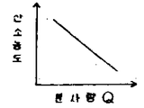
제3도는 디이젤기관의 배기가스중의 산소농도와 연료분사량(Q)과의 관계를 표시하는 그래프.3 is a graph showing the relationship between the oxygen concentration in the exhaust gas of a diesel engine and the fuel injection amount (Q).
제4도는 제1도의 산소센서출력과 산소농도와의 관계를 표시하는 그래프.4 is a graph showing the relationship between oxygen sensor output and oxygen concentration in FIG.
제5도는 산소센서출력과 연료분사량(Q)과의 관계를 표시하는 그래프.5 is a graph showing the relationship between the oxygen sensor output and the fuel injection amount (Q).
* 도면의 주요부분에 대한 부호의 설명* Explanation of symbols for main parts of the drawings
1 : 디이젤기관 2 : 엔진회전수센서1: diesel engine 2: engine speed sensor
3 : 배기관내 4 : 산소센서3: exhaust pipe 4: oxygen sensor
5 : 연료분사펌프 6 : 타이머장치5: fuel injection pump 6: timer device
7 : 입력축회전센서 8 : 출력축회전센서7: input shaft rotation sensor 8: output shaft rotation sensor
9 : 전자제어장치 10 : 입력인터페이스9: electronic control device 10: input interface
11 : 메모리 12 : 중앙처리장치11
13 : 출력인터페이스 14 : 전자밸브13
15 : 오일탱크 16 : 오일펌프15: oil tank 16: oil pump
본 발명은 디이젤기관에 있어서의 연료분사시기 제어방법에 관한 것이고, 특히 이 분사시기를 정확히 제어할 수 있는 이 종류의 방법에 관한 것이다.The present invention relates to a fuel injection timing control method in a diesel engine, and more particularly, to this kind of method capable of precisely controlling this injection timing.
종래 디이젤기관의 연료분사시기를 제어하는 방법으로서 예를 들면 일본국 특개소 57-163130호에 제안되어 있는 바와같이, 디이젤기관의 회전속도 및 엔진부하, 예를 들면 연료분사량을 나타내는 파라미터로서 연료분사펌프의 제어 랙(rack)위치를 검출하고, 전자제어장치에 의하여 연료의 목표분사시기를 검출한 회전속도 및 랙위치에 응하여 산출하고, 이 산출하고, 이 산출한 분사시기치에 의하여 타이머장치를 구동하여 분사시기를 제어하도록 한 연료분사시기 제어방법이 있다.As a method for controlling the fuel injection timing of a conventional diesel engine, for example, as proposed in Japanese Patent Application Laid-Open No. 57-163130, fuel injection is a parameter representing the rotational speed of the diesel engine and the engine load, for example, the fuel injection amount. The control rack position of the pump is detected, and the electronic device is calculated in accordance with the rotational speed and the rack position where the target injection timing of the fuel is detected, and the timer device is calculated according to the calculated injection timing value. There is a fuel injection timing control method which drives to control the injection timing.
그러나, 랙의 전행정의 폭은 짧고, 이와같은 종래의 방법에 따르면 이 범위에서 랙의 위치, 즉 부하검출을 하지 않으면 않되고, 당해 랙위치를 검출하는 센서의 근소한 검출오차가 연료분사량의 검출 정밀도에 큰 영향을 끼치기 때문에 랙 위치를 부하정보로 하는 것은 적당하지 않고, 또 랙위치 검출에서는 분사펌프의 부품의 마모, 노즐의 개방밸브압력의 변화등 시간경과의 변화때문에 미리 설정된 랙위치에 대한 목표 분사량과 실제의 분사량과에 차이가 생기기 쉽고 정확한 부하검출이 행할 수가 없게되어 실제와는 멀리 떨어진 연료분사시기로 되는 등의 문제가 있다.However, the width of the entire stroke of the rack is short, and according to this conventional method, the position of the rack, i.e., load detection, has to be detected in this range, and the slight detection error of the sensor for detecting the rack position is the detection accuracy of the fuel injection amount. It is not suitable to use the rack position as load information because it has a great effect on the target.In the rack position detection, the target for the preset rack position is changed due to the change of time such as the wear of the injection pump parts and the change of the nozzle opening valve pressure. There is a problem such as a difference between the injection amount and the actual injection amount and the inability to perform accurate load detection, resulting in a fuel injection time far from the actual one.
본 발명의 목적은 디이젤기관의 정확한 부하정보의 검출을 행하고, 연료분사시기의 제어를 정확히 행하도록한 연료분사시기 제어방법을 제공하는 것이다.It is an object of the present invention to provide a fuel injection timing control method in which accurate load information of a diesel engine is detected and fuel injection timing is controlled accurately.
본 발명에 의하면 연료분사펌프와 이 펌프에 연결된 분사시기 제어장치와 전자제어장치와를 구비한 디이젤기관에 상기 연료분사펌프에 의하여 분사되는 연료의 분사시기를 제어하는 방법으로 하기 단계부터 되는 방법, 즉 (a) 상기 엔진의 회전속도를 검출하고, (b) 엔진 부하를 나타내는 파라미터로서 연료분사량을 검출하고, (c) 검출한 엔진회전수 및 연료분사량에 의하여 상기 전자제어장치에 의하여 목표 연료분사시기치를 산출하고, (d) 산출한 목표 연료분사시기치에 응하여 상기 분사시기 제어장치를 구동하고, 상기 목표연료분사시기치와 실제연료분사시기치와의 차가 상기 전자 제어장치에 의하여 0이 되게 된다는 것이 제공된다.According to the present invention, there is provided a method for controlling the injection timing of fuel injected by the fuel injection pump to a diesel engine having a fuel injection pump, an injection timing control device connected to the pump, and an electronic control device. That is, (a) the rotational speed of the engine is detected, (b) the fuel injection amount is detected as a parameter representing the engine load, and (c) the target fuel injection is performed by the electronic controller based on the detected engine speed and the fuel injection amount. The timing value is calculated, (d) the injection timing control device is driven in response to the calculated target fuel injection timing value, and the difference between the target fuel injection timing value and the actual fuel injection timing value is zero by the electronic controller. Is provided.
본 발명에 의한 방법은 상기 엔진은 배기가스중의 산소농도를 검출하는 산소센서를 가지고, 상기 단계(b)는 상기 연료분사량을 상기 산소센서의 출력부터 검출하는 것부터 되는 것을 특징으로 한다.The method according to the invention is characterized in that the engine has an oxygen sensor for detecting the oxygen concentration in the exhaust gas, and the step (b) starts from detecting the fuel injection amount from the output of the oxygen sensor.
바람직하게는 상기 산소센서의 상기 출력은 상기 연료분사량의 변화에 직선적으로 비례하여 변화한다.Preferably the output of the oxygen sensor changes linearly in proportion to the change in fuel injection amount.
이하, 본 발명의 일 시시예를 도면에 의하여 설명한다. 제1도는 본 발명의 방법을 적용한 디이젤기관의 연료분사시기 제어시스템의 구성을 표시하고, 이 연료분사시기 제어시스템에서는 디이젤기관(1)에 이 디이젤기관(1)의 회전수(Ne)를 검출하는 엔진회전수(Ne) 센서(2)를 설치하고, 배기관내(3)에는 디이젤기관(1)부터 배출되는 배기가스수중의 산소농도를 검출하는 산소센서(O2센서)(4)를 설치하고 있다. 상기 본 발명 방법에 적용되는 산소센서(4)로서는 일본국 특개소60-14161에 개시되는 펌프식 O2센서를 사용하여도 좋다. 제4도에 표시한 바와같이, O2센서(4)의 출력은 엔진(1)의 연료분사펌프(5)의 연료분사량(Q)에 대하여 대략 직선적으로 변화한다. 연료분사펌프(5)에 연결된 타이머장치(6)에는 이 타이머장치(6)의 입력 구동축의 회전을 검출하는 회전센서(7) 및 출력구동축의 회전을 검출하는 회전센서(8)를 설치하고 있다. 또, 연료분사펌프(5)는 도시예에서는 열형이지만 분배형이라도 좋다.Hereinafter, one example of this invention is demonstrated by drawing. FIG. 1 shows the configuration of a fuel injection timing control system of a diesel engine to which the method of the present invention is applied. In this fuel injection timing control system, the diesel engine 1 detects the rotation speed Ne of the diesel engine 1. An engine speed (Ne)
엔진회전수(Ne) 센서(2), 산소센서(4), 입, 출력회전센서(7), (8)부터 출력되는 전기 신호는 전자제어장치(이하 "ECU"라고 함)(9)에 입력된다.Electrical signals output from the engine speed (Ne) sensor (2), oxygen sensor (4), input and output rotation sensors (7), and (8) are transmitted to an electronic controller (hereinafter referred to as "ECU") (9). Is entered.
이 ECU(9)는 상기 각 입력신호를 소정의 정보신호 레벨에 변환하는 입력 인터페이스(I/O)(10)부터 입력되는 입력(부하) 정보신호에 의하여 상기 메모리(11)의 데이터를 읽어내는 동시에 소정의 프로그램에 따라서 목표분사시기(Ta)를 연산하고, 제어신호를 출력하는 중앙처리장치(이하 "CPU"라고 함)(12)와 CPU(12)부터의 제어신호를 대응하는 구동신호에 변환하는 출력 인터페이스(I/O)(13)에 의하여 구성되어 있다.The ECU 9 reads data of the
타이머(6)는 오일펌프(16)의 작동중 이 펌프(16)를 거쳐서 오일탱크(15)부터 가압유를 공급받는 동시에 출력인터페이스(13)부터의 구동신호에 의하여 제어되는 전자밸브(14)를 구비한다.The
그런데 배기가스중의 산소농도와 디이젤기관(1)에 공급되는 연료분사량(Q)과의 사이에는 제3도에 표시한 바와같은 관계가 있고, 산소센서(4)의 출력과 산소농도와는 제4도에 표시한 바와같은 관계가 있다.However, there is a relationship as shown in FIG. 3 between the oxygen concentration in the exhaust gas and the fuel injection amount Q supplied to the diesel engine 1, and the output of the
따라서, 산소센서(4)의 출력과 분사량(Q)과의 제5도에 표시한 바와같은 관계로 되어 분사량(Q)이 많은 때는 산소농도는 낮고, 분사량(Q)이 적을때는 산소농도는 높아, 이들은 서로에 대하여 거의 직선적으로 변화한다. 그리고 디이젤기관(1)의 부하는 분사량과 대응한다. 따라서, 디이젤기관(1)의 부하는 분사량(Q), 즉 산소농도부터 검출하는 것이 가능하다. 산소센서출력 대 분사량(Q)의 맵(map)은 메모리(11)에 기억되어 있다. CPU(12)는 산소센서(4)의 출력에 응하여 분사량(Q)을 이 맵부터 읽어내어, 이 읽어내어진 부하(Q)와 엔진 회전수(Ne) 센서(2)부터 입력된 엔진회전수(Ne)와에 의하여, 목표분사시기(Ta)를 산출한다. 또, CPU(12)는 입, 출력축 회전센서(7), (8)부터 각각 입력되는 타이머장치(6)의 입, 출력축간의 회전수, 위상차에 의하여 연료분사펌프(5)의 실분사시기(Tb)를 계산 검출한다.Therefore, as shown in FIG. 5 between the output of the
이 CPU(12)부터 출력되는 제어신호는 출력인터페이스(13)를 거쳐서 구동신호로서 타이머장치 구동용 전자 밸브(14)에 가해진다.The control signal output from this
이 전자밸브(14)는 이 구동신호에 응한 의무비율로 작동하여 오일탱크(15)부터 오일펌프(16)을 거쳐서 공급되는 가압유의 압력을 조정하고, 타이머장치(6)는 전자밸브(14)부터 부여되는 가압유의 조정된 유압에 응하여 분사시기를 조정한다.The
다음에 제2도에 표시하는 플로우챠아트를 참조로하여 본 발명의 제어방법을 설명한다.Next, the control method of the present invention will be described with reference to the flowchart art shown in FIG.
제2도에 있어서, 디이젤기관의 시동후, 이 디이젤기관의 검출회전수(Ne) 및 배기가스중의 검출산소농도를 읽어 들여(단계 1 및 2) 이들 검출 파라미터입력(부하) 정보에 기인하여, CPU(12)가 최적인 분사시기, 즉 목표분사시기(Ta)를 연산 (단계 3) 한다.In Fig. 2, after starting the diesel engine, the detected rotation speed Ne of the diesel engine and the detected oxygen concentration in the exhaust gas are read (steps 1 and 2) based on these detection parameter input (load) information. The
이 목표 분사시기(Ta)에 응하여 전자밸브(14)를 구동(단계 4)하고, 타이머장치(6)를 제어한다. 한편, 입, 출력축의 전센서(7), (8)부터의 입력신호에 의하여 연료분사펌프(5)의 실분사시기(Tb)를 검출(단계 5)하고, 목표 분사시기(Ta)와 실분사시기(Tb)와가 동일한가, 아닌가를 판별(단계 6)한다.In response to this target injection timing Ta, the
단계(6)의 판별의 답이 부정(NO)의 경우에는 단계 4에 돌아가 목표분사시기(Ta)와 실분사시기(Tb)와의 차에 응하여 단계 4의 전자밸브가 구동되어 양자의 차가 0이 될때까지 단계 4-6의 제어가 반복되고, 단계 9의 답이 공정(Yes)일때에는 단계 1에 돌아가 단계1-6의 제어가 반복된다.If the answer of
이상 설명한 바와같은 본 발명에 따르면, 연료분사량(Q)에 의한 부하정보를 디이젤기관의 배기가스중의 산소농도를 검출하는 산소센서(4)의 출력에 의하여 구하도록 하였으므로, 종래의 방법에 의하여 랙위치를 검출하는 경우에 비하여 분사량의 정확한 검출이 가능하게 되는 동시에 분사펌프의 기계부품의 마모, 연료분사노즐의 개방밸브압력의 변화등의 시간경과 변화에 의한 실연료 분사시기의 어긋나기가 없어지고, 더욱 디이젤기관의 시스템전체의 불균형을 보정하는 것이 가능하게 되어, 정확한 분사타이밍제어를 행할 수 있다.According to the present invention as described above, the load information according to the fuel injection amount Q is obtained by the output of the
Claims (2)
Applications Claiming Priority (3)
| Application Number | Priority Date | Filing Date | Title |
|---|---|---|---|
| JP85-26573 | 1985-02-15 | ||
| JP26573 | 1985-02-15 | ||
| JP60026573A JPS61187560A (en) | 1985-02-15 | 1985-02-15 | Control method of fuel injection timing |
Publications (2)
| Publication Number | Publication Date |
|---|---|
| KR860006623A KR860006623A (en) | 1986-09-13 |
| KR890004296B1 true KR890004296B1 (en) | 1989-10-30 |
Family
ID=12197293
Family Applications (1)
| Application Number | Title | Priority Date | Filing Date |
|---|---|---|---|
| KR1019860000903A KR890004296B1 (en) | 1985-02-15 | 1986-02-10 | Fuel injection timing control method for diesel engine |
Country Status (5)
| Country | Link |
|---|---|
| US (1) | US4718390A (en) |
| JP (1) | JPS61187560A (en) |
| KR (1) | KR890004296B1 (en) |
| DE (1) | DE3604200A1 (en) |
| GB (1) | GB2171146B (en) |
Families Citing this family (8)
| Publication number | Priority date | Publication date | Assignee | Title |
|---|---|---|---|---|
| DE3729770A1 (en) * | 1987-09-05 | 1989-03-16 | Bosch Gmbh Robert | FUEL MEASURING DEVICE FOR A DIESEL INTERNAL COMBUSTION ENGINE |
| DE3928875A1 (en) * | 1989-08-31 | 1991-03-07 | Audi Ag | FUEL INJECTION DEVICE FOR AN AIR COMPRESSING INTERNAL COMBUSTION ENGINE |
| DE4208002B4 (en) * | 1992-03-13 | 2004-04-08 | Robert Bosch Gmbh | System for controlling an internal combustion engine |
| JPH09195838A (en) * | 1996-01-11 | 1997-07-29 | Toyota Motor Corp | Apparatus for controlling fuel injection timing for diesel engine |
| US5709196A (en) * | 1996-09-24 | 1998-01-20 | Caterpillar Inc. | Fuel control system for an internal combustion engine using a low cetane quality fuel |
| US6390082B1 (en) * | 2000-07-13 | 2002-05-21 | Caterpillar Inc. | Method and apparatus for controlling the current level of a fuel injector signal during sudden acceleration |
| AT414019B (en) * | 2003-10-09 | 2006-08-15 | Avl List Gmbh | METHOD FOR OPERATING A DIESEL COMBUSTION ENGINE |
| DE102009047611A1 (en) * | 2009-12-08 | 2011-06-09 | Robert Bosch Gmbh | Fuel injection device with needle position determination |
Family Cites Families (15)
| Publication number | Priority date | Publication date | Assignee | Title |
|---|---|---|---|---|
| GB1413099A (en) * | 1974-03-05 | 1975-11-05 | Fiat Spa | Electronic injection timing control for fuel injection pumps |
| JPS599135B2 (en) * | 1977-01-27 | 1984-02-29 | 三次 浅野 | A fishing bin weight that doubles as a fishing bottom. |
| JPS57157027A (en) * | 1981-03-23 | 1982-09-28 | Nissan Motor Co Ltd | Control unit of diesel engine |
| JPS57163130A (en) * | 1981-03-30 | 1982-10-07 | Hino Motors Ltd | System of adjusting fuel injection timing |
| US4397285A (en) * | 1981-07-15 | 1983-08-09 | Physics International Company | Closed loop diesel engine control |
| JPS58165532A (en) * | 1982-03-25 | 1983-09-30 | Mazda Motor Corp | Fuel injection timing controller of diesel engine |
| JPS5939942A (en) * | 1982-08-30 | 1984-03-05 | Toyota Motor Corp | Fuel injection controller for diesel engine |
| JPS5954750A (en) * | 1982-09-20 | 1984-03-29 | Mazda Motor Corp | Fuel controller of engine |
| JPS5970853A (en) * | 1982-10-18 | 1984-04-21 | Hitachi Ltd | Controller for car engine |
| JPS606050A (en) * | 1983-06-22 | 1985-01-12 | Nippon Denso Co Ltd | Fuel injection quantity control unit for diesel engine |
| JPS6067744A (en) * | 1983-09-21 | 1985-04-18 | Nippon Denso Co Ltd | Air-fuel ratio controlling method |
| JPS6098146A (en) * | 1983-11-02 | 1985-06-01 | Nippon Soken Inc | Fuel control method of internal-combustion engine |
| JPS60235050A (en) * | 1984-05-07 | 1985-11-21 | Toyota Motor Corp | Method for controlling current supplied to electric heater of oxygen sensor |
| JPS6114448A (en) * | 1984-06-29 | 1986-01-22 | Nippon Denso Co Ltd | Fuel injection timing controller |
| JPS6162820A (en) * | 1984-09-04 | 1986-03-31 | Toyota Motor Corp | Sucked air mass flow amount detection apparatus using karman voltex air flow sensor |
-
1985
- 1985-02-15 JP JP60026573A patent/JPS61187560A/en active Pending
-
1986
- 1986-02-10 KR KR1019860000903A patent/KR890004296B1/en not_active IP Right Cessation
- 1986-02-11 DE DE19863604200 patent/DE3604200A1/en active Granted
- 1986-02-12 US US06/828,831 patent/US4718390A/en not_active Expired - Fee Related
- 1986-02-12 GB GB08603451A patent/GB2171146B/en not_active Expired
Also Published As
| Publication number | Publication date |
|---|---|
| US4718390A (en) | 1988-01-12 |
| GB2171146A (en) | 1986-08-20 |
| GB2171146B (en) | 1988-04-27 |
| DE3604200A1 (en) | 1986-08-21 |
| GB8603451D0 (en) | 1986-03-19 |
| JPS61187560A (en) | 1986-08-21 |
| DE3604200C2 (en) | 1991-01-03 |
| KR860006623A (en) | 1986-09-13 |
Similar Documents
| Publication | Publication Date | Title |
|---|---|---|
| US4577718A (en) | Apparatus for controlling the speed of a vehicle with internal combustion engine | |
| KR900007789B1 (en) | System for controlling fuel injection pump | |
| EP0024645B1 (en) | Method and apparatus for controlling the operation of a pump | |
| US4467770A (en) | Method and apparatus for controlling the air-fuel ratio in an internal combustion engine | |
| KR870005169A (en) | Idle operation control device for internal combustion engine | |
| US4638782A (en) | Apparatus for controlling fuel injection timing in a fuel injection pump | |
| KR890004296B1 (en) | Fuel injection timing control method for diesel engine | |
| US4517948A (en) | Method and apparatus for controlling air-fuel ratio in internal combustion engines | |
| US4617902A (en) | Apparatus for controlling fuel injection timing of fuel injection apparatus | |
| US4643147A (en) | Electronic fuel injection with fuel optimization and exhaust pressure feedback | |
| GB2256943A (en) | Method of and equipment for controlling an engine fuel supply system | |
| EP0099545B1 (en) | Oxygen-sensor activation discriminating apparatus | |
| EP0535671B1 (en) | Fuel injection control device for internal combustion engine | |
| JP3733669B2 (en) | Control device for internal combustion engine | |
| US5915356A (en) | Method for detecting position of fuel injection quantity adjusting member of fuel injection pump and apparatus for carrying out the method | |
| JP3995112B2 (en) | Control method and apparatus for internal combustion engine | |
| US4558679A (en) | Method of controlling hydraulic actuator | |
| JPH08326581A (en) | Fuel injection quantity control device for internal combustion engine | |
| GB2090676A (en) | Method of controlling hydraulic actuator | |
| JPH0422865A (en) | Air fuel ratio controller | |
| JPH0694837B2 (en) | Fuel injector | |
| JPS62214247A (en) | Device for controlling air-fuel ratio for internal combustion engine | |
| KR890002988B1 (en) | Driving control device for internal combustion | |
| JPS61135980A (en) | Valve opening pressure detecting device and valve opening pressure control device for fuel injection valve | |
| KR100217074B1 (en) | Method and device for control of engine by using compensation of engine friction loss |
Legal Events
| Date | Code | Title | Description |
|---|---|---|---|
| A201 | Request for examination | ||
| G160 | Decision to publish patent application | ||
| E701 | Decision to grant or registration of patent right | ||
| GRNT | Written decision to grant | ||
| FPAY | Annual fee payment |
Payment date: 19931007 Year of fee payment: 5 |
|
| LAPS | Lapse due to unpaid annual fee |