EP0022728B1 - Disjoncteur électrique haute tension à indicateur de l'état de fonctionnement - Google Patents
Disjoncteur électrique haute tension à indicateur de l'état de fonctionnement Download PDFInfo
- Publication number
- EP0022728B1 EP0022728B1 EP19800401061 EP80401061A EP0022728B1 EP 0022728 B1 EP0022728 B1 EP 0022728B1 EP 19800401061 EP19800401061 EP 19800401061 EP 80401061 A EP80401061 A EP 80401061A EP 0022728 B1 EP0022728 B1 EP 0022728B1
- Authority
- EP
- European Patent Office
- Prior art keywords
- circuit breaker
- optical
- enclosure
- teeth
- breaker according
- Prior art date
- Legal status (The legal status is an assumption and is not a legal conclusion. Google has not performed a legal analysis and makes no representation as to the accuracy of the status listed.)
- Expired
Links
- 230000003287 optical effect Effects 0.000 claims description 31
- 230000005540 biological transmission Effects 0.000 claims description 14
- 238000007664 blowing Methods 0.000 claims description 10
- 238000006073 displacement reaction Methods 0.000 claims description 7
- 230000005684 electric field Effects 0.000 claims description 5
- 238000005259 measurement Methods 0.000 claims description 3
- 230000035515 penetration Effects 0.000 claims 1
- 239000000835 fiber Substances 0.000 description 13
- 229910018503 SF6 Inorganic materials 0.000 description 5
- SFZCNBIFKDRMGX-UHFFFAOYSA-N sulfur hexafluoride Chemical compound FS(F)(F)(F)(F)F SFZCNBIFKDRMGX-UHFFFAOYSA-N 0.000 description 5
- 239000000428 dust Substances 0.000 description 3
- 239000013307 optical fiber Substances 0.000 description 3
- 244000045947 parasite Species 0.000 description 3
- VVQNEPGJFQJSBK-UHFFFAOYSA-N Methyl methacrylate Chemical compound COC(=O)C(C)=C VVQNEPGJFQJSBK-UHFFFAOYSA-N 0.000 description 2
- 239000011248 coating agent Substances 0.000 description 2
- 238000000576 coating method Methods 0.000 description 2
- 238000010292 electrical insulation Methods 0.000 description 2
- 239000004811 fluoropolymer Substances 0.000 description 2
- 229920002313 fluoropolymer Polymers 0.000 description 2
- 239000000463 material Substances 0.000 description 2
- 239000004033 plastic Substances 0.000 description 2
- 229920003023 plastic Polymers 0.000 description 2
- 239000004698 Polyethylene Substances 0.000 description 1
- 238000002048 anodisation reaction Methods 0.000 description 1
- 238000004040 coloring Methods 0.000 description 1
- 238000000354 decomposition reaction Methods 0.000 description 1
- 230000001419 dependent effect Effects 0.000 description 1
- 235000021183 entrée Nutrition 0.000 description 1
- 238000005470 impregnation Methods 0.000 description 1
- 239000012212 insulator Substances 0.000 description 1
- 239000002184 metal Substances 0.000 description 1
- 230000005693 optoelectronics Effects 0.000 description 1
- 239000003973 paint Substances 0.000 description 1
- -1 polyethylene Polymers 0.000 description 1
- 229920000573 polyethylene Polymers 0.000 description 1
- 238000007789 sealing Methods 0.000 description 1
- 229960000909 sulfur hexafluoride Drugs 0.000 description 1
Images

Classifications
-
- G—PHYSICS
- G01—MEASURING; TESTING
- G01D—MEASURING NOT SPECIALLY ADAPTED FOR A SPECIFIC VARIABLE; ARRANGEMENTS FOR MEASURING TWO OR MORE VARIABLES NOT COVERED IN A SINGLE OTHER SUBCLASS; TARIFF METERING APPARATUS; MEASURING OR TESTING NOT OTHERWISE PROVIDED FOR
- G01D5/00—Mechanical means for transferring the output of a sensing member; Means for converting the output of a sensing member to another variable where the form or nature of the sensing member does not constrain the means for converting; Transducers not specially adapted for a specific variable
- G01D5/26—Mechanical means for transferring the output of a sensing member; Means for converting the output of a sensing member to another variable where the form or nature of the sensing member does not constrain the means for converting; Transducers not specially adapted for a specific variable characterised by optical transfer means, i.e. using infrared, visible, or ultraviolet light
- G01D5/32—Mechanical means for transferring the output of a sensing member; Means for converting the output of a sensing member to another variable where the form or nature of the sensing member does not constrain the means for converting; Transducers not specially adapted for a specific variable characterised by optical transfer means, i.e. using infrared, visible, or ultraviolet light with attenuation or whole or partial obturation of beams of light
- G01D5/34—Mechanical means for transferring the output of a sensing member; Means for converting the output of a sensing member to another variable where the form or nature of the sensing member does not constrain the means for converting; Transducers not specially adapted for a specific variable characterised by optical transfer means, i.e. using infrared, visible, or ultraviolet light with attenuation or whole or partial obturation of beams of light the beams of light being detected by photocells
- G01D5/347—Mechanical means for transferring the output of a sensing member; Means for converting the output of a sensing member to another variable where the form or nature of the sensing member does not constrain the means for converting; Transducers not specially adapted for a specific variable characterised by optical transfer means, i.e. using infrared, visible, or ultraviolet light with attenuation or whole or partial obturation of beams of light the beams of light being detected by photocells using displacement encoding scales
-
- G—PHYSICS
- G01—MEASURING; TESTING
- G01P—MEASURING LINEAR OR ANGULAR SPEED, ACCELERATION, DECELERATION, OR SHOCK; INDICATING PRESENCE, ABSENCE, OR DIRECTION, OF MOVEMENT
- G01P3/00—Measuring linear or angular speed; Measuring differences of linear or angular speeds
- G01P3/36—Devices characterised by the use of optical means, e.g. using infrared, visible, or ultraviolet light
-
- G—PHYSICS
- G01—MEASURING; TESTING
- G01P—MEASURING LINEAR OR ANGULAR SPEED, ACCELERATION, DECELERATION, OR SHOCK; INDICATING PRESENCE, ABSENCE, OR DIRECTION, OF MOVEMENT
- G01P3/00—Measuring linear or angular speed; Measuring differences of linear or angular speeds
- G01P3/42—Devices characterised by the use of electric or magnetic means
- G01P3/44—Devices characterised by the use of electric or magnetic means for measuring angular speed
- G01P3/48—Devices characterised by the use of electric or magnetic means for measuring angular speed by measuring frequency of generated current or voltage
- G01P3/481—Devices characterised by the use of electric or magnetic means for measuring angular speed by measuring frequency of generated current or voltage of pulse signals
- G01P3/486—Devices characterised by the use of electric or magnetic means for measuring angular speed by measuring frequency of generated current or voltage of pulse signals delivered by photo-electric detectors
-
- G—PHYSICS
- G01—MEASURING; TESTING
- G01P—MEASURING LINEAR OR ANGULAR SPEED, ACCELERATION, DECELERATION, OR SHOCK; INDICATING PRESENCE, ABSENCE, OR DIRECTION, OF MOVEMENT
- G01P3/00—Measuring linear or angular speed; Measuring differences of linear or angular speeds
- G01P3/42—Devices characterised by the use of electric or magnetic means
- G01P3/50—Devices characterised by the use of electric or magnetic means for measuring linear speed
- G01P3/54—Devices characterised by the use of electric or magnetic means for measuring linear speed by measuring frequency of generated current or voltage
-
- H—ELECTRICITY
- H01—ELECTRIC ELEMENTS
- H01H—ELECTRIC SWITCHES; RELAYS; SELECTORS; EMERGENCY PROTECTIVE DEVICES
- H01H9/00—Details of switching devices, not covered by groups H01H1/00 - H01H7/00
- H01H9/16—Indicators for switching condition, e.g. "on" or "off"
- H01H9/168—Indicators for switching condition, e.g. "on" or "off" making use of an electromagnetic wave communication
Definitions
- the invention relates to a high voltage electrical circuit breaker with a sealed enclosure filled with a gas with high dielectric strength, in particular SF6, comprising, inside said enclosure, a movable assembly carrying a movable contact cooperating with a fixed contact. and an optical detector cooperating with the moving element to emit an optical signal representative of the displacement of the moving contact and outside of said enclosure in an area at ground potential a device for processing said optical signal to develop a measurement derived from said displacement.
- a gas with high dielectric strength in particular SF6
- a known circuit breaker of the kind mentioned (German patent application No. 2,161,281) comprises an optical element, in particular a polarizer secured to the movable contact, coming to be interposed on a light beam at a predetermined position of the contact to provide an optical signal.
- the light ray extends from the high potential zone towards the earth inside the support insulator and has the advantage of not affecting the electrical insulation.
- transmission by light ray has the drawback of requiring an enclosure isolated from light parasites.
- the present invention is based on the observation that the breaking capacities of a self-blowing circuit breaker are dependent on the speed of movement of the moving element, in particular of the moving contact, and its purpose is to provide a simple and reliable measuring device. and transmission in an area at earth potential of information of the operating state of the circuit breaker.
- the circuit breaker according to the invention is characterized in that said detector comprises a network of teeth or bosses carried by said mobile assembly, being staggered in a rack according to the direction of movement of the mobile assembly, an optical reading system arranged on a fixed support opposite said network for emitting an optical signal of frequency representative of the speed of movement of the mobile contact, said optical system also comprising a fiber optic transmission cable extending between said support in the high potential area and said device of treatment to the earth potential by sealingly crossing the wall of said enclosure, and that said processing device is arranged to compare the optical signal emitted by said optical system with a predetermined threshold and indicate the operating state of the circuit breaker.
- the use of the fiber optic transmission cable eliminates parasites present in the circuit breaker's breaking chamber, in particular the light from the cut arc, vibrations, the electric field, SF6 decomposition products, dust, while respecting the electrical insulation.
- the transmission cable does not extend parallel to the lines of the electric field and the sheath of the cable is perforated to give access to SF6 inside the sheath.
- the transmission cable comprises emitting optical fibers supplied with light by an external light source, and receiving fibers connected to the optical reading system, the receiving fibers being arranged concentrically around the emitting fibers.
- the optical fibers of the transmission cable are made of a plastic material based on methyl methacrylate surrounded by a coating of fluoropolymer.
- the reading system advantageously comprises three reading heads cooperating with a network of teeth in the form of a rack fixed to the mobile assembly.
- the central head provides the movement speed information while the external heads cooperate with the end teeth of the rack for an indication of end of travel.
- the transmission cables through a watertight manner the wall of the enclosure, for example the metal shield grounded a shielded position.
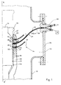
- a high-voltage, quick-cut, shielded circuit breaker comprises a sealed casing 10, the internal compartment 12 of which is filled with an insulating gas with high dielectric strength, in particular sulfur hexafluoride under pressure.
- the circuit breaker is fitted with a self-blowing piston-cylinder device capable of generating a flow of blown gas expelled towards the cut-off interval to extinguish the arc drawn between the contacts in the separated position.
- the circuit breaker is equipped with an optical sensor 14 arranged inside the compartment 12 to determine the speed and the location of the movable contact 16 movable in the direction of the axis XX 'between the extreme positions of opening (solid lines) and closing (dotted lines).
- the sensor 14 comprises a reading system 17 by optical exploration of a plurality of teeth 18 or bosses staggered in the direction of the axis XX 'by forming a rack 20 arranged on the lateral surface of the mobile blowing cylinder 22, mechanically secured to the movable contact 16.
- the reading system 17 is carried by a rigid support 24 insensitive to lateral vibrations of the breaking chamber, and extending along the rack 20 outside the cylinder 22.
- the fixed support 24 is provided with orifices 26 for housing the system 17 comprising three read heads 28, 30, 32, superimposed offset axially from one another and arranged opposite the teeth 18 of the rack 20.
- the opposite end of each read head 28, 30, 32 is connected to an external measurement and processing device 33 by means of a fiber optic transmission cable 34, passing through the cover 36 of the casing 10 by means a sealing plug 38.
- the three heads 28, 30, 32 and their optical transmission cables 34 being identical, only the central head 30 will be described in detail below.
- the emitting and receiving fibers are separated in the plug 38.
- Each transmission cable 34 comprises a core 39 provided with emitting fibers 40 supplied with light by an external light source42, in particular a lamp or an opto-electronic diode member, and fibers receptors 44 connected to a photoelectric element (not shown) integrated in the processing device 33.
- the concentric arrangement of the receiving fibers 44 around the emitting fibers 40 at the level of the read head 30 (FIG. 4) makes it possible to increase the precision of the sensor 14.
- the cable 34 is flexible and has a shape of length close to twice the distance separating the casing 10 from the read head 30, so as not to extend parallel to the lines of the electric field.
- the optical fibers 40, 44 and the core 39 have a diameter of 250 microns and are made of a plastic material based on methyl methacrylate surrounded by a fluoropolymer.
- the core 39 is protected by a tubular polyethylene sheath 46 pierced with a plurality of holes (not shown) allowing the impregnation of SF6 gas between the sheath 46 and the fibers 40, 44 of the core 39. These holes are drilled in the vicinity of the plug 38 where the electric field is the weakest.
- the rigid support 24 of the reading system 17 has a crescent-shaped cross section (FIG. 3) with rounded edges matching the lateral surface of the self-blowing cylinder 22 so as to cast its shadow on the reading heads 28, 30, 32, making the sensor insensitive to luminous parasites, in particular to arc light.
- a crown of bristles47, fixed on the support 24, surrounds the heads 28, 30 and 32 and is flush with the surface of the teeth 18. These opaque bristles 47 protect the read heads from arc light and deposits of dust.
- the rack 20 of the self-blowing cylinder 22 comprises a succession of trapezoidal teeth 18 of alternating coloring such that each tooth 18 has a brilliant projecting edge 48 separated from the adjacent edge by a bottom 50 covered by a layer of black paint or a coating obtained by anodization.
- the radial interval between the bottom 50 and the edge 48 of the teeth 18 is large enough to make the sensor 14 insensitive to dust deposits on the rack 20.
- the upper end 52 and lower 54 teeth of the rack 20 protrude intermediate teeth 18 and cooperate respectively with the read heads 28, 32 to indicate the end-of-travel opening and closing positions of the moving part of the circuit breaker.
- These read heads 28, 32 limit switches are arranged in the same plane parallel to the axis XX 'and radially set back from the central read head 30, intended for measuring the speed of the cylinder 22.
- the radial gap between the intermediate teeth 18 of the rack 20 and the central read head 30 is less than that formed by the teeth 18 when they pass in front of the end read heads 28, 32 during the movement of the moving assembly between the extreme closing and opening positions.
- the read heads 28, 32 limit switches are insensitive to the movement of the intermediate teeth 18 of the rack 20, and only detect the passage of the end teeth 52 and 54 to signal in the device 33 the identification of the movable contact, respectively opening and closing limit switch position.
- the invention is of course in no way limited to the mode of implementation more particularly described and shown in the accompanying drawings, but it extends on the contrary to any variant remaining within the framework of electrotechnical equivalences, in particular that in which the rack 20 would be arranged on another member of the mobile assembly different from the self-blowing cylinder 22 or that in which a single optical read head, for example 30, would be used to indicate both the speed and the location of the mobile contact 16
- the intermediate teeth 18 of the rack 20 and the teeth ends 52, 54 then have different shapes or dimensions allowing the identification of the data by the processing device 33.
Landscapes
- Physics & Mathematics (AREA)
- General Physics & Mathematics (AREA)
- Engineering & Computer Science (AREA)
- Electromagnetism (AREA)
- Power Engineering (AREA)
- Gas-Insulated Switchgears (AREA)
- Photometry And Measurement Of Optical Pulse Characteristics (AREA)
Applications Claiming Priority (2)
| Application Number | Priority Date | Filing Date | Title |
|---|---|---|---|
| FR7918756A FR2461953A1 (fr) | 1979-07-16 | 1979-07-16 | Capteur optique de vitesse et de reperage d'un organe mobile de disjoncteur electrique haute tension |
| FR7918756 | 1979-07-16 |
Publications (2)
| Publication Number | Publication Date |
|---|---|
| EP0022728A1 EP0022728A1 (fr) | 1981-01-21 |
| EP0022728B1 true EP0022728B1 (fr) | 1982-11-24 |
Family
ID=9228088
Family Applications (1)
| Application Number | Title | Priority Date | Filing Date |
|---|---|---|---|
| EP19800401061 Expired EP0022728B1 (fr) | 1979-07-16 | 1980-07-15 | Disjoncteur électrique haute tension à indicateur de l'état de fonctionnement |
Country Status (3)
| Country | Link |
|---|---|
| EP (1) | EP0022728B1 (https=) |
| DE (1) | DE3061151D1 (https=) |
| FR (1) | FR2461953A1 (https=) |
Families Citing this family (5)
| Publication number | Priority date | Publication date | Assignee | Title |
|---|---|---|---|---|
| EP0078870A1 (en) * | 1981-11-10 | 1983-05-18 | Lionel Ivor Alfred Taylor | Improvements in or relating to flowmeters |
| FR2521311B1 (fr) * | 1982-02-11 | 1986-04-18 | Sfena | Transducteur optique numerique a transmission par fibres optiques |
| JPS59151014A (ja) * | 1982-12-10 | 1984-08-29 | フオ−ド・エアロスペイス・アンド・コミユニケイシヨンズ・コ−ポレイシヨン | ジヤイロスコ−プ式取付けロ−タ用オプチカルフアイバ回転センサ |
| JPH0432119A (ja) * | 1990-05-24 | 1992-02-04 | Mitsubishi Electric Corp | 開閉器の主接触子の速度判別方法 |
| AU6010600A (en) * | 1999-11-08 | 2001-06-06 | Ballado Investments, Inc. | Device for the optical detection and measurement of linear movements |
Family Cites Families (4)
| Publication number | Priority date | Publication date | Assignee | Title |
|---|---|---|---|---|
| US3575129A (en) * | 1968-12-04 | 1971-04-13 | Int Harvester Co | Rotation monitor |
| GB1312797A (en) * | 1970-08-11 | 1973-04-04 | Girling Ltd | Vehicle braking systems |
| DE2161281A1 (de) * | 1971-02-11 | 1972-08-24 | Liebknecht Transformat | Anordnung zur Meldung oder Anzeige der Schaltstellung von Hochspannungsschaltern |
| FR2191723A5 (https=) * | 1972-06-30 | 1974-02-01 | Schlumberger Compteurs |
-
1979
- 1979-07-16 FR FR7918756A patent/FR2461953A1/fr active Granted
-
1980
- 1980-07-15 DE DE8080401061T patent/DE3061151D1/de not_active Expired
- 1980-07-15 EP EP19800401061 patent/EP0022728B1/fr not_active Expired
Also Published As
| Publication number | Publication date |
|---|---|
| DE3061151D1 (en) | 1982-12-30 |
| FR2461953B1 (https=) | 1983-04-22 |
| EP0022728A1 (fr) | 1981-01-21 |
| FR2461953A1 (fr) | 1981-02-06 |
Similar Documents
| Publication | Publication Date | Title |
|---|---|---|
| EP0543732A1 (fr) | Disjoncteur à vide muni de moyens d'autodiagnostic | |
| EP2463883B1 (fr) | Dispositif de détection de la perte de vide dans un appareil de coupure à vide et appareil de coupure à vide comportant un tel dispositif | |
| JPS6346933B2 (https=) | ||
| EP0022728B1 (fr) | Disjoncteur électrique haute tension à indicateur de l'état de fonctionnement | |
| EP0291404A1 (fr) | Dispositif pour la détection de vibrations comportant une fibre optique multimode comme élément sensible | |
| EP0327420A1 (fr) | Dispositif et procédé de mesure d'une impulsion brève de rayonnement ou d'une impulsion brève électrique | |
| EP0247909A1 (fr) | Capteur à fibre optique | |
| CN109283143A (zh) | 一种红外、紫外、可见光的图像处理融合系统及方法 | |
| FR2479987A1 (fr) | Sonde a emission de signal pour dispositif de detection de vitesse de turbine | |
| FR2473708A1 (fr) | Procede et dispositif de mesure optique de la temperature et procede de realisation d'une sonde appropriee | |
| CA2108185C (fr) | Dispositif support d'une sonde de detection et de localisation de defauts eventuels a l'interieur d'un alesage | |
| FR2476849A1 (fr) | Appareil pour la mesure d'un champ electrique | |
| EP0813068B1 (fr) | Dispositif pour détecter et localiser des anomalies de la protection électromagnétique d'un système | |
| EP0285469B1 (fr) | Procédé et dispositif de détection et de correction de la position d'électrodes, notamment utilisées dans des appareils de génération d'ondes de choc utilisant un doigt palpeur amené au point focal en particulier constitué par la tige d'un vérin | |
| FR2758393A1 (fr) | Sonde a courants de foucault | |
| CH681660A5 (en) | Electrical discharger detector for sulphur hexa:fluoride enclosure | |
| FR2498337A1 (fr) | Procede d'illumination du sol et de calcul de la constante dielectrique et de la conductivite de celui-ci au moyen d'une impulsion electromagnetique, et simulateur pour la mise en oeuvre de ce procede | |
| EP2994920A1 (fr) | Surcouche destinee a recouvrir un objet, notamment un cable, pour la detection et/ou la localisation d'un defaut a sa surface | |
| FR3049351B1 (fr) | Dispositif d'essais de decharges partielles sur les cables | |
| CA2216568A1 (fr) | Dispositif de surveillance pour un cable a isolation gazeuse | |
| EP0217745B1 (fr) | Dispositif de contrôle de cigarettes groupées en vue de leur empaquetage et appareil à empaqueter les cigarettes équipé de ce dispositif de contrôle | |
| FR3101195A1 (fr) | Liaison électrique comprenant un dispositif optronique de protection électrique. | |
| CA2035449C (fr) | Dispositif pour le controle d'etancheite des reseaux de cables a gaine metallique | |
| CH645765A5 (fr) | Procede pour detecter l'interruption de la transmission de signaux lumineux et dispositif pour la mise en oeuvre de ce procede. | |
| EP0788207B1 (fr) | Dispositif de détection d'arc interne pour câble électrique à isolation gazeuse |
Legal Events
| Date | Code | Title | Description |
|---|---|---|---|
| PUAI | Public reference made under article 153(3) epc to a published international application that has entered the european phase |
Free format text: ORIGINAL CODE: 0009012 |
|
| AK | Designated contracting states |
Designated state(s): BE CH DE GB IT NL SE |
|
| 17P | Request for examination filed |
Effective date: 19810518 |
|
| ITF | It: translation for a ep patent filed | ||
| GRAA | (expected) grant |
Free format text: ORIGINAL CODE: 0009210 |
|
| AK | Designated contracting states |
Designated state(s): BE CH DE GB IT NL SE |
|
| REF | Corresponds to: |
Ref document number: 3061151 Country of ref document: DE Date of ref document: 19821230 |
|
| PGFP | Annual fee paid to national office [announced via postgrant information from national office to epo] |
Ref country code: CH Payment date: 19840712 Year of fee payment: 5 |
|
| PGFP | Annual fee paid to national office [announced via postgrant information from national office to epo] |
Ref country code: BE Payment date: 19840930 Year of fee payment: 5 |
|
| PGFP | Annual fee paid to national office [announced via postgrant information from national office to epo] |
Ref country code: NL Payment date: 19870731 Year of fee payment: 8 |
|
| PGFP | Annual fee paid to national office [announced via postgrant information from national office to epo] |
Ref country code: SE Payment date: 19890619 Year of fee payment: 10 |
|
| PG25 | Lapsed in a contracting state [announced via postgrant information from national office to epo] |
Ref country code: GB Effective date: 19890715 |
|
| PG25 | Lapsed in a contracting state [announced via postgrant information from national office to epo] |
Ref country code: LI Effective date: 19890731 Ref country code: CH Effective date: 19890731 Ref country code: BE Effective date: 19890731 |
|
| BERE | Be: lapsed |
Owner name: MERLIN GERIN Effective date: 19890731 |
|
| PG25 | Lapsed in a contracting state [announced via postgrant information from national office to epo] |
Ref country code: NL Effective date: 19900201 |
|
| NLV4 | Nl: lapsed or anulled due to non-payment of the annual fee | ||
| REG | Reference to a national code |
Ref country code: CH Ref legal event code: PL |
|
| GBPC | Gb: european patent ceased through non-payment of renewal fee | ||
| PG25 | Lapsed in a contracting state [announced via postgrant information from national office to epo] |
Ref country code: SE Effective date: 19900716 |
|
| ITTA | It: last paid annual fee | ||
| PGFP | Annual fee paid to national office [announced via postgrant information from national office to epo] |
Ref country code: DE Payment date: 19910830 Year of fee payment: 12 |
|
| PG25 | Lapsed in a contracting state [announced via postgrant information from national office to epo] |
Ref country code: DE Effective date: 19930602 |
|
| EUG | Se: european patent has lapsed |
Ref document number: 80401061.9 Effective date: 19910402 |
|
| PLBE | No opposition filed within time limit |
Free format text: ORIGINAL CODE: 0009261 |
|
| STAA | Information on the status of an ep patent application or granted ep patent |
Free format text: STATUS: NO OPPOSITION FILED WITHIN TIME LIMIT |