EP0022692B1 - Turboréacteur multiflux à taux de dilution pilotable - Google Patents
Turboréacteur multiflux à taux de dilution pilotable Download PDFInfo
- Publication number
- EP0022692B1 EP0022692B1 EP80400934A EP80400934A EP0022692B1 EP 0022692 B1 EP0022692 B1 EP 0022692B1 EP 80400934 A EP80400934 A EP 80400934A EP 80400934 A EP80400934 A EP 80400934A EP 0022692 B1 EP0022692 B1 EP 0022692B1
- Authority
- EP
- European Patent Office
- Prior art keywords
- turbine
- high pressure
- low pressure
- flow
- cold
- Prior art date
- Legal status (The legal status is an assumption and is not a legal conclusion. Google has not performed a legal analysis and makes no representation as to the accuracy of the status listed.)
- Expired
Links
- 238000011144 upstream manufacturing Methods 0.000 claims description 12
- 239000012895 dilution Substances 0.000 claims description 10
- 238000010790 dilution Methods 0.000 claims description 10
- 230000006835 compression Effects 0.000 claims description 6
- 238000007906 compression Methods 0.000 claims description 6
- 208000031968 Cadaver Diseases 0.000 description 6
- 230000004907 flux Effects 0.000 description 6
- 230000000694 effects Effects 0.000 description 2
- 239000000446 fuel Substances 0.000 description 2
- 238000010438 heat treatment Methods 0.000 description 2
- 239000000463 material Substances 0.000 description 2
- 239000000243 solution Substances 0.000 description 2
- 238000002485 combustion reaction Methods 0.000 description 1
- 239000012530 fluid Substances 0.000 description 1
- 239000007789 gas Substances 0.000 description 1
- 210000003462 vein Anatomy 0.000 description 1
Images

Classifications
-
- F—MECHANICAL ENGINEERING; LIGHTING; HEATING; WEAPONS; BLASTING
- F02—COMBUSTION ENGINES; HOT-GAS OR COMBUSTION-PRODUCT ENGINE PLANTS
- F02K—JET-PROPULSION PLANTS
- F02K3/00—Plants including a gas turbine driving a compressor or a ducted fan
- F02K3/02—Plants including a gas turbine driving a compressor or a ducted fan in which part of the working fluid by-passes the turbine and combustion chamber
- F02K3/04—Plants including a gas turbine driving a compressor or a ducted fan in which part of the working fluid by-passes the turbine and combustion chamber the plant including ducted fans, i.e. fans with high volume, low pressure outputs, for augmenting the jet thrust, e.g. of double-flow type
- F02K3/075—Plants including a gas turbine driving a compressor or a ducted fan in which part of the working fluid by-passes the turbine and combustion chamber the plant including ducted fans, i.e. fans with high volume, low pressure outputs, for augmenting the jet thrust, e.g. of double-flow type controlling flow ratio between flows
Definitions
- the invention relates to a double-flow turbojet (single-body or double-body) with separate or mixed flows in which the evolution of the dilution rate as a function of flight conditions is linked to the cycle.
- the metering of the fuel or the values of the nozzle sections have only a small effect on this development.
- the dilution rate increases whereas it would be highly desirable for it to decrease in order to obtain the maximum thrust in a given space requirement.
- turbofan engines in which the dilution rate is modified according to the flight conditions, by the introduction, in the secondary channel, of a burner.
- These turbojets are equipped with a turbine placed in a secondary flow and subjected to the action of hot gases.
- This turbine is preceded by a distributor stage which makes it possible to obtain optimal conditions by adapting the passage section.
- it is necessary, in order to pass from operation at high dilution rate to operation at low dilution rate, to re-optimize the operating parameters disturbed by the commissioning of the burner, by opening the section of the distributor placed in the secondary flow. This arrangement leads to a transfer of energy in thermal form.
- FR-A-1 520 460 it is known from FR-A-1 520 460 to produce a multi-flow turbojet engine comprising at least one rotating body directly driven by aerodynamic surfaces mechanically integral with said body, disposed in the secondary flow and acting by expansion of the fluid , in which the energy of the secondary flow is increased by an increase in the compression ratio, a distributor whose vanes are of variable setting being placed upstream of said aerodynamic surfaces.
- the purpose of this arrangement is to allow the compression rate generally obtained, which is around 25, to be exceeded, without having to use a triple body machine.
- This solution therefore consists in using, in addition to the usual compression group, one or more mechanically independent compressors, directly driven by the aerodynamic surfaces placed in the secondary vein. In such arrangements, this or these additional compressors are not mechanically linked either to the compression group or to the turbine placed in the primary flow and driving it.
- the present invention relates to a multiflow turbojet engine with controllable dilution rate of the above type comprising at least one rotating body driven by aerodynamic surfaces mechanically integral with said surfaces disposed in the cold secondary flow and acting by expansion of the air, l energy of said secondary flows being increased by an increase in the compression ratio, a distributor whose vanes are orientable between two extreme positions being placed upstream of said aerodynamic surfaces.
- this multi-flow turbojet engine with controllable dilution rate is characterized in that the rotating body is also driven by a turbine arranged in the hot primary flow.
- FIG. 1 a turbofan engine has been shown which comprises a low pressure body consisting of a low pressure blower 1 with one or more stages driven by a low pressure turbine 2 and a high pressure body consisting of a double compressor 3 flow of one or more stages driven in rotation by a high pressure turbine 4.
- An internal annular conduit 5 is traversed by the primary flow and an external annular conduit 6 is traversed by the secondary flow, the internal conduit 5 traversed by the primary flow contains a part 3a of the high pressure compressor, a combustion chamber 7 and the turbines 4 and 2.
- the part 3b of the high pressure compressor overcompresses the secondary flow in the duct 6 before expanding it in a cold turbine 8 arranged at the periphery of the blades of the low pressure turbine 2.
- the additional energy supplied to the secondary flow by the overcompression is thus transmitted in mechanical form to the rotating body by the expansion of the cold turbine.
- Upstream of the cold turbine 8 is arranged a distributor 9 with variable setting, the weakest setting, taken as origin, being that which corresponds, for the distributor, to the largest passage section.
- N2 f (N1, Z, M, a) which for each altitude Z, for each number of Mach M and for a position a of the fuel control lever, fixes, for each value N1, a value N2 and from the above, a ratio of primary and secondary flow rates.
- N1, Z, M, a f (N1, Z, M, a) which for each altitude Z, for each number of Mach M and for a position a of the fuel control lever, fixes, for each value N1, a value N2 and from the above, a ratio of primary and secondary flow rates.
- the turbojet engine comprises a high pressure body which has a mechanical connection with the aerodynamic surfaces placed in the secondary flow.
- this material contact is obtained by the compressor 3b.
- variable energy obtained by varying the setting of the distributor of the cold turbine 8
- the transfer of variable energy is accompanied by a variation in the speed N2 of rotation of the high pressure body.
- N1 of rotation of the low pressure body with: 0 being the setting of the orientable distributor 9.
- FIG. 2 shows another embodiment of the turbojet engine in which the low pressure body consists of a double-flow compressor 10 which is driven by a low pressure turbine 11.
- the high pressure body consists of a compressor 12 high pressure single flow which is driven by a high pressure turbine 13.
- the high pressure turbine 13 is provided at its periphery with a cold turbine 14 arranged in the duct 6 of secondary flow and preceded by a distributor 15 with variable setting.
- the secondary flow is supercharged in the low pressure compressor 10 and expanded in the cold turbine 14 located at the periphery of the blade of the high pressure turbine.
- the secondary flow is supercharged in the low pressure compressor 10 and expanded in the cold turbine 14 located at the periphery of the blade of the high pressure turbine.
- FIG 3 there is shown a turbojet in which the low pressure or blower compressor 1 is driven by a turbine 2 and the high pressure compressor 3 with double flow is driven by a turbine 13, as in the embodiment shown in Figure 1.
- a double-flow single-body turbojet engine which consists of a double-flow compressor 16 comprising a high pressure part 16b and a low pressure part 16a which is driven by a two-stage turbine 17.18 the turbine 18 is provided at its periphery with a cold turbine 19 which is disposed in the secondary flow duct 6, said turbine 19 comprising upstream a distributor 20 with adjustable setting.
- the unibody is a high pressure body. It is obvious that the influence of the angle in the case of this embodiment is weaker than in the previous cases.
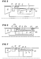
- FIG. 5 shows a turbojet engine which comprises a low-flow double-pressure compressor which is driven by a turbine 22, and a high-pressure compressor 23 driven by a turbine 24.
- a cold turbine 25 is disposed upstream of the high pressure compressor 23 and it is mechanically connected to the high pressure body comprising the compressor 23.
- the cold turbine 25 is provided upstream of a distributor 26 with adjustable setting.
- the element 27 disposed between the compressor 21 and the turbine 25 is used as a structural support member and not as an aerodynamic member.
- FIG. 6 is shown a combination of the solutions represented in FIGS. 5 and 1.
- the turbojet engine has a low pressure body 21 directly driven by a turbine 22 and a high pressure double flow body (23a, 23b ) mechanically independent of the first and directly driven by a turbine 24, a cold turbine 28 mechanically secured to the body 21 being provided with an adjustable distributor (29).
- a cold turbine (28), mechanically secured to the body 23 and provided with an adjustable distributor 26, is arranged upstream of the flow sharing line of this high pressure double flow compressor.
- FIG. 7 there is shown another embodiment of a turbojet in which the low pressure compressors 21 and high pressure 23 and the cold turbine 25 are driven by a turbine 22 and form a single driven body.
Landscapes
- Engineering & Computer Science (AREA)
- Chemical & Material Sciences (AREA)
- Combustion & Propulsion (AREA)
- Mechanical Engineering (AREA)
- General Engineering & Computer Science (AREA)
- Structures Of Non-Positive Displacement Pumps (AREA)
- Control Of Turbines (AREA)
Applications Claiming Priority (2)
| Application Number | Priority Date | Filing Date | Title |
|---|---|---|---|
| FR7918317A FR2461820A1 (fr) | 1979-07-16 | 1979-07-16 | Turboreacteur multiflux a taux de dilution pilotable |
| FR7918317 | 1979-07-16 |
Publications (2)
| Publication Number | Publication Date |
|---|---|
| EP0022692A1 EP0022692A1 (fr) | 1981-01-21 |
| EP0022692B1 true EP0022692B1 (fr) | 1986-09-10 |
Family
ID=9227895
Family Applications (1)
| Application Number | Title | Priority Date | Filing Date |
|---|---|---|---|
| EP80400934A Expired EP0022692B1 (fr) | 1979-07-16 | 1980-06-24 | Turboréacteur multiflux à taux de dilution pilotable |
Country Status (4)
| Country | Link |
|---|---|
| US (1) | US4376375A (Direct) |
| EP (1) | EP0022692B1 (Direct) |
| DE (1) | DE3071749D1 (Direct) |
| FR (1) | FR2461820A1 (Direct) |
Cited By (1)
| Publication number | Priority date | Publication date | Assignee | Title |
|---|---|---|---|---|
| US11846196B2 (en) | 2020-02-21 | 2023-12-19 | Rtx Corporation | After-fan system with electrical motor for gas turbine engines |
Families Citing this family (24)
| Publication number | Priority date | Publication date | Assignee | Title |
|---|---|---|---|---|
| US5694767A (en) * | 1981-11-02 | 1997-12-09 | General Electric Company | Variable slot bypass injector system |
| US5003766A (en) * | 1984-10-10 | 1991-04-02 | Paul Marius A | Gas turbine engine |
| GB2246171B (en) * | 1986-06-21 | 1992-04-08 | British Aerospace | Improvements in or related to gas turbine engines |
| GB2193999B (en) * | 1986-08-12 | 1990-08-29 | Rolls Royce Plc | Gas turbine engine with variable bypass means |
| US5305599A (en) * | 1991-04-10 | 1994-04-26 | General Electric Company | Pressure-ratio control of gas turbine engine |
| DE4220273A1 (de) * | 1992-06-20 | 1993-12-23 | Asea Brown Boveri | Gasturbinen-Anlage |
| US5794432A (en) * | 1996-08-27 | 1998-08-18 | Diversitech, Inc. | Variable pressure and variable air flow turbofan engines |
| AU5581500A (en) * | 1999-07-13 | 2001-01-30 | Osobov, Viktor Isaakovich | Heat engine |
| RU2241833C2 (ru) * | 2002-12-09 | 2004-12-10 | Шабанов Анатолий Иванович | Паровая турбина с вращающимся сопловым аппаратом |
| GB0314123D0 (en) * | 2003-06-18 | 2003-07-23 | Rolls Royce Plc | A gas turbine engine |
| US8161728B2 (en) * | 2007-06-28 | 2012-04-24 | United Technologies Corp. | Gas turbines with multiple gas flow paths |
| US8104265B2 (en) * | 2007-06-28 | 2012-01-31 | United Technologies Corporation | Gas turbines with multiple gas flow paths |
| US9359960B2 (en) * | 2007-06-28 | 2016-06-07 | United Technologies Corporation | Gas turbines with multiple gas flow paths |
| US8082727B2 (en) * | 2008-02-26 | 2011-12-27 | United Technologies Corporation | Rear propulsor for a variable cycle gas turbine engine |
| US20110146228A1 (en) * | 2009-12-21 | 2011-06-23 | John Lewis Baughman | Power extraction system |
| US20110146289A1 (en) * | 2009-12-21 | 2011-06-23 | John Lewis Baughman | Power extraction method |
| US9157366B2 (en) | 2012-05-30 | 2015-10-13 | United Technologies Corporation | Adaptive fan with cold turbine |
| US9488101B2 (en) | 2013-03-14 | 2016-11-08 | United Technologies Corporation | Adaptive fan reverse core geared turbofan engine with separate cold turbine |
| US9850822B2 (en) | 2013-03-15 | 2017-12-26 | United Technologies Corporation | Shroudless adaptive fan with free turbine |
| US10711702B2 (en) * | 2015-08-18 | 2020-07-14 | General Electric Company | Mixed flow turbocore |
| US10578028B2 (en) | 2015-08-18 | 2020-03-03 | General Electric Company | Compressor bleed auxiliary turbine |
| CN109538376B (zh) * | 2018-11-07 | 2021-01-26 | 中国航发湖南动力机械研究所 | 飞行器及其发动机 |
| US11994089B2 (en) * | 2019-04-10 | 2024-05-28 | Rtx Corporation | After-fan system for a gas turbine engine |
| US12078102B2 (en) * | 2022-09-23 | 2024-09-03 | Rtx Corporation | Air recuperated engine with air reinjection |
Family Cites Families (10)
| Publication number | Priority date | Publication date | Assignee | Title |
|---|---|---|---|---|
| CH270351A (de) * | 1951-03-27 | 1950-08-31 | Power Jets Res & Dev Ltd | Gasturbinen-Kraftanlage. |
| GB838602A (en) * | 1957-03-06 | 1960-06-22 | Power Jets Res & Dev Ltd | Improvements in or relating to gas turbine plant |
| GB980306A (en) * | 1963-05-10 | 1965-01-13 | Rolls Royce | Gas turbine engine |
| FR1377306A (fr) * | 1963-05-31 | 1964-11-06 | Rolls Royce | Compresseur ou ventilateur à courants axiaux et moteur à turbine à gaz équipé de cet appareil |
| GB1069033A (en) * | 1965-01-30 | 1967-05-17 | Rolls Royce | Improvements in or relating to gas turbine jet propulsion engines |
| GB1126707A (en) * | 1966-08-24 | 1968-09-11 | Rolls Royce | By-pass gas turbine jet propulsion engine |
| FR1520460A (fr) * | 1967-01-11 | 1968-04-12 | Snecma | Perfectionnements aux turboréacteurs à flux multiples |
| GB1229007A (Direct) * | 1968-12-04 | 1971-04-21 | ||
| FR2316443A1 (fr) * | 1975-07-02 | 1977-01-28 | Snecma | Variateur du taux de dilution d'un turboreacteur multiflux |
| US4054030A (en) * | 1976-04-29 | 1977-10-18 | General Motors Corporation | Variable cycle gas turbine engine |
-
1979
- 1979-07-16 FR FR7918317A patent/FR2461820A1/fr active Granted
-
1980
- 1980-06-24 EP EP80400934A patent/EP0022692B1/fr not_active Expired
- 1980-06-24 DE DE8080400934T patent/DE3071749D1/de not_active Expired
- 1980-07-16 US US06/169,465 patent/US4376375A/en not_active Expired - Lifetime
Cited By (1)
| Publication number | Priority date | Publication date | Assignee | Title |
|---|---|---|---|---|
| US11846196B2 (en) | 2020-02-21 | 2023-12-19 | Rtx Corporation | After-fan system with electrical motor for gas turbine engines |
Also Published As
| Publication number | Publication date |
|---|---|
| FR2461820B1 (Direct) | 1983-03-11 |
| DE3071749D1 (en) | 1986-10-16 |
| EP0022692A1 (fr) | 1981-01-21 |
| US4376375A (en) | 1983-03-15 |
| FR2461820A1 (fr) | 1981-02-06 |
Similar Documents
| Publication | Publication Date | Title |
|---|---|---|
| EP0022692B1 (fr) | Turboréacteur multiflux à taux de dilution pilotable | |
| US10662803B2 (en) | Aerofoil body | |
| FR3028888A1 (fr) | Dispositif de refroidissement pour une turbomachine alimente par un circuit de decharge | |
| FR3051219B1 (fr) | Aube de turbomachine, telle par exemple qu'un turboreacteur ou un turbopropulseur d'avion | |
| WO2021191528A1 (fr) | Turbomachine à double flux comprenant un dispositif de régulation du débit de fluide de refroidissement | |
| EP1621744B1 (fr) | Ensemble de cône d'entrée d'une turbomachine et d'un arbre portant des aubes de soufflante | |
| EP1956226B1 (fr) | Dispositif de décharge pour un turboréacteur, et turboréacteur le comportant | |
| EP3722559A1 (fr) | Turbomachine pour un aeronef | |
| EP0473494B1 (fr) | Circuit d'alimentation en carburant d'un turbo-moteur | |
| FR3069020A1 (fr) | Compresseur de turbomachine a calages variables | |
| EP4127405B1 (fr) | Turbomachine avec dispositif de refroidissement et de pressurisation d'une turbine | |
| EP3847344A1 (fr) | Distributeur d'une turbine radiale de turbomachine, turbomachine comprenant un tel distributeur et système de conditionnement d'air comprenant une telle turbomachine | |
| EP4256187B1 (fr) | Ecope pour une turbomachine d'aeronef | |
| FR3108657A1 (fr) | Rotor de turbine comprenant un dispositif de régulation du débit de fluide de refroidissement et turbomachine comprenant un tel rotor | |
| EP3642465B1 (fr) | Agencement de deux turbomoteurs | |
| FR3108658A1 (fr) | Rotor de turbine comprenant un dispositif de régulation du débit de fluide de refroidissement et turbomachine comprenant un tel rotor | |
| FR3108659A1 (fr) | Rotor de turbine comprenant un dispositif de régulation du débit de fluide de refroidissement et turbomachine comprenant un tel rotor | |
| FR3114610A1 (fr) | Aube d’entrée d'air pour une turbomachine d’aéronef | |
| US10570762B2 (en) | Vane strut positioning and securing systems including locking washers | |
| CA2885343C (en) | Shaft assembly of a gas turbine engine and method of controlling flow therein | |
| EP1359309A1 (fr) | Turbine à gaz comportant un dispositif de mélange de gaz à lobes et à tubes | |
| FR2991388A1 (fr) | Turbomachine pour moteur d'aeronef | |
| WO2025012539A1 (fr) | Ensemble propulsif d'aeronef et procede de gestion thermique | |
| WO2025078764A1 (fr) | Turbomachine d'aeronef comprenant une pompe a chaleur | |
| FR3155028A1 (fr) | Ensemble pour turbomachine d’aeronef comprenant un aubage directeur de sortie traverse par un canal d’air de refroidissement |
Legal Events
| Date | Code | Title | Description |
|---|---|---|---|
| PUAI | Public reference made under article 153(3) epc to a published international application that has entered the european phase |
Free format text: ORIGINAL CODE: 0009012 |
|
| 17P | Request for examination filed |
Effective date: 19800702 |
|
| AK | Designated contracting states |
Designated state(s): DE FR GB SE |
|
| GRAA | (expected) grant |
Free format text: ORIGINAL CODE: 0009210 |
|
| AK | Designated contracting states |
Kind code of ref document: B1 Designated state(s): DE FR GB SE |
|
| REF | Corresponds to: |
Ref document number: 3071749 Country of ref document: DE Date of ref document: 19861016 |
|
| PLBE | No opposition filed within time limit |
Free format text: ORIGINAL CODE: 0009261 |
|
| STAA | Information on the status of an ep patent application or granted ep patent |
Free format text: STATUS: NO OPPOSITION FILED WITHIN TIME LIMIT |
|
| 26N | No opposition filed | ||
| EAL | Se: european patent in force in sweden |
Ref document number: 80400934.8 |
|
| PGFP | Annual fee paid to national office [announced via postgrant information from national office to epo] |
Ref country code: DE Payment date: 19960830 Year of fee payment: 17 |
|
| PGFP | Annual fee paid to national office [announced via postgrant information from national office to epo] |
Ref country code: SE Payment date: 19970516 Year of fee payment: 18 |
|
| PGFP | Annual fee paid to national office [announced via postgrant information from national office to epo] |
Ref country code: GB Payment date: 19970616 Year of fee payment: 18 |
|
| PG25 | Lapsed in a contracting state [announced via postgrant information from national office to epo] |
Ref country code: DE Free format text: LAPSE BECAUSE OF NON-PAYMENT OF DUE FEES Effective date: 19980303 |
|
| PGFP | Annual fee paid to national office [announced via postgrant information from national office to epo] |
Ref country code: FR Payment date: 19980528 Year of fee payment: 19 |
|
| PG25 | Lapsed in a contracting state [announced via postgrant information from national office to epo] |
Ref country code: GB Free format text: LAPSE BECAUSE OF NON-PAYMENT OF DUE FEES Effective date: 19980624 |
|
| PG25 | Lapsed in a contracting state [announced via postgrant information from national office to epo] |
Ref country code: SE Free format text: LAPSE BECAUSE OF NON-PAYMENT OF DUE FEES Effective date: 19980625 |
|
| GBPC | Gb: european patent ceased through non-payment of renewal fee |
Effective date: 19980624 |
|
| EUG | Se: european patent has lapsed |
Ref document number: 80400934.8 |
|
| PG25 | Lapsed in a contracting state [announced via postgrant information from national office to epo] |
Ref country code: FR Free format text: THE PATENT HAS BEEN ANNULLED BY A DECISION OF A NATIONAL AUTHORITY Effective date: 19990630 |
|
| REG | Reference to a national code |
Ref country code: FR Ref legal event code: ST |