EP0021976B1 - Relais électromagnétique - Google Patents
Relais électromagnétique Download PDFInfo
- Publication number
- EP0021976B1 EP0021976B1 EP19800400877 EP80400877A EP0021976B1 EP 0021976 B1 EP0021976 B1 EP 0021976B1 EP 19800400877 EP19800400877 EP 19800400877 EP 80400877 A EP80400877 A EP 80400877A EP 0021976 B1 EP0021976 B1 EP 0021976B1
- Authority
- EP
- European Patent Office
- Prior art keywords
- plates
- plate
- support block
- electromagnetic relay
- fixed
- Prior art date
- Legal status (The legal status is an assumption and is not a legal conclusion. Google has not performed a legal analysis and makes no representation as to the accuracy of the status listed.)
- Expired
Links
- 230000000295 complement effect Effects 0.000 claims description 4
- 238000009826 distribution Methods 0.000 claims description 4
- 240000008042 Zea mays Species 0.000 description 3
- 239000011810 insulating material Substances 0.000 description 3
- 210000004027 cell Anatomy 0.000 description 2
- 239000011248 coating agent Substances 0.000 description 2
- 238000000576 coating method Methods 0.000 description 2
- 239000002184 metal Substances 0.000 description 2
- 238000000034 method Methods 0.000 description 2
- 238000003825 pressing Methods 0.000 description 2
- 208000029152 Small face Diseases 0.000 description 1
- 230000015556 catabolic process Effects 0.000 description 1
- 239000004020 conductor Substances 0.000 description 1
- 238000005520 cutting process Methods 0.000 description 1
- 238000006731 degradation reaction Methods 0.000 description 1
- 238000005553 drilling Methods 0.000 description 1
- 230000000694 effects Effects 0.000 description 1
- 238000004519 manufacturing process Methods 0.000 description 1
- 239000000463 material Substances 0.000 description 1
- 238000000465 moulding Methods 0.000 description 1
- 238000007747 plating Methods 0.000 description 1
- 230000001681 protective effect Effects 0.000 description 1
- 230000002787 reinforcement Effects 0.000 description 1
- 238000003860 storage Methods 0.000 description 1
- 238000002604 ultrasonography Methods 0.000 description 1
Images


Classifications
-
- H—ELECTRICITY
- H01—ELECTRIC ELEMENTS
- H01H—ELECTRIC SWITCHES; RELAYS; SELECTORS; EMERGENCY PROTECTIVE DEVICES
- H01H50/00—Details of electromagnetic relays
- H01H50/02—Bases; Casings; Covers
- H01H50/04—Mounting complete relay or separate parts of relay on a base or inside a case
- H01H50/041—Details concerning assembly of relays
-
- H—ELECTRICITY
- H01—ELECTRIC ELEMENTS
- H01H—ELECTRIC SWITCHES; RELAYS; SELECTORS; EMERGENCY PROTECTIVE DEVICES
- H01H50/00—Details of electromagnetic relays
- H01H50/54—Contact arrangements
- H01H50/56—Contact spring sets
-
- H—ELECTRICITY
- H01—ELECTRIC ELEMENTS
- H01H—ELECTRIC SWITCHES; RELAYS; SELECTORS; EMERGENCY PROTECTIVE DEVICES
- H01H1/00—Contacts
- H01H1/12—Contacts characterised by the manner in which co-operating contacts engage
- H01H1/14—Contacts characterised by the manner in which co-operating contacts engage by abutting
- H01H1/24—Contacts characterised by the manner in which co-operating contacts engage by abutting with resilient mounting
- H01H1/26—Contacts characterised by the manner in which co-operating contacts engage by abutting with resilient mounting with spring blade support
- H01H2001/265—Contacts characterised by the manner in which co-operating contacts engage by abutting with resilient mounting with spring blade support having special features for supporting, locating or pre-stressing the contact blade springs
-
- H—ELECTRICITY
- H01—ELECTRIC ELEMENTS
- H01H—ELECTRIC SWITCHES; RELAYS; SELECTORS; EMERGENCY PROTECTIVE DEVICES
- H01H50/00—Details of electromagnetic relays
- H01H50/64—Driving arrangements between movable part of magnetic circuit and contact
- H01H50/641—Driving arrangements between movable part of magnetic circuit and contact intermediate part performing a rectilinear movement
- H01H50/642—Driving arrangements between movable part of magnetic circuit and contact intermediate part performing a rectilinear movement intermediate part being generally a slide plate, e.g. a card
Definitions
- the invention relates to electromagnetic relays of the stacking type of electrical contact blades, in particular for telecommunications.
- the stacking of the contact blades and the plates requires precise alignment so that the facing contacts at the end of said blades can be established on an optimum surface.
- An approximate centering can be obtained by fixing the stack to the cylinder head of the relay by means of two screws or rivets passing through the blade-insert assembly. This has the disadvantage of requiring a large dimensioning of the blades and a certain clearance between the diameter of the screws and the drilling holes.
- a solution for a more precise alignment of blades of a small size consists in using only one fixing screw for a block of two stacks of blades, said blades of each stack being centered by two insulating pins passing through the assembly blade plates in the axis of symmetry of said blades.
- these insulating pins must be calibrated with precision, which weighs significantly on the cost of the product.
- the patent US-A-2838631 describes a different solution in which a single screw makes it possible to fix a block of two stacks of blades, the block consists of insulating plates which can be inserted one inside the other thanks to transverse recesses and complementary shoulders respectively made on either side of the plates to ensure the positioning of the blades inserted between these nested plates.
- the fixing of the stacking block by a screw or a rivet passing through the central part of the block has the drawback of concentrating the pressure on the central zone of the plates, the lateral parts of which tend to spread out in a fan on either side of the central area.
- German patent provides in particular a central crown flange associated with a flat leaf spring applied between the central crown and the plates as well as a central crown flange and side flaps pressing simultaneously on a leaf spring applied to the platelets.
- Another means of producing stacking blocks consists in coating a part of each strip in molten insulating material in order to obtain a strip-plate and in positioning them according to the preceding solution. Another way is to position the blades of one or more stacks in a special mold and fill the mold with molten insulating material.
- the present invention therefore provides an electromagnetic relay with stacks of fixed and movable electrical contact blades held in at least one support block which is fixed to a yoke of the relay by means of a screw and which consists of interlocking insulating plates one inside the other thanks to transverse recesses and complementary shoulders respectively produced on one and / or the other face of the plates to ensure the positioning in alignment of the contact blades clamped in the recesses by the shoulders under the action of the screw.
- the plates of a support block are assembled in at least two sets, nested and aligned, in each of which the plates are assembled together by means of two retaining fingers carried by the one of them placed at one end of the game in question, the support block being secured to a base, transverse to the cylinder head and integral with this cylinder head, by means of a bar with bent ends and with central part reinforced on which rests on the fixing screw passing through said reinforced central part and said plates in their respective central parts to be screwed into said base so that pressure is distributed over the central part and over the lateral parts of the plates.
- the plates of a support block are assembled in at least two interlocked and aligned sets, in each of which the plates are assembled together by means of two retaining fingers carried by t ' one of them placed at one end of the game in question, the support block being secured to the cylinder head, by means of a U-shaped flange shaped so as to have a central bulge and two lateral bulges so as to be ensured a distribution of the pressure on the central part and on the lateral parts of the pads.
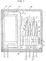
- the relay comprises, integral with the cylinder head 1, a base 2 on which rests a block of stacks of fixed conductive blades 3, 5 and mobile 4 constituting rest-work contacts or RT contacts.
- the conductive strips 3, 4, 5 and their wiring pins 6 are positioned between insulating plates 7, 9, 10, 11 which can be fitted together, some of said plates being extended towards the contact ends of the conductors by an insulating tab 8a, 8b including faces is oblique profile.
- a metal bar 12 fixes the stacking block to the frame of the relay by a screw 13, the end of which is screwed to the base 2.
- the relay is protected by a transparent cover 20 embedded on a base 19.
- the "floating" of the relay in the cover is prohibited in width by the lateral sides of the cylinder head, in length by two pairs of internal ribs 21, 22 with opposite ramps and in height by a shoulder 24 at the bottom of the cover having a bearing on the cylinder head between the bent part of the small face of said cylinder head and the core of the coil.
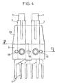
- Fig. 2 shows the stacking block seen in profile. It includes, for example two columns of two rows of blades 3, 4, 5 or four RT contacts.
- the stacking block is formed by two homologous sets J1 and J2 of contiguous and / or nested elements, each of said sets constituting two RT contacts.
- the J2 set is shown with its elements nested while the J1 set is shown with its spaced elements.
- the row of the pair of working contact blades 5 is sandwiched by interlocking means of the plates 9 and 8b.
- the row of the pair of rest contact blades 3 is sandwiched by interlocking means of plates 8a and 7.
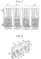
- the intermediate retaining plate 9 or 10 the pallet plates 8a and 8b and the end plate 7 are shown in more detail in FIG. 3.
- the intermediate plate 9 of rectangular shape has on one face two parallel and symmetrical recesses 30 with vertical sides.
- Two retaining fingers 31 molded in the mass of the wafer are each arranged orthogonally to the plane of the wafer; the base of said finger, starting from the bottom of the recess, comprises an annular cup 32.
- the contact blades and the other plates of a stacking set have holes opposite the retaining fingers 31 and are threaded into said fingers .
- the plate 9 has a hole 33 used for the passage of the screw 13 for fixing the stacking block of the contact blades.
- the lateral edges of the plate have, respectively, a recess 34 and a stud 35 located on the face of the plate opposite to that provided with the fingers 31.
- Said recess and stud have a semi-cylindrical shape oriented towards the inside of the disc. so that the stud 35 of the intermediate plate of the set J1 is received in the recess 34 of the intermediate plate of the set J2 and vice versa.
- the face of the wafer on the right profile side 81 of its pallet has two shoulders 40 with a flat base and oblique sides, said bases forming two parallel strips.
- the face of the plate on the oblique profile side 82 has two recesses 41 with straight sides, said recesses being superimposed on the two shoulders 40.
- the plate has two holes 42 each opening on an annular bowl 43, 44 arranged respectively at the top of the shoulder and at the bottom of the recess; said bowls promote the plating of the blades by a suction effect.
- the plate also has a central hole 45.
- the pallet plates 8a and 8b of any play are positioned so that their respective oblique profile faces 83, 82 are facing each other.
- the face of the pallet as an extension of the oblique profile face 83 of the pallet has shoulders 50 with oblique sides.
- the opposite face located on the opposite side with a straight profile 84 of the pallet has recesses 51 with straight sides.
- it has two holes 52 each opening onto a shoulder and a recess via a respective annular bowl 53, 54 and a central hole 55.
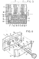
- the end plate 11 is shown in more detail in FIG. 6. It has on its external face a wide hollow band 70 throughout its length. The opposite face of said plate has two shoulders 71 similar to those of the previous plates. Lateral holes 72 centered on said shoulders each open out via an annular bowl 73 on the hollowed-out face 70. A central hole 75 passes through the plate.
- the pads 8b, 8a and 7 of the set J1 for example are threaded through their respective lateral holes 42, 52 and 62 in the fingers 31 of the pad 9 by interposing between said pads the contact blades 5, 4, 3 and the pins 6 as shown in fig. 2, said blades and pins also being inserted in the fingers 31.
- the ends of the fingers 31 are then riveted in the corresponding cups 63 by ultrasound.
- the plates, blades and pins are assembled in sets J1, J2, J3 to form end sets J1, J2 of the stacking block and sets J3 inside said block.
- This pre-assembly of the elements by sets J1, J2, J3, facilitates storage and makes it possible to manufacture relays with number of contacts varying on request, by simple fitting of a combination of said sets, the stacking blocks thus being produced so modular.
- the stacking block detailed in FIGS. 2 and 4 can be fixed to the cylinder head by two different means making it possible to apply distributed pressure to said block.
- a first fixing means consists of a bar 12 (fig. 6) with flexible branches comprising on either side of a rigid central part a straight part 15 and a curved end 16.
- the central part of the plate has a reinforcement annular 17 pierced with a hole 18.
- the bar 12 is disposed in the housing 70 of the end plate 11 and the pins 60 of the end plate 7 are adjusted in the holes 85 of the base 2 (figs 5, 6 and 9) fixed transversely on the relay cylinder head 1.
- Said base has in the center a threaded hole 87 into which is screwed the threaded end of the screw 13 which applies the stacking block against the base by pressing the central part 17 and end parts 16 of the bar.
- the base comprises opposite the frame 88 a recess 89 allowing the free play of said frame.
- Another fastening means consists of a flexible U-shaped flange 90 (FIG. 10), the common branch of which comprises towards the inside of the U a central bulge 91, and two lateral bulges 92, 93.
- the common branch of the flange is placed in the recessed part 70 of the plate of the stacking block.
- the cylinder head does not have a base 2 but two lateral notches 94 receiving the ends 95 of the flange 90 and the pins of the stacking block.
- the bulges of the flange exert a clamping pressure of the pads distributed over the central and lateral zones of said pads.
Landscapes
- Physics & Mathematics (AREA)
- Electromagnetism (AREA)
- Surgical Instruments (AREA)
- Container, Conveyance, Adherence, Positioning, Of Wafer (AREA)
- Connection Of Plates (AREA)
Applications Claiming Priority (2)
| Application Number | Priority Date | Filing Date | Title |
|---|---|---|---|
| FR7915783 | 1979-06-20 | ||
| FR7915783A FR2459545A1 (fr) | 1979-06-20 | 1979-06-20 | Relais electromagnetique |
Publications (2)
| Publication Number | Publication Date |
|---|---|
| EP0021976A1 EP0021976A1 (fr) | 1981-01-07 |
| EP0021976B1 true EP0021976B1 (fr) | 1984-05-30 |
Family
ID=9226850
Family Applications (1)
| Application Number | Title | Priority Date | Filing Date |
|---|---|---|---|
| EP19800400877 Expired EP0021976B1 (fr) | 1979-06-20 | 1980-06-17 | Relais électromagnétique |
Country Status (3)
| Country | Link |
|---|---|
| EP (1) | EP0021976B1 (enExample) |
| DE (1) | DE3068013D1 (enExample) |
| FR (1) | FR2459545A1 (enExample) |
Families Citing this family (2)
| Publication number | Priority date | Publication date | Assignee | Title |
|---|---|---|---|---|
| US4532487A (en) * | 1983-02-28 | 1985-07-30 | Matsushita Electric Works, Ltd. | Relay structure |
| WO2022228751A1 (en) * | 2021-04-30 | 2022-11-03 | Hitachi Energy Switzerland Ag | Electromagnetic relay |
Family Cites Families (8)
| Publication number | Priority date | Publication date | Assignee | Title |
|---|---|---|---|---|
| US2838631A (en) * | 1955-02-01 | 1958-06-10 | Westinghouse Air Brake Co | Electrical relays |
| DE1171086B (de) * | 1960-10-05 | 1964-05-27 | Standard Elektrik Lorenz Ag | Befestigung von Federsaetzen, insbesondere von Relais mit Drahtfedern |
| US3431521A (en) * | 1966-02-24 | 1969-03-04 | Fujitsu Ltd | Electromagnetic relay of small size and simple structure with unitary core and yoke member |
| US3406361A (en) * | 1966-05-11 | 1968-10-15 | Square D Co | Electromagnetic relay having parts retained by a one-piece spring clip which also provides armature bias |
| US3548139A (en) * | 1967-11-07 | 1970-12-15 | Gen Signal Corp | Electromagnetic relay structure |
| ZA701531B (en) * | 1969-03-13 | 1971-04-28 | Davall S & Sons Ltd | Improvements in or relating to electrical relay devices |
| GB1337678A (en) * | 1971-03-03 | 1973-11-21 | Hopwood Developments Ltd F W | Relay units |
| FR2254873A1 (en) * | 1973-12-18 | 1975-07-11 | Gp App Electro Mecaniqu | Electro-magnetic bistable relay - has vibration damping contact blade and permanent magnet locking relay |
-
1979
- 1979-06-20 FR FR7915783A patent/FR2459545A1/fr active Granted
-
1980
- 1980-06-17 DE DE8080400877T patent/DE3068013D1/de not_active Expired
- 1980-06-17 EP EP19800400877 patent/EP0021976B1/fr not_active Expired
Also Published As
| Publication number | Publication date |
|---|---|
| DE3068013D1 (en) | 1984-07-05 |
| FR2459545A1 (fr) | 1981-01-09 |
| EP0021976A1 (fr) | 1981-01-07 |
| FR2459545B1 (enExample) | 1982-05-14 |
Similar Documents
| Publication | Publication Date | Title |
|---|---|---|
| EP0735629B1 (fr) | Agencement de connexion pour fils conducteurs électriques et module, notamment de type bloc de jonction, équipé d'un tel agencement | |
| FR2504316A1 (fr) | Contact electrique | |
| EP0807995B1 (fr) | Dispositif pour raccorder un câble coaxial à une carte de circuit imprimé | |
| FR2685556A1 (fr) | Element modulaire de connexion electrique. | |
| FR2685554A1 (fr) | Element modulaire de connexion electrique. | |
| EP0121467B1 (fr) | Microconnecteur à haute densité de contacts | |
| FR2685555A1 (fr) | Connecteur electrique destine a recevoir un support plat. | |
| FR2669149A1 (fr) | Connecteur intermediaire entre carte de circuit imprime et substrat a circuits electroniques actifs. | |
| EP1520322A1 (fr) | Dispositif de connexion pour circuit souple | |
| EP2912725A1 (fr) | Contact électrique et circuit électronique | |
| FR2566969A1 (fr) | Element de contact electrique d'un connecteur et procede de fabrication de cet element | |
| FR2552940A1 (fr) | Bloc de montage pour interconnecter des connecteurs a une plaque a circuits imprimes | |
| FR2648628A1 (fr) | Systeme de connecteurs electriques | |
| EP0021976B1 (fr) | Relais électromagnétique | |
| FR2541815A1 (fr) | Relais electromagnetique a armature articulee | |
| EP0081795B1 (fr) | Connecteur électrique à couplage multiple et son utilisation dans des connecteurs multiples de mesure pour cartes de circuits d'équipement électronique monté dans un châssis | |
| FR2555805A1 (fr) | Relais electromagnetique a peigne | |
| EP0708462B1 (fr) | Pince de contact éléctrique, et dispositif à pince pourvu d'une telle pince | |
| EP0768727B1 (fr) | Bornier électrique | |
| FR2545283A1 (fr) | Dispositif de contact | |
| EP0080389B1 (fr) | Contact électrique et application à un connecteur | |
| EP0975057B1 (fr) | "Piece de contact pour connecteur femelle, et connecteur comportant une telle piece de contact" | |
| FR2575609A1 (fr) | Borne de connexion pour cables metalliques | |
| EP1374342A1 (fr) | Connecteur pour montage en surface de circuit imprime et procede de fabrication | |
| EP0645938B1 (fr) | Réglette de connexion à coupure intégrée |
Legal Events
| Date | Code | Title | Description |
|---|---|---|---|
| PUAI | Public reference made under article 153(3) epc to a published international application that has entered the european phase |
Free format text: ORIGINAL CODE: 0009012 |
|
| AK | Designated contracting states |
Designated state(s): BE CH DE GB IT NL SE |
|
| 17P | Request for examination filed |
Effective date: 19810611 |
|
| ITF | It: translation for a ep patent filed | ||
| GRAA | (expected) grant |
Free format text: ORIGINAL CODE: 0009210 |
|
| PGFP | Annual fee paid to national office [announced via postgrant information from national office to epo] |
Ref country code: CH Payment date: 19840514 Year of fee payment: 5 |
|
| PGFP | Annual fee paid to national office [announced via postgrant information from national office to epo] |
Ref country code: DE Payment date: 19840529 Year of fee payment: 5 |
|
| AK | Designated contracting states |
Designated state(s): BE CH DE GB IT LI NL SE |
|
| PGFP | Annual fee paid to national office [announced via postgrant information from national office to epo] |
Ref country code: NL Payment date: 19840629 Year of fee payment: 5 |
|
| PGFP | Annual fee paid to national office [announced via postgrant information from national office to epo] |
Ref country code: BE Payment date: 19840630 Year of fee payment: 5 |
|
| REF | Corresponds to: |
Ref document number: 3068013 Country of ref document: DE Date of ref document: 19840705 |
|
| PGFP | Annual fee paid to national office [announced via postgrant information from national office to epo] |
Ref country code: SE Payment date: 19840930 Year of fee payment: 5 |
|
| PLBE | No opposition filed within time limit |
Free format text: ORIGINAL CODE: 0009261 |
|
| STAA | Information on the status of an ep patent application or granted ep patent |
Free format text: STATUS: NO OPPOSITION FILED WITHIN TIME LIMIT |
|
| 26N | No opposition filed | ||
| PG25 | Lapsed in a contracting state [announced via postgrant information from national office to epo] |
Ref country code: SE Effective date: 19850618 |
|
| PG25 | Lapsed in a contracting state [announced via postgrant information from national office to epo] |
Ref country code: LI Effective date: 19850630 Ref country code: CH Effective date: 19850630 Ref country code: BE Effective date: 19850630 |
|
| BERE | Be: lapsed |
Owner name: CIE INDUSTRIELLE DES TELECOMMUNICATIONS CIT-ALCAT Effective date: 19850617 |
|
| PG25 | Lapsed in a contracting state [announced via postgrant information from national office to epo] |
Ref country code: NL Effective date: 19860101 |
|
| GBPC | Gb: european patent ceased through non-payment of renewal fee | ||
| REG | Reference to a national code |
Ref country code: CH Ref legal event code: PL |
|
| PG25 | Lapsed in a contracting state [announced via postgrant information from national office to epo] |
Ref country code: DE Effective date: 19860301 |
|
| NLV4 | Nl: lapsed or anulled due to non-payment of the annual fee | ||
| PG25 | Lapsed in a contracting state [announced via postgrant information from national office to epo] |
Ref country code: GB Effective date: 19881118 |
|
| EUG | Se: european patent has lapsed |
Ref document number: 80400877.9 Effective date: 19860728 |