EP0021976B1 - Electromagnetic relay - Google Patents
Electromagnetic relay Download PDFInfo
- Publication number
- EP0021976B1 EP0021976B1 EP19800400877 EP80400877A EP0021976B1 EP 0021976 B1 EP0021976 B1 EP 0021976B1 EP 19800400877 EP19800400877 EP 19800400877 EP 80400877 A EP80400877 A EP 80400877A EP 0021976 B1 EP0021976 B1 EP 0021976B1
- Authority
- EP
- European Patent Office
- Prior art keywords
- plates
- plate
- support block
- electromagnetic relay
- fixed
- Prior art date
- Legal status (The legal status is an assumption and is not a legal conclusion. Google has not performed a legal analysis and makes no representation as to the accuracy of the status listed.)
- Expired
Links
Images


Classifications
-
- H—ELECTRICITY
- H01—ELECTRIC ELEMENTS
- H01H—ELECTRIC SWITCHES; RELAYS; SELECTORS; EMERGENCY PROTECTIVE DEVICES
- H01H50/00—Details of electromagnetic relays
- H01H50/02—Bases; Casings; Covers
- H01H50/04—Mounting complete relay or separate parts of relay on a base or inside a case
- H01H50/041—Details concerning assembly of relays
-
- H—ELECTRICITY
- H01—ELECTRIC ELEMENTS
- H01H—ELECTRIC SWITCHES; RELAYS; SELECTORS; EMERGENCY PROTECTIVE DEVICES
- H01H50/00—Details of electromagnetic relays
- H01H50/54—Contact arrangements
- H01H50/56—Contact spring sets
-
- H—ELECTRICITY
- H01—ELECTRIC ELEMENTS
- H01H—ELECTRIC SWITCHES; RELAYS; SELECTORS; EMERGENCY PROTECTIVE DEVICES
- H01H1/00—Contacts
- H01H1/12—Contacts characterised by the manner in which co-operating contacts engage
- H01H1/14—Contacts characterised by the manner in which co-operating contacts engage by abutting
- H01H1/24—Contacts characterised by the manner in which co-operating contacts engage by abutting with resilient mounting
- H01H1/26—Contacts characterised by the manner in which co-operating contacts engage by abutting with resilient mounting with spring blade support
- H01H2001/265—Contacts characterised by the manner in which co-operating contacts engage by abutting with resilient mounting with spring blade support having special features for supporting, locating or pre-stressing the contact blade springs
-
- H—ELECTRICITY
- H01—ELECTRIC ELEMENTS
- H01H—ELECTRIC SWITCHES; RELAYS; SELECTORS; EMERGENCY PROTECTIVE DEVICES
- H01H50/00—Details of electromagnetic relays
- H01H50/64—Driving arrangements between movable part of magnetic circuit and contact
- H01H50/641—Driving arrangements between movable part of magnetic circuit and contact intermediate part performing a rectilinear movement
- H01H50/642—Driving arrangements between movable part of magnetic circuit and contact intermediate part performing a rectilinear movement intermediate part being generally a slide plate, e.g. a card
Definitions
- the invention relates to electromagnetic relays of the stacking type of electrical contact blades, in particular for telecommunications.
- the stacking of the contact blades and the plates requires precise alignment so that the facing contacts at the end of said blades can be established on an optimum surface.
- An approximate centering can be obtained by fixing the stack to the cylinder head of the relay by means of two screws or rivets passing through the blade-insert assembly. This has the disadvantage of requiring a large dimensioning of the blades and a certain clearance between the diameter of the screws and the drilling holes.
- a solution for a more precise alignment of blades of a small size consists in using only one fixing screw for a block of two stacks of blades, said blades of each stack being centered by two insulating pins passing through the assembly blade plates in the axis of symmetry of said blades.
- these insulating pins must be calibrated with precision, which weighs significantly on the cost of the product.
- the patent US-A-2838631 describes a different solution in which a single screw makes it possible to fix a block of two stacks of blades, the block consists of insulating plates which can be inserted one inside the other thanks to transverse recesses and complementary shoulders respectively made on either side of the plates to ensure the positioning of the blades inserted between these nested plates.
- the fixing of the stacking block by a screw or a rivet passing through the central part of the block has the drawback of concentrating the pressure on the central zone of the plates, the lateral parts of which tend to spread out in a fan on either side of the central area.
- German patent provides in particular a central crown flange associated with a flat leaf spring applied between the central crown and the plates as well as a central crown flange and side flaps pressing simultaneously on a leaf spring applied to the platelets.
- Another means of producing stacking blocks consists in coating a part of each strip in molten insulating material in order to obtain a strip-plate and in positioning them according to the preceding solution. Another way is to position the blades of one or more stacks in a special mold and fill the mold with molten insulating material.
- the present invention therefore provides an electromagnetic relay with stacks of fixed and movable electrical contact blades held in at least one support block which is fixed to a yoke of the relay by means of a screw and which consists of interlocking insulating plates one inside the other thanks to transverse recesses and complementary shoulders respectively produced on one and / or the other face of the plates to ensure the positioning in alignment of the contact blades clamped in the recesses by the shoulders under the action of the screw.
- the plates of a support block are assembled in at least two sets, nested and aligned, in each of which the plates are assembled together by means of two retaining fingers carried by the one of them placed at one end of the game in question, the support block being secured to a base, transverse to the cylinder head and integral with this cylinder head, by means of a bar with bent ends and with central part reinforced on which rests on the fixing screw passing through said reinforced central part and said plates in their respective central parts to be screwed into said base so that pressure is distributed over the central part and over the lateral parts of the plates.
- the plates of a support block are assembled in at least two interlocked and aligned sets, in each of which the plates are assembled together by means of two retaining fingers carried by t ' one of them placed at one end of the game in question, the support block being secured to the cylinder head, by means of a U-shaped flange shaped so as to have a central bulge and two lateral bulges so as to be ensured a distribution of the pressure on the central part and on the lateral parts of the pads.
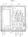
- the relay comprises, integral with the cylinder head 1, a base 2 on which rests a block of stacks of fixed conductive blades 3, 5 and mobile 4 constituting rest-work contacts or RT contacts.
- the conductive strips 3, 4, 5 and their wiring pins 6 are positioned between insulating plates 7, 9, 10, 11 which can be fitted together, some of said plates being extended towards the contact ends of the conductors by an insulating tab 8a, 8b including faces is oblique profile.
- a metal bar 12 fixes the stacking block to the frame of the relay by a screw 13, the end of which is screwed to the base 2.
- the relay is protected by a transparent cover 20 embedded on a base 19.
- the "floating" of the relay in the cover is prohibited in width by the lateral sides of the cylinder head, in length by two pairs of internal ribs 21, 22 with opposite ramps and in height by a shoulder 24 at the bottom of the cover having a bearing on the cylinder head between the bent part of the small face of said cylinder head and the core of the coil.
- Fig. 2 shows the stacking block seen in profile. It includes, for example two columns of two rows of blades 3, 4, 5 or four RT contacts.
- the stacking block is formed by two homologous sets J1 and J2 of contiguous and / or nested elements, each of said sets constituting two RT contacts.
- the J2 set is shown with its elements nested while the J1 set is shown with its spaced elements.
- the row of the pair of working contact blades 5 is sandwiched by interlocking means of the plates 9 and 8b.
- the row of the pair of rest contact blades 3 is sandwiched by interlocking means of plates 8a and 7.
- the intermediate retaining plate 9 or 10 the pallet plates 8a and 8b and the end plate 7 are shown in more detail in FIG. 3.
- the intermediate plate 9 of rectangular shape has on one face two parallel and symmetrical recesses 30 with vertical sides.
- Two retaining fingers 31 molded in the mass of the wafer are each arranged orthogonally to the plane of the wafer; the base of said finger, starting from the bottom of the recess, comprises an annular cup 32.
- the contact blades and the other plates of a stacking set have holes opposite the retaining fingers 31 and are threaded into said fingers .
- the plate 9 has a hole 33 used for the passage of the screw 13 for fixing the stacking block of the contact blades.
- the lateral edges of the plate have, respectively, a recess 34 and a stud 35 located on the face of the plate opposite to that provided with the fingers 31.
- Said recess and stud have a semi-cylindrical shape oriented towards the inside of the disc. so that the stud 35 of the intermediate plate of the set J1 is received in the recess 34 of the intermediate plate of the set J2 and vice versa.
- the face of the wafer on the right profile side 81 of its pallet has two shoulders 40 with a flat base and oblique sides, said bases forming two parallel strips.
- the face of the plate on the oblique profile side 82 has two recesses 41 with straight sides, said recesses being superimposed on the two shoulders 40.
- the plate has two holes 42 each opening on an annular bowl 43, 44 arranged respectively at the top of the shoulder and at the bottom of the recess; said bowls promote the plating of the blades by a suction effect.
- the plate also has a central hole 45.
- the pallet plates 8a and 8b of any play are positioned so that their respective oblique profile faces 83, 82 are facing each other.
- the face of the pallet as an extension of the oblique profile face 83 of the pallet has shoulders 50 with oblique sides.
- the opposite face located on the opposite side with a straight profile 84 of the pallet has recesses 51 with straight sides.
- it has two holes 52 each opening onto a shoulder and a recess via a respective annular bowl 53, 54 and a central hole 55.
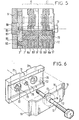
- the end plate 11 is shown in more detail in FIG. 6. It has on its external face a wide hollow band 70 throughout its length. The opposite face of said plate has two shoulders 71 similar to those of the previous plates. Lateral holes 72 centered on said shoulders each open out via an annular bowl 73 on the hollowed-out face 70. A central hole 75 passes through the plate.
- the pads 8b, 8a and 7 of the set J1 for example are threaded through their respective lateral holes 42, 52 and 62 in the fingers 31 of the pad 9 by interposing between said pads the contact blades 5, 4, 3 and the pins 6 as shown in fig. 2, said blades and pins also being inserted in the fingers 31.
- the ends of the fingers 31 are then riveted in the corresponding cups 63 by ultrasound.
- the plates, blades and pins are assembled in sets J1, J2, J3 to form end sets J1, J2 of the stacking block and sets J3 inside said block.
- This pre-assembly of the elements by sets J1, J2, J3, facilitates storage and makes it possible to manufacture relays with number of contacts varying on request, by simple fitting of a combination of said sets, the stacking blocks thus being produced so modular.
- the stacking block detailed in FIGS. 2 and 4 can be fixed to the cylinder head by two different means making it possible to apply distributed pressure to said block.
- a first fixing means consists of a bar 12 (fig. 6) with flexible branches comprising on either side of a rigid central part a straight part 15 and a curved end 16.
- the central part of the plate has a reinforcement annular 17 pierced with a hole 18.
- the bar 12 is disposed in the housing 70 of the end plate 11 and the pins 60 of the end plate 7 are adjusted in the holes 85 of the base 2 (figs 5, 6 and 9) fixed transversely on the relay cylinder head 1.
- Said base has in the center a threaded hole 87 into which is screwed the threaded end of the screw 13 which applies the stacking block against the base by pressing the central part 17 and end parts 16 of the bar.
- the base comprises opposite the frame 88 a recess 89 allowing the free play of said frame.
- Another fastening means consists of a flexible U-shaped flange 90 (FIG. 10), the common branch of which comprises towards the inside of the U a central bulge 91, and two lateral bulges 92, 93.
- the common branch of the flange is placed in the recessed part 70 of the plate of the stacking block.
- the cylinder head does not have a base 2 but two lateral notches 94 receiving the ends 95 of the flange 90 and the pins of the stacking block.
- the bulges of the flange exert a clamping pressure of the pads distributed over the central and lateral zones of said pads.
Landscapes
- Physics & Mathematics (AREA)
- Electromagnetism (AREA)
- Container, Conveyance, Adherence, Positioning, Of Wafer (AREA)
- Surgical Instruments (AREA)
- Connection Of Plates (AREA)
Description
L'invention concerne les relais électromagnétiques du type à empilage de lames de contact électrique notamment pour télécommunications.The invention relates to electromagnetic relays of the stacking type of electrical contact blades, in particular for telecommunications.
Il est connu de réaliser des blocs d'empilages de lames de contact comportant au moins un empilage de lames métalliques séparées par un matériau isolant. Ce matériau peut être constitué de plaquettes obtenues par découpage ou moulage, l'ensemble lames-plaquettes étant fixé à la culasse du refais.It is known to produce blocks for stacking contact blades comprising at least one stack of metal blades separated by an insulating material. This material may consist of plates obtained by cutting or molding, the blade-plate assembly being fixed to the cylinder head of the remake.
L'empilage des lames de contact et des plaquettes nécessite un alignement précis pour que les contacts en regard à l'extrémité desdites lames puissent s'établir sur une surface optimum. Un centrage approximatif peut être obtenu par fixation de l'empilage sur la culasse du relais au moyen de deux vis ou rivets traversant l'ensemble lames-plaquettes. Ceci a pour inconvénient de nécessiter un dimensionnement important des lames et un certain jeu entre le diamètre des vis et des trous de perçage.The stacking of the contact blades and the plates requires precise alignment so that the facing contacts at the end of said blades can be established on an optimum surface. An approximate centering can be obtained by fixing the stack to the cylinder head of the relay by means of two screws or rivets passing through the blade-insert assembly. This has the disadvantage of requiring a large dimensioning of the blades and a certain clearance between the diameter of the screws and the drilling holes.
Une solution pour un alignement plus précis de lames d'un faible encombrement consiste à n'utiliser qu'une seule vis de fixation pour un bloc de deux empilages de lames, lesdites lames de chaque empilage étant centrées par deux broches isolantes traversant l'ensemble plaquettes-lames dans l'axe de symétrie desdites lames. Cependant ces broches isolantes doivent être calibrées avec précision, ce qui pèse de façon sensible sur le coût du produit.A solution for a more precise alignment of blades of a small size consists in using only one fixing screw for a block of two stacks of blades, said blades of each stack being centered by two insulating pins passing through the assembly blade plates in the axis of symmetry of said blades. However, these insulating pins must be calibrated with precision, which weighs significantly on the cost of the product.
Le brevet US-A-2838631 décrit une solution différente dans laquelle une vis unique permet de fixer un bloc de deux empilages de lames, le bloc est constitué de plaquettes isolantes emboîtables les unes dans les autres grâce à des évidements transversaux et des épaulements complémentaires respectivement réalisés sur l'une ou l'autre face des plaquettes pour assurer le positionnement des lames insérées entre ces plaquettes emboîtées.The patent US-A-2838631 describes a different solution in which a single screw makes it possible to fix a block of two stacks of blades, the block consists of insulating plates which can be inserted one inside the other thanks to transverse recesses and complementary shoulders respectively made on either side of the plates to ensure the positioning of the blades inserted between these nested plates.
La fixation du bloc d'empilages par une vis ou un rivet traversant la partie centrale du bloc a pour inconvénient de concentrer la pression sur la zone centrale des plaquettes dont les parties latérales tendent à s'écarter en éventail de part et d'autre de la zone centrale.The fixing of the stacking block by a screw or a rivet passing through the central part of the block has the drawback of concentrating the pressure on the central zone of the plates, the lateral parts of which tend to spread out in a fan on either side of the central area.
Ceci a conduit à l'emploi de brides simples ainsi que montrées dans le brevet GB-A-1 337 678 ou éventuellement plus complexes ainsi que montrées dans le brevet DE-B-171 086 qui visent alors à répartir la pression sur une zone aussi grande que possible. En ce but le brevet allemand prévoit notamment une bride à bombement central associé à un ressort à lame plan appliqué entre le bombement central et les plaquettes ainsi qu'une bride à bombement central et rabats latéraux faisant appui simultanément sur un ressort à lame appliqué sur les plaquettes.This led to the use of simple flanges as shown in patent GB-A-1 337 678 or possibly more complex as shown in patent DE-B-171 086 which then aim to distribute the pressure over an area as great as possible. To this end, the German patent provides in particular a central crown flange associated with a flat leaf spring applied between the central crown and the plates as well as a central crown flange and side flaps pressing simultaneously on a leaf spring applied to the platelets.
Un autre moyen de réalisation de blocs d'empilages consiste à effectuer un enrobage d'une partie de chaque lame dans de la matière isolante en fusion pour obtenir une lame-plaquette et à positionner celles-ci selon la solution précédente. Un autre moyen consiste à positionner dans un moule spécial les lames d'un ou plusieurs empilages et à remplir le moule de matière isolante en fusion.Another means of producing stacking blocks consists in coating a part of each strip in molten insulating material in order to obtain a strip-plate and in positioning them according to the preceding solution. Another way is to position the blades of one or more stacks in a special mold and fill the mold with molten insulating material.
Ces modes de réalisation de blocs d'empilages par enrobage à chaud des lames ont pour inconvénient de provoquer une dégradation de l'élasticité des lames et de créer des tensions internes occasionnant des déréglages des cotes au niveau des contacts.These embodiments of stacking blocks by hot-coating of the blades have the drawback of causing a degradation of the elasticity of the blades and of creating internal tensions causing the dimensions to be adjusted at the level of the contacts.
La présente invention propose donc un relais électromagnétique à empilages de lames de contact électrique fixes et mobiles maintenues dans au moins un bloc-support qui est fixé sur une culasse du relais par l'intermédiaire d'une vis et qui est constitué de plaquettes isolantes emboîtables les unes dans les autres grâce à des évidements transversaux et des épaulements complémentaires respectivement réalisés sur l'une et/ou l'autre face des plaquettes pour assurer le positionnement en alignement des lames de contact serrées dans les évidements par les épaulements sous l'action de la vis.The present invention therefore provides an electromagnetic relay with stacks of fixed and movable electrical contact blades held in at least one support block which is fixed to a yoke of the relay by means of a screw and which consists of interlocking insulating plates one inside the other thanks to transverse recesses and complementary shoulders respectively produced on one and / or the other face of the plates to ensure the positioning in alignment of the contact blades clamped in the recesses by the shoulders under the action of the screw.
Selon une caractéristique de l'invention, les plaquettes d'un bloc-support sont assemblées en au moins deux jeux, emboîtés et alignés, dans chacun desquels les plaquettes sont assemblées entre elles par l'intermédiaire de deux doigts de retenue portés par l'une d'entre elles placée à une extrémité du jeu considéré, le bloc-support étant assujetti à un socle, transversal à la culasse et solidaire de cette culasse, par l'intermédiaire d'une barrette à extrémités infléchies et à partie centrale renforcée sur laquelle prend appui la vis de fixation traversant ladite partie centrale renforcée et lesdites plaquettes dans leurs parties centrales respectives pour se visser dans ledit socle de manière que soit assurée une répartition de la pression sur la partie centrale et sur les parties latérales des plaquettes.According to a characteristic of the invention, the plates of a support block are assembled in at least two sets, nested and aligned, in each of which the plates are assembled together by means of two retaining fingers carried by the one of them placed at one end of the game in question, the support block being secured to a base, transverse to the cylinder head and integral with this cylinder head, by means of a bar with bent ends and with central part reinforced on which rests on the fixing screw passing through said reinforced central part and said plates in their respective central parts to be screwed into said base so that pressure is distributed over the central part and over the lateral parts of the plates.
Selon une autre caractéristique de l'invention, les plaquettes d'un bloc-support sont assemblées en au moins deux jeux emboîtés et alignés, dans chacun desquels les plaquettes sont assemblées entre elles par l'intermédiaire de deux doigts de retenue portés par t'une d'entre elles placée à une extrémité du jeu considéré, le bloc-support étant assujetti à la culasse, par l'intermédiaire d'une bride en U façonnée de manière à présenter un bombement central et deux bombements latéraux de manière que soit assurée une répartition de la pression sur la partie centrale et sur les parties latérales des plaquettes.According to another characteristic of the invention, the plates of a support block are assembled in at least two interlocked and aligned sets, in each of which the plates are assembled together by means of two retaining fingers carried by t ' one of them placed at one end of the game in question, the support block being secured to the cylinder head, by means of a U-shaped flange shaped so as to have a central bulge and two lateral bulges so as to be ensured a distribution of the pressure on the central part and on the lateral parts of the pads.
Les caractéristiques et avantages de l'invention ressortiront de la description d'une forme de réalisation du relais selon t'invention, donnée à titre d'exemple non limitatif, en se reportant aux figures annexées énumérées ci-après:
- - la fig. 1 représente une vue de profil d'un relais selon l'invention dont l'embase et le capot protecteur sont représentés en coupe,
- - la fig. 2 représente en vue de profil un bloc d'empilages de lames conductrices à 2 jeux J1, J2 dont le jeu J1 a ses éléments séparés et le jeu J2 ses éléments emboîtés, - la fig. 3 est une vue en perspective des plaquettes isolantes d'un jeu d'empilages, les plaquettes étant espacées et les lames conductrices non représentées,
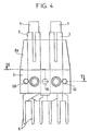
- - la fig. 4 est une vue de profil d'un bloc d'empilages de lames de contact doubles,
- - la fig. 5 représente en coupe un bloc d'empilages de 2 jeux J1, J2 emboîtés et assemblés sur la culasse du relais, les lames de contact n'étant pas représentées,
- - la fig. 6 est une vue en perspective des éléments de fixation de l'empilage sur une plaquette d'extrémité,
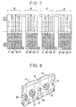
- - la fig. 7 représente en coupe un bloc d'empilages d'un jeu J1, d'un jeu J2 et de 2 jeux intermédiaires J3, les lames de contact n'étant pas représentées,
- - la fig. 8 représente par une vue en perspective une plaquette d'extrémité d'un jeu d'intermédiaire J3,
- - la fig. 9 représente par une vue en perspective la culasse du relais formée d'un socle pour la fixation de l'ensemble barrette-bloc d'empilages,
- - la fig. 10 représente une bride de fixation à niveaux de pression répartie,
- - la fig. 11 représente une vue de dessous du relais embase enlevée, montrant la fixation du bloc d'empilages sur la culasse exempte de socle, au moyen de la bride à niveaux de pression répartie.
- - fig. 1 represents a profile view of a relay according to the invention, the base and the protective cover of which are shown in section,
- - fig. 2 is a side view of a block of stacks of conductive strips with 2 sets J1, J2, the set J1 of which has its separate elements and the set of J2 of its nested elements, - fig. 3 is a perspective view of the insulating plates of a set of stacks, the plates being spaced and the conductive strips not shown,
- - fig. 4 is a side view of a block of stacks of double contact blades,
- - fig. 5 shows in section a stacking block of 2 sets J1, J2 fitted and assembled on the cylinder head of the relay, the contact blades not being shown,
- - fig. 6 is a perspective view of the fastening elements of the stack on an end plate,
- - fig. 7 shows in section a stacking block of a set J1, of a set J2 and of 2 intermediate sets J3, the contact blades not being shown,
- - fig. 8 represents a perspective view of an end plate of an intermediate set J3,
- - fig. 9 is a perspective view of the relay yoke formed by a base for fixing the bar-stacking block assembly,
- - fig. 10 represents a fixing flange with distributed pressure levels,
- - fig. 11 shows a view from below of the base relay removed, showing the fixing of the stacking block to the cylinder head without base, by means of the flange with distributed pressure levels.
Dans la forme de réalisation représentée sur la fig. 1, le relais comporte, solidaire de la culasse 1, un socle 2 sur lequel s'appuie un bloc d'empilages de lames conductrices fixes 3, 5 et mobiles 4 constituant des contacts repos-travail ou contacts RT. Les lames conductrices 3, 4, 5 et leurs broches 6 de câblage sont positionnées entre des plaquettes isolantes 7, 9, 10, 11 emboîtables, certaines desdites plaquettes étant prolongées vers les extrémités de contact des conducteurs par une patte isolante 8a, 8b dont des faces est à profil oblique. Une barrette métallique 12 fixe le bloc d'empilages à l'armature du relais par une vis 13 dont l'extrémité est vissée au socle 2.In the embodiment shown in FIG. 1, the relay comprises, integral with the
Le relais est protégé par un capot 20 transparent encastré sur une embase 19. Le «flottement» du relais dans le capot est interdit en largeur par les côtés latéraux de la culasse, en longueur par deux paires de nervures internes 21, 22 à rampes opposées et en hauteur par un épaulement 24 du fond du capot présentant un appui à la culasse entre la partie coudée de la petite face de ladite culasse et le noyau de la bobine.The relay is protected by a
Les paires de nervures 21, 22 moulées dans la masse du capot respectivement dans la partie médiane du fond du capot et dans une partie latérale adjacente audit fond, permettent d'une part un positionnement correct automatique du relais dans le capot lors de son introduction dans ledit capot et, d'autre part, le calage dudit relais entre la partie coudée de l'armature et un côté de la joue 23 de la bobine.The pairs of
La fig. 2 représente le bloc d'empilages vu de profil. Il comporte, à titre d'exemple deux colonnes de deux rangées de lames 3, 4, 5 soit quatre contacts RT. Le bloc d'empilages est formé de deux jeux homologues J1 et J2 d'éléments accolés et (ou) emboîtés, chacun desdits jeux constituant deux contacts RT. Le jeu J2 est représenté avec ses éléments emboîtés alors que le jeu J1 est représenté avec ses éléments espacés.Fig. 2 shows the stacking block seen in profile. It includes, for example two columns of two rows of
Le jeu J1 comprend:
- - une plaquette intermédiaire 9 comportant des moyens de
retenue 31 des autres plaquettes dudit jeu, - - deux plaquettes à
palettes palettes - - une plaquette d'extrémité 7 prenant appui directement ou non sur la culasse du relais.
- an
intermediate plate 9 comprising means 31 for retaining the other plates of said set, - - Two
pallet plates pallets - - An
end plate 7 bearing directly or indirectly on the cylinder head of the relay.
La rangée de la paire de lames de contact de travail 5 est prise en sandwich par des moyens emboîtables des plaquettes 9 et 8b. La rangée de la paire de lames de contact de repos 3 est prise en sandwich par des moyens emboîtables des plaquettes 8a et 7.The row of the pair of working
Le jeu J2 comprend:
- - une plaquette intermédiaire 10 identique à la 9 du jeu J1 mais retournée de 180° et comportant des doigts de
retenue 31 légèrement plus courts, - - deux plaquettes à
palettes - - une plaquette d'extrémité 11 dont la face externe diffère de celle de son homologue opposée 7 du jeu J1.
- an
intermediate plate 10 identical to the 9 of the set J1 but turned 180 ° and comprising slightly shorter retainingfingers 31, - - two
paddle plates - - An
end plate 11 whose external face differs from that of itsopposite counterpart 7 of the set J1.
La plaquette intermédiaire de retenue 9 ou 10, les plaquettes à palettes 8a et 8b et la plaquette d'extrémité 7 sont représentées avec plus de détails sur la fig. 3. La plaquette intermédiaire 9 de forme rectangulaire comporte sur une face deux évidements parallèles et symétriques 30 à flancs verticaux. Deux doigts de retenue 31 moulés dans la masse de la plaquette sont disposés chacun orthogonalement au plan de la plaquette; la base dudit doigt, partant du fond de l'évidement, comporte une cuvette annulaire 32. Les lames de contact et les autres plaquettes d'un jeu d'empilage comportent des trous en regard des doigts de retenue 31 et sont enfilées dans lesdits doigts. La plaquette 9 comporte un trou 33 servant au passage de la vis 13 de fixation du bloc d'empilages des lames de contact. Les bords latéraux de la plaquette comportent, respectivement un retrait 34 et un téton 35 situés sur la face de la plaquette opposée à celle pourvue des doigts 31. Lesdits retrait et téton ont une forme semi-cylindrique orientée vers l'intérieur de la plaquette de sorte que le téton 35 de la plaquette intermédiaire du jeu J1 vient se loger dans le retrait 34 de la plaquette intermédiaire du jeu J2 et vice versa.The
Les plaquettes à palettes 8b des jeux J1 et J2 sont positionnées de manière que leurs faces à Drofil droit 81 soient en regard. La face de la plaquette côté profil droit 81 de sa palette comporte deux épaulements 40 à base plane et à flancs obliques, lesdites bases formant deux bandes parallèles. La face de la plaquette côté profil oblique 82 comporte deux évidements 41 à flancs droits, lesdits évidements étant superposés aux deux épaulements 40. La plaquette comporte deux trous 42 chacun débouchant sur une cuvette annulaire 43, 44 aménagée respectivement au sommet de l'épaulement et au fond de l'évidement; lesdites cuvettes favorisent le placage des lames par un effet de ventouse. La plaquette comporte également un trou central 45.8b vane platelets games J1 and J2 are positioned so that their right sides to D rofile 81 are opposite. The face of the wafer on the
Les plaquettes à palettes 8a et 8b d'un jeu quelconque sont positionnées de manière que leurs faces respectives à profil oblique 83, 82 soient en regard. La face de la palette en prolongement de la face à profil oblique 83 de la palette comporte des épaulements 50 à flancs obliques. La face opposée située côté face à profil droit 84 de la palette comporte des évidements 51 à flancs droits. Comme la plaquette à palette précédente, celle-ci comporte deux trous 52 débouchant chacun sur un épaulement et un évidement via une cuvette annulaire respective 53, 54 et un trou central 55.The
La plaquette d'extrémité 7 de forme rectangulaire comporte sur une de ses faces deux tétons 60 venant prendre place selon le mode de fixation du bloc d'empilages, dans des trous du socle 2 solidaire de la culasse. La face opposée comporte deux épaulements symétriques 61 à base plane et à flancs obliques, lesdites bases formant deux bandes parallèles et symétriques. La plaquette comporte trois trous en alignement:
- - deux trous latéraux 62, chacun centrés sur
un épaulement 61 et débouchant via une cuvette annulaire 63, sur la face de la plaquette comportant les tétons 60, - - un trou central 65,
- - la fig. 4 est une vue de profil de l'empilage montrant la plaquette d'extrémité 7, deux lames fixes
de contact 3 et deux lames mobiles de contact 4, une plaquette àpalette 8a et les broches 6, - - la fig. 5 montre le bloc d'empilages J1, J2 serré par la vis 13 sur le socle 2.
- two
lateral holes 62, each centered on ashoulder 61 and opening out via anannular bowl 63, on the face of the plate comprising thepins 60, - - a
central hole 65, - - fig. 4 is a profile view of the stack showing the
end plate 7, two fixedcontact blades 3 and two movable contact blades 4, apallet plate 8a and the pins 6, - - fig. 5 shows the stacking block J1, J2 tightened by the
screw 13 on the base 2.
La plaquette d'extrémité 11 est représentée avec plus de détails par la fig. 6. Elle comporte sur sa face externe une large bande évidée 70 dans toute sa longueur. La face opposée de ladite plaquette comporte deux épaulements 71 analogues à ceux des plaquettes précédentes. Des trous latéraux 72 centrés sur lesdits épaulements débouchent chacun via une cuvette annulaire 73 sur la face évidée 70. Un trou central 75 traverse la plaquette.The
Les plaquettes 8b, 8a et 7 du jeu J1 par exemple sont enfilées par leurs trous respectifs latéraux 42, 52 et 62 dans les doigts 31 de la plaquette 9 en intercalant entre lesdites plaquettes les lames de contact 5, 4, 3 et les broches 6 comme indiqué par la fig. 2, lesdites lames et broches étant également embrochées dans les doigts 31. Les extrémités des doigts 31 sont ensuite rivées dans les cuvettes correspondantes 63 par ultrasons.The
Lorsque le bloc d'empilages est constitué par un nombre de jeux supérieur à deux, il comporte un ou plusieurs jeux J3 intercalé(s) entre les jeux J1 et J2. Un jeu J3 comporte (fig. 7):
- - une plaquette intermédiaire 10 identique à la 9 du jeu
J1 ou 10 du jeu J2, - - deux plaquettes à
palette - - une plaquette terminale 14 (fig. 8) comportant les épaulements (71), les trous (72, 75) et les cuvettes (73) de la plaquette 11 (fig. 6) mais la face opposée aux épaulements est plane et dépourvue de
gorge 70, les cuvettes débouchant directement sur ladite face, laquelle comporte en outre un retrait 34et un téton 35 identiques à ceux (34, 35) de la plaquette 9.
- - an
intermediate plate 10 identical to 9 of set J1 or 10 of set J2, - - two
pallet plates - - a terminal plate 14 (fig. 8) comprising the shoulders (71), the holes (72, 75) and the bowls (73) of the plate 11 (fig. 6) but the face opposite to the shoulders is flat and devoid of
groove 70, the bowls opening directly onto said face, which further comprises arecess 34 and astud 35 identical to those (34, 35) of theplate 9.
Les plaquettes, lames et broches sont assemblées en jeux J1, J2, J3 pour constituer des jeux d'extrémité J1, J2 du bloc d'empilages et des jeux J3 intérieurs audit bloc. Ce préassemblage des éléments par jeux J1, J2, J3, facilite le stockage et permet de fabriquer des relais à nombre de contacts variant à la demande, par simple emboîtage d'une combinaison desdits jeux, les blocs d'empilages étant ainsi réalisés de façon modulaire.The plates, blades and pins are assembled in sets J1, J2, J3 to form end sets J1, J2 of the stacking block and sets J3 inside said block. This pre-assembly of the elements by sets J1, J2, J3, facilitates storage and makes it possible to manufacture relays with number of contacts varying on request, by simple fitting of a combination of said sets, the stacking blocks thus being produced so modular.
Le bloc d'empilages détaillé aux figs 2 et 4 peut être fixé à la culasse par deux moyens différents permettant d'effectuer une pression répartie sur ledit bloc.The stacking block detailed in FIGS. 2 and 4 can be fixed to the cylinder head by two different means making it possible to apply distributed pressure to said block.
Un premier moyen de fixation consiste en une barrette 12 (fig. 6) à branches flexibles comprenant de part et d'autre d'une partie centrale rigide une partie droite 15 et une extrémité courbe 16. La partie centrale de la plaquette présente un renforcement annulaire 17 percé d'un trou 18. La barrette 12 est disposée dans le logement 70 de la plaquette extrême 11 et les tétons 60 de la plaquette extrême 7 sont ajustés dans les trous 85 du socle 2 (figs 5, 6 et 9) fixé transversalement sur la culasse 1 du relais. Ledit socle comporte au centre un trou fileté 87 dans lequel est vissée l'extrémité filetée de la vis 13 qui applique le bloc d'empilages contre le socle par pression de la partie centrale 17 et des parties extrêmes 16 de la barrette. Le socle comporte en regard de l'armature 88 un évidement 89 permettant le libre jeu de ladite armature.A first fixing means consists of a bar 12 (fig. 6) with flexible branches comprising on either side of a rigid central part a straight part 15 and a
Un autre moyen de fixation consiste en une bride 90 en U flexible (fig. 10) dont la branche commune comporte vers l'intérieur du U un bombement central 91, et deux bombements latéraux 92,93. La branche commune de la bride est placée dans la partie évidée 70 de la plaquette du bloc d'empilages. Dans ce mode de fixation (fig. 11) la culasse ne comporte pas de socle 2 mais deux échancrures latérales 94 recevant les extrémités 95 de la bride 90 et les tétons du bloc d'empilages. Les bombements de la bride exercent une pression de serrage des plaquettes répartie sur les zones centrale et latérale desdites plaquettes.Another fastening means consists of a flexible U-shaped flange 90 (FIG. 10), the common branch of which comprises towards the inside of the U a
Claims (6)
Applications Claiming Priority (2)
| Application Number | Priority Date | Filing Date | Title |
|---|---|---|---|
| FR7915783A FR2459545A1 (en) | 1979-06-20 | 1979-06-20 | ELECTROMAGNETIC RELAY |
| FR7915783 | 1979-06-20 |
Publications (2)
| Publication Number | Publication Date |
|---|---|
| EP0021976A1 EP0021976A1 (en) | 1981-01-07 |
| EP0021976B1 true EP0021976B1 (en) | 1984-05-30 |
Family
ID=9226850
Family Applications (1)
| Application Number | Title | Priority Date | Filing Date |
|---|---|---|---|
| EP19800400877 Expired EP0021976B1 (en) | 1979-06-20 | 1980-06-17 | Electromagnetic relay |
Country Status (3)
| Country | Link |
|---|---|
| EP (1) | EP0021976B1 (en) |
| DE (1) | DE3068013D1 (en) |
| FR (1) | FR2459545A1 (en) |
Families Citing this family (2)
| Publication number | Priority date | Publication date | Assignee | Title |
|---|---|---|---|---|
| CA1209184A (en) * | 1983-02-28 | 1986-08-05 | Mitsuki Nagamoto | Electromagnetic relay structure |
| WO2022228751A1 (en) * | 2021-04-30 | 2022-11-03 | Hitachi Energy Switzerland Ag | Electromagnetic relay |
Family Cites Families (8)
| Publication number | Priority date | Publication date | Assignee | Title |
|---|---|---|---|---|
| US2838631A (en) * | 1955-02-01 | 1958-06-10 | Westinghouse Air Brake Co | Electrical relays |
| DE1171086B (en) * | 1960-10-05 | 1964-05-27 | Standard Elektrik Lorenz Ag | Fastening of sets of springs, in particular relays with wire springs |
| US3431521A (en) * | 1966-02-24 | 1969-03-04 | Fujitsu Ltd | Electromagnetic relay of small size and simple structure with unitary core and yoke member |
| US3406361A (en) * | 1966-05-11 | 1968-10-15 | Square D Co | Electromagnetic relay having parts retained by a one-piece spring clip which also provides armature bias |
| US3548139A (en) * | 1967-11-07 | 1970-12-15 | Gen Signal Corp | Electromagnetic relay structure |
| ZA701531B (en) * | 1969-03-13 | 1971-04-28 | Davall S & Sons Ltd | Improvements in or relating to electrical relay devices |
| GB1337678A (en) * | 1971-03-03 | 1973-11-21 | Hopwood Developments Ltd F W | Relay units |
| FR2254873A1 (en) * | 1973-12-18 | 1975-07-11 | Gp App Electro Mecaniqu | Electro-magnetic bistable relay - has vibration damping contact blade and permanent magnet locking relay |
-
1979
- 1979-06-20 FR FR7915783A patent/FR2459545A1/en active Granted
-
1980
- 1980-06-17 DE DE8080400877T patent/DE3068013D1/en not_active Expired
- 1980-06-17 EP EP19800400877 patent/EP0021976B1/en not_active Expired
Also Published As
| Publication number | Publication date |
|---|---|
| EP0021976A1 (en) | 1981-01-07 |
| DE3068013D1 (en) | 1984-07-05 |
| FR2459545B1 (en) | 1982-05-14 |
| FR2459545A1 (en) | 1981-01-09 |
Similar Documents
| Publication | Publication Date | Title |
|---|---|---|
| EP0735629B1 (en) | Arrangement for the connection of electrical wire conductors and especially connection module equipped with such an arrangement | |
| FR2504316A1 (en) | ELECTRIC CONTACT | |
| EP0807995B1 (en) | Device for connecting a coaxial cable to a printed circuit board | |
| FR2685556A1 (en) | MODULAR ELEMENT FOR ELECTRICAL CONNECTION. | |
| FR2685554A1 (en) | MODULAR ELEMENT FOR ELECTRICAL CONNECTION. | |
| FR2685555A1 (en) | ELECTRICAL CONNECTOR FOR RECEIVING A FLAT SUPPORT. | |
| FR2669149A1 (en) | Intermediate connector between a printed circuit card and a substrate with active electronic circuits | |
| WO2014064356A1 (en) | Electrical contact and electronic circuit | |
| WO2004001906A1 (en) | Connection device for flexible circuit | |
| FR2566969A1 (en) | ELECTRIC CONTACT ELEMENT OF A CONNECTOR AND METHOD FOR MANUFACTURING THE SAME | |
| FR2552940A1 (en) | MOUNTING BLOCK FOR INTERCONNECTING CONNECTORS TO A PRINTED CIRCUIT BOARD | |
| EP0021976B1 (en) | Electromagnetic relay | |
| FR2648628A1 (en) | ELECTRICAL CONNECTOR SYSTEM | |
| FR2541815A1 (en) | ELECTROMAGNETIC RELAY WITH ARTICULATED FRAME | |
| EP0708462B1 (en) | Electric contacting clamp and clamping device with such a gripping member | |
| FR2555805A1 (en) | ELECTROMAGNETIC COMB RELAY | |
| EP0768727B1 (en) | Electrical terminal block | |
| FR2545283A1 (en) | CONTACT DEVICE | |
| EP0080389A1 (en) | Electrical contact and application to a connector | |
| EP1374342A1 (en) | Connector for printed circuit surface mounting and method for making same | |
| EP0645938B1 (en) | Terminal block with integrated disconnection | |
| CH661831A5 (en) | BASE FOR ELECTRONIC COMPONENT. | |
| EP0975057A1 (en) | Contact piece for female connector and connector comprising such a contact piece | |
| EP1255327A1 (en) | Coaxial electrical connector element | |
| EP0627792A1 (en) | Connector for joining printed circuit boards |
Legal Events
| Date | Code | Title | Description |
|---|---|---|---|
| PUAI | Public reference made under article 153(3) epc to a published international application that has entered the european phase |
Free format text: ORIGINAL CODE: 0009012 |
|
| AK | Designated contracting states |
Designated state(s): BE CH DE GB IT NL SE |
|
| 17P | Request for examination filed |
Effective date: 19810611 |
|
| ITF | It: translation for a ep patent filed |
Owner name: JACOBACCI & PERANI S.P.A. |
|
| GRAA | (expected) grant |
Free format text: ORIGINAL CODE: 0009210 |
|
| PGFP | Annual fee paid to national office [announced via postgrant information from national office to epo] |
Ref country code: CH Payment date: 19840514 Year of fee payment: 5 |
|
| PGFP | Annual fee paid to national office [announced via postgrant information from national office to epo] |
Ref country code: DE Payment date: 19840529 Year of fee payment: 5 |
|
| AK | Designated contracting states |
Designated state(s): BE CH DE GB IT LI NL SE |
|
| PGFP | Annual fee paid to national office [announced via postgrant information from national office to epo] |
Ref country code: NL Payment date: 19840629 Year of fee payment: 5 |
|
| PGFP | Annual fee paid to national office [announced via postgrant information from national office to epo] |
Ref country code: BE Payment date: 19840630 Year of fee payment: 5 |
|
| REF | Corresponds to: |
Ref document number: 3068013 Country of ref document: DE Date of ref document: 19840705 |
|
| PGFP | Annual fee paid to national office [announced via postgrant information from national office to epo] |
Ref country code: SE Payment date: 19840930 Year of fee payment: 5 |
|
| PLBE | No opposition filed within time limit |
Free format text: ORIGINAL CODE: 0009261 |
|
| STAA | Information on the status of an ep patent application or granted ep patent |
Free format text: STATUS: NO OPPOSITION FILED WITHIN TIME LIMIT |
|
| 26N | No opposition filed | ||
| PG25 | Lapsed in a contracting state [announced via postgrant information from national office to epo] |
Ref country code: SE Effective date: 19850618 |
|
| PG25 | Lapsed in a contracting state [announced via postgrant information from national office to epo] |
Ref country code: LI Effective date: 19850630 Ref country code: CH Effective date: 19850630 Ref country code: BE Effective date: 19850630 |
|
| BERE | Be: lapsed |
Owner name: CIE INDUSTRIELLE DES TELECOMMUNICATIONS CIT-ALCAT Effective date: 19850617 |
|
| PG25 | Lapsed in a contracting state [announced via postgrant information from national office to epo] |
Ref country code: NL Effective date: 19860101 |
|
| GBPC | Gb: european patent ceased through non-payment of renewal fee | ||
| REG | Reference to a national code |
Ref country code: CH Ref legal event code: PL |
|
| PG25 | Lapsed in a contracting state [announced via postgrant information from national office to epo] |
Ref country code: DE Effective date: 19860301 |
|
| NLV4 | Nl: lapsed or anulled due to non-payment of the annual fee | ||
| PG25 | Lapsed in a contracting state [announced via postgrant information from national office to epo] |
Ref country code: GB Effective date: 19881118 |
|
| EUG | Se: european patent has lapsed |
Ref document number: 80400877.9 Effective date: 19860728 |