EP0021741B1 - A method and apparatus for coating substrates - Google Patents
A method and apparatus for coating substrates Download PDFInfo
- Publication number
- EP0021741B1 EP0021741B1 EP80301989A EP80301989A EP0021741B1 EP 0021741 B1 EP0021741 B1 EP 0021741B1 EP 80301989 A EP80301989 A EP 80301989A EP 80301989 A EP80301989 A EP 80301989A EP 0021741 B1 EP0021741 B1 EP 0021741B1
- Authority
- EP
- European Patent Office
- Prior art keywords
- coating
- hopper
- planar
- substrate
- liquid
- Prior art date
- Legal status (The legal status is an assumption and is not a legal conclusion. Google has not performed a legal analysis and makes no representation as to the accuracy of the status listed.)
- Expired
Links
- 238000000576 coating method Methods 0.000 title claims description 122
- 239000011248 coating agent Substances 0.000 title claims description 121
- 239000000758 substrate Substances 0.000 title claims description 51
- 238000000034 method Methods 0.000 title claims description 19
- 239000011324 bead Substances 0.000 claims description 57
- 239000007788 liquid Substances 0.000 claims description 45
- 238000011144 upstream manufacturing Methods 0.000 claims description 10
- 239000010410 layer Substances 0.000 description 19
- 230000007547 defect Effects 0.000 description 17
- 239000002131 composite material Substances 0.000 description 8
- 238000005516 engineering process Methods 0.000 description 5
- 238000001125 extrusion Methods 0.000 description 5
- 239000000463 material Substances 0.000 description 5
- 229910052709 silver Inorganic materials 0.000 description 4
- 239000004332 silver Substances 0.000 description 4
- 230000000694 effects Effects 0.000 description 3
- 239000002245 particle Substances 0.000 description 3
- -1 silver halide Chemical class 0.000 description 3
- XLYOFNOQVPJJNP-UHFFFAOYSA-N water Substances O XLYOFNOQVPJJNP-UHFFFAOYSA-N 0.000 description 3
- GWEVSGVZZGPLCZ-UHFFFAOYSA-N Titan oxide Chemical compound O=[Ti]=O GWEVSGVZZGPLCZ-UHFFFAOYSA-N 0.000 description 2
- XLOMVQKBTHCTTD-UHFFFAOYSA-N Zinc monoxide Chemical compound [Zn]=O XLOMVQKBTHCTTD-UHFFFAOYSA-N 0.000 description 2
- 239000011247 coating layer Substances 0.000 description 2
- 239000000428 dust Substances 0.000 description 2
- 239000000839 emulsion Substances 0.000 description 2
- 238000004519 manufacturing process Methods 0.000 description 2
- 230000002265 prevention Effects 0.000 description 2
- 239000002356 single layer Substances 0.000 description 2
- 239000000126 substance Substances 0.000 description 2
- 229920003002 synthetic resin Polymers 0.000 description 2
- 239000000057 synthetic resin Substances 0.000 description 2
- 108010010803 Gelatin Proteins 0.000 description 1
- BQCADISMDOOEFD-UHFFFAOYSA-N Silver Chemical compound [Ag] BQCADISMDOOEFD-UHFFFAOYSA-N 0.000 description 1
- 238000009825 accumulation Methods 0.000 description 1
- 230000001154 acute effect Effects 0.000 description 1
- 239000000654 additive Substances 0.000 description 1
- 239000011230 binding agent Substances 0.000 description 1
- 238000007796 conventional method Methods 0.000 description 1
- 230000006378 damage Effects 0.000 description 1
- 239000012954 diazonium Substances 0.000 description 1
- 150000001989 diazonium salts Chemical class 0.000 description 1
- 238000009501 film coating Methods 0.000 description 1
- 229920000159 gelatin Polymers 0.000 description 1
- 239000008273 gelatin Substances 0.000 description 1
- 235000019322 gelatine Nutrition 0.000 description 1
- 235000011852 gelatine desserts Nutrition 0.000 description 1
- 239000011229 interlayer Substances 0.000 description 1
- 230000001788 irregular Effects 0.000 description 1
- 229910052751 metal Inorganic materials 0.000 description 1
- 239000002184 metal Substances 0.000 description 1
- 239000011241 protective layer Substances 0.000 description 1
- 238000007790 scraping Methods 0.000 description 1
- 238000004062 sedimentation Methods 0.000 description 1
- 230000001235 sensitizing effect Effects 0.000 description 1
- 238000005507 spraying Methods 0.000 description 1
- 239000010409 thin film Substances 0.000 description 1
- 239000004408 titanium dioxide Substances 0.000 description 1
- 239000011787 zinc oxide Substances 0.000 description 1
Images

Classifications
-
- G—PHYSICS
- G03—PHOTOGRAPHY; CINEMATOGRAPHY; ANALOGOUS TECHNIQUES USING WAVES OTHER THAN OPTICAL WAVES; ELECTROGRAPHY; HOLOGRAPHY
- G03C—PHOTOSENSITIVE MATERIALS FOR PHOTOGRAPHIC PURPOSES; PHOTOGRAPHIC PROCESSES, e.g. CINE, X-RAY, COLOUR, STEREO-PHOTOGRAPHIC PROCESSES; AUXILIARY PROCESSES IN PHOTOGRAPHY
- G03C1/00—Photosensitive materials
- G03C1/74—Applying photosensitive compositions to the base; Drying processes therefor
-
- B—PERFORMING OPERATIONS; TRANSPORTING
- B05—SPRAYING OR ATOMISING IN GENERAL; APPLYING FLUENT MATERIALS TO SURFACES, IN GENERAL
- B05C—APPARATUS FOR APPLYING FLUENT MATERIALS TO SURFACES, IN GENERAL
- B05C5/00—Apparatus in which liquid or other fluent material is projected, poured or allowed to flow on to the surface of the work
- B05C5/007—Slide-hopper coaters, i.e. apparatus in which the liquid or other fluent material flows freely on an inclined surface before contacting the work
-
- B—PERFORMING OPERATIONS; TRANSPORTING
- B05—SPRAYING OR ATOMISING IN GENERAL; APPLYING FLUENT MATERIALS TO SURFACES, IN GENERAL
- B05C—APPARATUS FOR APPLYING FLUENT MATERIALS TO SURFACES, IN GENERAL
- B05C5/00—Apparatus in which liquid or other fluent material is projected, poured or allowed to flow on to the surface of the work
- B05C5/02—Apparatus in which liquid or other fluent material is projected, poured or allowed to flow on to the surface of the work the liquid or other fluent material being discharged through an outlet orifice by pressure, e.g. from an outlet device in contact or almost in contact, with the work
- B05C5/0254—Coating heads with slot-shaped outlet
-
- B—PERFORMING OPERATIONS; TRANSPORTING
- B05—SPRAYING OR ATOMISING IN GENERAL; APPLYING FLUENT MATERIALS TO SURFACES, IN GENERAL
- B05C—APPARATUS FOR APPLYING FLUENT MATERIALS TO SURFACES, IN GENERAL
- B05C9/00—Apparatus or plant for applying liquid or other fluent material to surfaces by means not covered by any preceding group, or in which the means of applying the liquid or other fluent material is not important
- B05C9/06—Apparatus or plant for applying liquid or other fluent material to surfaces by means not covered by any preceding group, or in which the means of applying the liquid or other fluent material is not important for applying two different liquids or other fluent materials, or the same liquid or other fluent material twice, to the same side of the work
-
- G—PHYSICS
- G03—PHOTOGRAPHY; CINEMATOGRAPHY; ANALOGOUS TECHNIQUES USING WAVES OTHER THAN OPTICAL WAVES; ELECTROGRAPHY; HOLOGRAPHY
- G03C—PHOTOSENSITIVE MATERIALS FOR PHOTOGRAPHIC PURPOSES; PHOTOGRAPHIC PROCESSES, e.g. CINE, X-RAY, COLOUR, STEREO-PHOTOGRAPHIC PROCESSES; AUXILIARY PROCESSES IN PHOTOGRAPHY
- G03C1/00—Photosensitive materials
- G03C1/74—Applying photosensitive compositions to the base; Drying processes therefor
- G03C2001/7411—Beads or bead coating
-
- G—PHYSICS
- G03—PHOTOGRAPHY; CINEMATOGRAPHY; ANALOGOUS TECHNIQUES USING WAVES OTHER THAN OPTICAL WAVES; ELECTROGRAPHY; HOLOGRAPHY
- G03C—PHOTOSENSITIVE MATERIALS FOR PHOTOGRAPHIC PURPOSES; PHOTOGRAPHIC PROCESSES, e.g. CINE, X-RAY, COLOUR, STEREO-PHOTOGRAPHIC PROCESSES; AUXILIARY PROCESSES IN PHOTOGRAPHY
- G03C1/00—Photosensitive materials
- G03C1/74—Applying photosensitive compositions to the base; Drying processes therefor
- G03C2001/7466—Geometry and shape of application devices
-
- G—PHYSICS
- G03—PHOTOGRAPHY; CINEMATOGRAPHY; ANALOGOUS TECHNIQUES USING WAVES OTHER THAN OPTICAL WAVES; ELECTROGRAPHY; HOLOGRAPHY
- G03C—PHOTOSENSITIVE MATERIALS FOR PHOTOGRAPHIC PURPOSES; PHOTOGRAPHIC PROCESSES, e.g. CINE, X-RAY, COLOUR, STEREO-PHOTOGRAPHIC PROCESSES; AUXILIARY PROCESSES IN PHOTOGRAPHY
- G03C1/00—Photosensitive materials
- G03C1/74—Applying photosensitive compositions to the base; Drying processes therefor
- G03C2001/7477—Lip detail or shape in hopper or extrusion head
Definitions
- the present invention relates to an improvement in coating methods and apparatus.
- the invention is particularly useful for coating one or more layers of coating liquid onto a substrate such as a support for a photosensitive material with a hopper such as a slide hopper or an extrusion hopper.
- a method for coating one or more layers onto a substrate, a method is known in which a coating liquid supplied from a slide hopper or extrusion hopper forms a coating bead bridging the hopper and a moving substrate and a part of the bead is formed on the side of the hopper where the substrate enters, as described in the U.S. Patent 2,761,419 and U.S. Patent 2,761,791.
- An object of the present invention is to reduce or prevent the occurrence of streak defects caused either at the start of coating, or when passing joint portions are being coated or when foreign matter sticks to the substrate.
- a further object is to reduce the occurrence of streak defects without apsecial treatment to the joint portions of the substrate.
- the coating liquid supplied from the hopper forms a bead, a part of which is formed at the side which the substrate enters with respect to an efflux end of the supplied coating liquid in the upstream side.
- the end of the coating bead formed at the side is in contact with a part of hopper (which is called hereinafter "coating surface").
- the end of the coating bead can easily be held at the fixed position by being in contact with a liquid-end-holding portion arranged on the coating surface.
- a hopper is shown generally at 1, 2 represents an efflux surface for a coating liquid, 3 represents a substrate to be coated mounted on a roller 11, 4 represents a coating surface of the hopper and 5 represents a bead.
- the end portion 5' of bead 5 is in contact with the substrate to be coated 3 and coating surface 4; if bead 5 suffers disturbance or disorder, it is believed that the ending portion of bead 5 moves back and forth to, say, positions 5" or 5"'; this movement conceptually includes a vertical motion and is a back-and-forth motion when viewed from the entering side of the substrate.
- the present invention is based upon the above described observations, and is accomplished such that if the disturbance and disorder of the beads are small, they may be absorbed at the end of the beads, and even if they are almost destroyed the end of the beads can immediately be restored to its original state.
- improvement [4] which may be regarded as a very useful coating technology from the point of view of streak defect prevention, it is difficult to hold the end of the bead at a fixed place or to restore the said end to its original state.
- GS-A-3749053 discloses a coating apparatus which, to overcome the problems of cavitation and thus facilitate the flow of the coating liquid onto the substrate, is provided with a small cavity or reservoir in the coating surface. This cavity or reservoir is thus to ensure that sufficient coating liquid is supplied to the coating surface and not to overcome streak defects caused by the bead and is for an entirely different purpose.
- Figures 5 and 6 of this disclosure illustrate embodiments where the efflux end is provided with a slanted surface or a concave surface on the upstream side.
- a second layer is applied simultaneously over the layer resulting from the liquid issuing from the cavity.
- FIGS 2 to 6 illustrate examples of apparatus for use in the method of the invention.
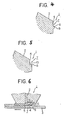
- a coating liquid puddle or sump 7 having a liquid-end-holding portion 6 is provided; the said portion 6 holds the end of the head 5 in contact with the coating surface 4 of the hopper i.e. the hopper coating surface is provided with coating liquid accumulation means.
- the liquid end holding portion 6 of the invention may be the one that can hold the contacting end of the bead 5; as can be seen in Figures 2 to 6, a right angled or slightly acute or obtuse angled point is formed on the coating surface 4 of the hopper by notching or scraping the said surface 4; the said point forms the end of the "puddle” means 7.
- the angle of the point that serves as the liquid end holding portion 6 can be varied depending on the viscosity and surface tension, etc. of the coating solution; the angle can be arranged so that the contact end of the beads is held at a contact angle as wide as possible. Generally a right angle is preferred.
- the coating surface 4 of the hopper is notched or scraped off at right angles up to a certain area in Figure 2.
- the coating surface 4 is notched or scraped off at right angles and, further, the end of the notch remote from the efflux point is further notched or scraped off, to provide recess 8, as shown in Figure 3.
- a protrusion 9 can be formed on the coating surface 4, such that a puddle or reserve 7 having a liquid-end-holding portion 6 is formed, as shown in Figure 4.
- the cut-away portion may possess a rounded portion 10 as shown in Figure 5.
- the present invention is applicable not only to single layer type or multi-layer type slide-hoppers ( Figures 1 and 2 do, in effect, illustrate 2-layer slide hoppers), but also to single-layer or multi-layer type extrusion hoppers, for example.
- a typical extrusion hopper for use in the present invention is shown in Figure 6, where the reference numerals are the same as used for Figures 1 to 5.
- the distance from the coating liquid efflux end to the position where the liquid end holding portion 6 is formed, that is the length of the liquid reserve or puddle 7 (the length, a, in Figures 2 and 6) is generally 20-1,000 pm, preferably 200-700 um, and the depth of the puddle 7, that is, the distance from the interior of the puddle 7 to the liquid-end-holding portion 6 (the length, b, in Figures 2 and 6) is generally 10-600 pm, preferably 30-100 um.
- these dimensions a and b depend upon the viscosity and surface tension of the coating liquid, the nature of the substrate 3 or the positioning of the hopper 1 to the substrate 3 or roller 11 which conveys the substrate.
- the coating liquid to be used in the invention is generally a water-soluble coating composite, but an organic or other inorganic liquid medium can also be used.
- an organic or other inorganic liquid medium can also be used.
- the present invention is particularly effective for manufacture of photographic material but can also be applied to many other fields of coating or covering such as in the manufacture of an inorganic coating paper that requires one or more coating layers, with separate coating layers being one or more different composites, for the purpose of giving a special effect to the products.
- the coating composites for photographic use include the liquid coating composites which form not only a silver halide emulsion layer and other photographic light-sensitive layer but also a non- light-sensitive layer such as a subbing layer, interlayer or protective layer.
- the viscosity of such coating composite for photographic use is generally approx. 2 x 10- 3 to 150 x 10- 3 ' Pa.s (2 x 150 cp), but more particularly 5 x 10- 3 to 100 x 10- 3 Pa.s (5 to 100 cp). They generally possess a surface tension of 14 x 10- 4 to 50 x 10- 4 N (14 to 50 dynes).
- the substrate to be coated by the method of the present invention may be, for example, a synthetic resin sheet, a paper or a metal; these are well known as the supports for photographic use but the supports may be used for uses other than photographic.
- This substrate may also have one or more layers which are in a substantially dry state.
- the coating liquid to be used in the invention may contain photosensitive materials such as silver halide, zinc oxide, titanium dioxide, diazonium salt and sensitizing dye, as well as one or two or more materials used as additives for photographic use.
- a coating composite containing gelatin as binder was coated over a synthetic resin support (substrate) at a multiple layer coating speed (CS) of 50 m/min. It was found that the streak defect was checked completely or was minimal as compared with the results obtained from the usual methods but using the same coating conditions, that is, the results obtained using a hopper as shown in Figure 1. Further satisfactory coating matter could be obtained even when applying a faster coating speed than usual. The capability of a usual type of hopper was not affected.
- the contact portion of the bead to the coating surface of the hopper does not move as it is held in contact with the liquid end holding portion, since the end of the said bead is held in contact with the liquid end holding portion of the coating liquid puddle or sump which forms on the coating surface of the hopper. Further the end contact portion of the bead on the side of the said liquid end holding portion pulls back the movement of the contact portion of the said beads to the substrate and then restores it to the original stage.
- the end of the bead will immediately revert to the said liquid end holding portion, thus restoring it to its original state and put in uniform order. Therefore, in the present invention, the end of the bead can be restored to its original state, i.e. the state of regular coating, thus providing uniform coating. In this way the occurrence of streak defect can be . kept to a minimum, even if the beads should be disturbed or disordered or even should the beads be destroyed, not to mention the regular coating state.
Landscapes
- Chemical & Material Sciences (AREA)
- Engineering & Computer Science (AREA)
- Materials Engineering (AREA)
- Physics & Mathematics (AREA)
- General Physics & Mathematics (AREA)
- Application Of Or Painting With Fluid Materials (AREA)
- Coating Apparatus (AREA)
Description
- The present invention relates to an improvement in coating methods and apparatus. The invention is particularly useful for coating one or more layers of coating liquid onto a substrate such as a support for a photosensitive material with a hopper such as a slide hopper or an extrusion hopper.
- So far, for coating one or more layers onto a substrate, a method is known in which a coating liquid supplied from a slide hopper or extrusion hopper forms a coating bead bridging the hopper and a moving substrate and a part of the bead is formed on the side of the hopper where the substrate enters, as described in the U.S. Patent 2,761,419 and U.S. Patent 2,761,791.
- With these conventional methods, however, various defects appear on the coated layer formed on the substrate if the said beads receive a disturbance or disorder. The defect that draws special attention, is the occurrence of a streak defect in which a longitudinal streak appears; this streak defect may cause serious results resulting in scrapping products in coating the photosensitive material. Some of these streak defects occur after coating has started and others occur as a joint in the substrate to be coated is being coated or they occur as a result of foreign matter even in a normal coating, for example if dust sticks to the substrate. The faster and thinner is the coating, the more significant is the occurrence of this streak defect.
- In order to prevent the occurrence of this streak defect, various improvements have been proposed. These include for example, [1] causing a pressure difference between the exposed surfaces of upper and lower parts of the beads by causing a vacuum on the surface of the beads as disclosed in the U.S. Patent No. 2,681,294, [2] applying an oily-hydrophobic substance to the joints in the substrate to be coated and to incline the substrate in order to eliminate the wedge shaped space formed at the rear edge of the joint, as disclosed in Japanese Patent Publication No. 47-42725, [3] spraying or coating water on the rear edge of the joint in order to cause water to adhere to the joint portion of the substrate to be coated as disclosed in Japanese Patent Publication No. 48-4371, and [4] arranging a lip at the efflux end of the coating liquid of the hopper and increasing the thickness of the layer of coating liquid on the top surface of the lip such that the inclination angle of the top surface of the said lip is smaller than that of the efflux surface of the coating liquid and further rounding or chamfering the tip of the lip in order to prevent a streak defect caused by a crank or a scratch caused by the sharpness of the tip of the lip, as disclosed in Japanese Patent Publication No. 51-39980.
- However, the following weak points have been observed in these improvements.
- Namely, in technology [1], if the pressure difference between upper and lower exposed surfaces of the beads is small, it is necessary to increase the pressure difference by increasing the vacuum because a small difference of pressure is not sufficient to prevent excessive vibration, but there is a danger that by increasing the vacuum the latter may itself cause beads to disorganise and rupture. As for technology [2], every joint in the substrate to be coated needs to have an oily-hydrophobic substance applied and the labour and time needed for this are excessive. Further, in technology [3], it is necessary to detect the joint portions of the substrate to be coated and to cause water to adhere uniformly to these joint portions; the costs of such facilities and operation are high. Furthermore, in said technology [4], if the coating liquid contains silver particles as in a silver halide emulsion or other particles, sedimentation of these particles is apt to be accelerated at the horizontal portion formed on the top portion of the lip. Further none of these improvements [1] to [4] is effective for the prevention of the streak defect that occurs after the start of coating; in the case of high speed thin film coating, in particular, it is difficult to prevent a streak defect. Further, even in the normal state of coating, these improvements do not prevent disturbances and disorder of the beads caused when foreign matter such as dust etc. sticks to the substrate to be coated and it is again impossible to prevent a streak defect caused in this way.
- An object of the present invention is to reduce or prevent the occurrence of streak defects caused either at the start of coating, or when passing joint portions are being coated or when foreign matter sticks to the substrate.
- In other words small-scale disturbances and disorders can be absorbed by the beads and the original state of the beads can be restored immediately even if the beads are entirely destroyed by the passing of a joint portion etc.
- A further object is to reduce the occurrence of streak defects without apsecial treatment to the joint portions of the substrate.
- The foregoing objects can be achieved by holding the end of a coating bead at a fixed position in relation to the hopper. In this invention the coating liquid supplied from the hopper forms a bead, a part of which is formed at the side which the substrate enters with respect to an efflux end of the supplied coating liquid in the upstream side. The end of the coating bead formed at the side is in contact with a part of hopper (which is called hereinafter "coating surface"). The end of the coating bead can easily be held at the fixed position by being in contact with a liquid-end-holding portion arranged on the coating surface. According to the present invention, there is provided a method for coating one or more layers of coating liquid onto a moving substrate from a coating hopper having a coating surface, which method comprises:
- supplying a layer of the coating liquid from an efflux end of the coating hopper;
- forming a bead of coating liquid bridging the coating hopper and the substrate such that a part of the bead is formed in advance of the efflux end in relation to the movement of the substrate and the end of said part of the bead is in contact with the hopper; and
- moving the substrate in contact with the coating liquid so that the substrate is coated with the coating liquid characterised by maintaining the said end of the bead in contact with the hopper at a liquid-end-holding portion in said coating surface of the coating hopper by means of a recess in said coating surface, the upstream end, in the direction of relative movement of the substrate and hopper, of which recess comprises a first planar surface portion extending perpendicular to the plane of said coating surface and second planar surface portion extending upstream from the efflux end of the coating hopper, said second planar surface portion being parallel to the coating surface.
- We have appreciated, as a result of continuous studies on the aforedescribed occurrences of streak-defects, that the cause of these occurrences is due to instability of the bead and the position of the end of the bead is variable; especially the end of the beads on the coating surface of the hopper side is likely to be irregular. In more detail, in case of coating by making use of a conventional type of hopper, the end of the bead on the hopper side, which is formed on the side that the substrate enters, is in contact with the surface to be coated, and the position of the said end on the said coating surface is likely to move. This is not always readily detectable because the bead portion is only several hundreds pm long and therefore it cannot be observed with the naked eye, and it is difficult to illustrate because the size of the bead portion varies with variations in the viscosity, surface tension and angle of contact of the coating liquid. However, this effect and the present invention for example, may be illustrated, merely by way of example, with reference to the accompanying drawings in which:
- Figure 1 is a partly diagrammatic sectional side view of a known apparatus for coating having a coating liquid efflux surface of a slide hopper, a coating surface with part of a substrate, part of which is shown enlarged.
- Figures 2 to 5 are enlarged sectional side views of typical examples of portions of slide hoppers for use in the method of the present invention.
- Figure 6 is a partly diagrammatic sectional side view of a coating machine having an extrusion hopper for use in the method of the present invention.
- In Figure 1, a hopper is shown generally at 1, 2 represents an efflux surface for a coating liquid, 3 represents a substrate to be coated mounted on a
roller 11, 4 represents a coating surface of the hopper and 5 represents a bead. In this Figure, the end portion 5' ofbead 5 is in contact with the substrate to be coated 3 andcoating surface 4; ifbead 5 suffers disturbance or disorder, it is believed that the ending portion ofbead 5 moves back and forth to, say,positions 5" or 5"'; this movement conceptually includes a vertical motion and is a back-and-forth motion when viewed from the entering side of the substrate. Further, when a joint portion in thesubstrate 3 passes, it is believed that the most ofbeads 5 are destroyed and it is difficult for the end portion 5' ofbeads 5 to be restored to its original state. The reason for this is believed to be that neither thecoating surface 4 of the hopper nor the substrate 3- has a means for restoring the rear edge portion 5' of beads to its original state. Therefore, when coating using such a hopper, there is no guarantee that the rear edge portion 5' of beads is restored to its original state or position if there is a disturbance or destruction of the bead. - The present invention is based upon the above described observations, and is accomplished such that if the disturbance and disorder of the beads are small, they may be absorbed at the end of the beads, and even if they are almost destroyed the end of the beads can immediately be restored to its original state. We are perhaps the first to have attempted to keep the end of the beads at a fixed place when coating. For example, even with improvement [4] which may be regarded as a very useful coating technology from the point of view of streak defect prevention, it is difficult to hold the end of the bead at a fixed place or to restore the said end to its original state.
- GS-A-3749053 discloses a coating apparatus which, to overcome the problems of cavitation and thus facilitate the flow of the coating liquid onto the substrate, is provided with a small cavity or reservoir in the coating surface. This cavity or reservoir is thus to ensure that sufficient coating liquid is supplied to the coating surface and not to overcome streak defects caused by the bead and is for an entirely different purpose. Figures 5 and 6 of this disclosure illustrate embodiments where the efflux end is provided with a slanted surface or a concave surface on the upstream side. In addition in the embodiments of these Figures a second layer is applied simultaneously over the layer resulting from the liquid issuing from the cavity.
- Figures 2 to 6 illustrate examples of apparatus for use in the method of the invention. In these examples, a coating liquid puddle or sump 7 having a liquid-end-
holding portion 6 is provided; the saidportion 6 holds the end of thehead 5 in contact with thecoating surface 4 of the hopper i.e. the hopper coating surface is provided with coating liquid accumulation means. The liquidend holding portion 6 of the invention may be the one that can hold the contacting end of thebead 5; as can be seen in Figures 2 to 6, a right angled or slightly acute or obtuse angled point is formed on thecoating surface 4 of the hopper by notching or scraping the saidsurface 4; the said point forms the end of the "puddle" means 7. The angle of the point that serves as the liquidend holding portion 6 can be varied depending on the viscosity and surface tension, etc. of the coating solution; the angle can be arranged so that the contact end of the beads is held at a contact angle as wide as possible. Generally a right angle is preferred. - The
coating surface 4 of the hopper is notched or scraped off at right angles up to a certain area in Figure 2. Alternatively, thecoating surface 4 is notched or scraped off at right angles and, further, the end of the notch remote from the efflux point is further notched or scraped off, to provide recess 8, as shown in Figure 3. Again a protrusion 9 can be formed on thecoating surface 4, such that a puddle or reserve 7 having a liquid-end-holding portion 6 is formed, as shown in Figure 4. Further, the cut-away portion may possess arounded portion 10 as shown in Figure 5. - The present invention is applicable not only to single layer type or multi-layer type slide-hoppers (Figures 1 and 2 do, in effect, illustrate 2-layer slide hoppers), but also to single-layer or multi-layer type extrusion hoppers, for example. A typical extrusion hopper for use in the present invention is shown in Figure 6, where the reference numerals are the same as used for Figures 1 to 5.
- The distance from the coating liquid efflux end to the position where the liquid
end holding portion 6 is formed, that is the length of the liquid reserve or puddle 7 (the length, a, in Figures 2 and 6) is generally 20-1,000 pm, preferably 200-700 um, and the depth of the puddle 7, that is, the distance from the interior of the puddle 7 to the liquid-end-holding portion 6 (the length, b, in Figures 2 and 6) is generally 10-600 pm, preferably 30-100 um. However, it will be appreciated that these dimensions a and b depend upon the viscosity and surface tension of the coating liquid, the nature of thesubstrate 3 or the positioning of the hopper 1 to thesubstrate 3 or roller 11 which conveys the substrate. - The coating liquid to be used in the invention is generally a water-soluble coating composite, but an organic or other inorganic liquid medium can also be used. By making use of the present invention, it is possible to form the same or different coated layers on the substrate, whether or not those layers should be mixed with each other.
- The present invention is particularly effective for manufacture of photographic material but can also be applied to many other fields of coating or covering such as in the manufacture of an inorganic coating paper that requires one or more coating layers, with separate coating layers being one or more different composites, for the purpose of giving a special effect to the products.
- It is suitable for producing more than one superimposed coated layer, coated with coating composites for photographic use onto a standard substrate for photographic use, that is a support. The coating composites for photographic use include the liquid coating composites which form not only a silver halide emulsion layer and other photographic light-sensitive layer but also a non- light-sensitive layer such as a subbing layer, interlayer or protective layer. The viscosity of such coating composite for photographic use is generally approx. 2 x 10⁻³ to 150 x 10-3' Pa.s (2 x 150 cp), but more particularly 5 x 10⁻³ to 100 x 10-3 Pa.s (5 to 100 cp). They generally possess a surface tension of 14 x 10-4 to 50 x 10-4 N (14 to 50 dynes). The distances a and b quoted above and generally suitable for such composites.
- The substrate to be coated by the method of the present invention may be, for example, a synthetic resin sheet, a paper or a metal; these are well known as the supports for photographic use but the supports may be used for uses other than photographic. This substrate may also have one or more layers which are in a substantially dry state. Further, the coating liquid to be used in the invention may contain photosensitive materials such as silver halide, zinc oxide, titanium dioxide, diazonium salt and sensitizing dye, as well as one or two or more materials used as additives for photographic use.
- For the purpose of confirming the advantages of the present invention, a coating composite containing gelatin as binder was coated over a synthetic resin support (substrate) at a multiple layer coating speed (CS) of 50 m/min. It was found that the streak defect was checked completely or was minimal as compared with the results obtained from the usual methods but using the same coating conditions, that is, the results obtained using a hopper as shown in Figure 1. Further satisfactory coating matter could be obtained even when applying a faster coating speed than usual. The capability of a usual type of hopper was not affected.
- Thus even if the beads, which are formed on the substrate feeding side with respect to the coating liquid efflux end of the hopper, are disturbed or disordered, causing contact with the substrate to be affected, the contact portion of the bead to the coating surface of the hopper does not move as it is held in contact with the liquid end holding portion, since the end of the said bead is held in contact with the liquid end holding portion of the coating liquid puddle or sump which forms on the coating surface of the hopper. Further the end contact portion of the bead on the side of the said liquid end holding portion pulls back the movement of the contact portion of the said beads to the substrate and then restores it to the original stage. Should the beads be completely destroyed by the passing of a joint in the substrate, the end of the bead will immediately revert to the said liquid end holding portion, thus restoring it to its original state and put in uniform order. Therefore, in the present invention, the end of the bead can be restored to its original state, i.e. the state of regular coating, thus providing uniform coating. In this way the occurrence of streak defect can be . kept to a minimum, even if the beads should be disturbed or disordered or even should the beads be destroyed, not to mention the regular coating state.
Claims (10)
Applications Claiming Priority (2)
| Application Number | Priority Date | Filing Date | Title |
|---|---|---|---|
| JP73465/79 | 1979-06-13 | ||
| JP54073465A JPS58907B2 (en) | 1979-06-13 | 1979-06-13 | Substrate coating method and hopper device |
Publications (2)
| Publication Number | Publication Date |
|---|---|
| EP0021741A1 EP0021741A1 (en) | 1981-01-07 |
| EP0021741B1 true EP0021741B1 (en) | 1985-10-02 |
Family
ID=13519031
Family Applications (1)
| Application Number | Title | Priority Date | Filing Date |
|---|---|---|---|
| EP80301989A Expired EP0021741B1 (en) | 1979-06-13 | 1980-06-12 | A method and apparatus for coating substrates |
Country Status (4)
| Country | Link |
|---|---|
| US (1) | US4440811A (en) |
| EP (1) | EP0021741B1 (en) |
| JP (1) | JPS58907B2 (en) |
| DE (1) | DE3071138D1 (en) |
Families Citing this family (17)
| Publication number | Priority date | Publication date | Assignee | Title |
|---|---|---|---|---|
| EP0139478B1 (en) * | 1983-09-23 | 1989-06-28 | Unisys Corporation | Improved method for overcoating optical recording media |
| JPH02189542A (en) * | 1989-01-19 | 1990-07-25 | Oji Paper Co Ltd | Production of substrate for photographic printing paper |
| JP2630513B2 (en) * | 1991-06-03 | 1997-07-16 | 富士写真フイルム株式会社 | Coating method and device |
| US5334247A (en) * | 1991-07-25 | 1994-08-02 | Eastman Kodak Company | Coater design for low flowrate coating applications |
| WO1993004720A1 (en) * | 1991-09-12 | 1993-03-18 | THE UNITED STATES, as represented by SECRETARY DEPARTMENT OF HEALTH AND HUMAN SERVICES | Apparatus for and method of making ultra thin walled wire reinforced endotracheal tubing and product thereof |
| US5380365A (en) * | 1992-01-21 | 1995-01-10 | E. I. Du Pont De Nemours And Company | Lip surface geometry for slide bead coating |
| EP0552654B1 (en) * | 1992-01-21 | 1999-07-07 | Sterling Diagnostic Imaging, Inc. | Coating lip geometry for slide bead coating |
| US5306528A (en) * | 1992-11-13 | 1994-04-26 | Eastman Kodak Company | Precision fluid delivery system with rapid switching capability |
| US5340613A (en) * | 1993-03-12 | 1994-08-23 | Minnesota Mining And Manufacturing Company | Process for simultaneously coating multiple layers of thermoreversible organogels and coated articles produced thereby |
| EP0696363B1 (en) * | 1993-04-26 | 2001-09-05 | Eastman Kodak Company | Photothermographic elements |
| US5458925A (en) * | 1994-06-27 | 1995-10-17 | E. I. Du Pont De Nemours And Company | Dual geometry for slide-bead coating |
| US5728430A (en) * | 1995-06-07 | 1998-03-17 | Avery Dennison Corporation | Method for multilayer coating using pressure gradient regulation |
| US6824828B2 (en) * | 1995-06-07 | 2004-11-30 | Avery Dennison Corporation | Method for forming multilayer release liners |
| US5962075A (en) * | 1995-06-07 | 1999-10-05 | Avery Dennison | Method of multilayer die coating using viscosity adjustment techniques |
| GB2307568B (en) * | 1995-11-22 | 1998-06-03 | Holtek Microelectronics Inc | A test method for testing a micro-controller |
| US20110061658A1 (en) * | 2009-08-12 | 2011-03-17 | Robert Koorn | Oropharyngeal devices for use in ventilating patients |
| TWI481449B (en) * | 2011-03-18 | 2015-04-21 | Ind Tech Res Inst | Device for applying film |
Family Cites Families (12)
| Publication number | Priority date | Publication date | Assignee | Title |
|---|---|---|---|---|
| DE130409C (en) * | ||||
| GB957743A (en) * | 1961-08-14 | 1964-05-13 | Ilford Ltd | Method and apparatus for applying thin coatings to web supports |
| GB1048829A (en) * | 1963-12-10 | 1966-11-23 | Ilford Ltd | High speed coating apparatus |
| GB1049174A (en) * | 1964-04-08 | 1966-11-23 | Ilford Ltd | Multiple coating apparatus |
| GB1281751A (en) * | 1969-04-08 | 1972-07-12 | Ilford Ltd | Coating apparatus |
| US3749053A (en) * | 1971-11-01 | 1973-07-31 | Polaroid Corp | Coating apparatus |
| US3993019A (en) * | 1973-01-26 | 1976-11-23 | Eastman Kodak Company | Apparatus for coating a substrate |
| US3996885A (en) * | 1973-01-26 | 1976-12-14 | Eastman Kodak Company | Apparatus for coating a multiple number of layers onto a substrate |
| US3928678A (en) * | 1973-01-26 | 1975-12-23 | Eastman Kodak Co | Method and apparatus for coating a substrate |
| US3958532A (en) * | 1974-07-22 | 1976-05-25 | Polaroid Corporation | Coating apparatus |
| US4143190A (en) * | 1977-01-27 | 1979-03-06 | Polaroid Corporation | Method and apparatus for coating webs |
| US4143187A (en) * | 1977-12-01 | 1979-03-06 | Du Pont Of Canada Limited | Process for coating sheet substrates with thermoplastic polymer |
-
1979
- 1979-06-13 JP JP54073465A patent/JPS58907B2/en not_active Expired
-
1980
- 1980-06-12 EP EP80301989A patent/EP0021741B1/en not_active Expired
- 1980-06-12 DE DE8080301989T patent/DE3071138D1/en not_active Expired
-
1982
- 1982-02-11 US US06/348,078 patent/US4440811A/en not_active Expired - Fee Related
Also Published As
| Publication number | Publication date |
|---|---|
| DE3071138D1 (en) | 1985-11-07 |
| US4440811A (en) | 1984-04-03 |
| JPS58907B2 (en) | 1983-01-08 |
| JPS55165172A (en) | 1980-12-23 |
| EP0021741A1 (en) | 1981-01-07 |
Similar Documents
| Publication | Publication Date | Title |
|---|---|---|
| EP0021741A1 (en) | A method and apparatus for coating substrates | |
| JP2646251B2 (en) | Multilayer simultaneous coating method and apparatus | |
| EP0609535B1 (en) | Composite liquid application device | |
| JP2575579B2 (en) | Slide bead coating apparatus and photographic member forming method | |
| US4577362A (en) | Apparatus for removing foreign matter from flexible support | |
| EP0107818B1 (en) | Coating apparatus and method for the curtain coating of liquid compositions using it | |
| KR20000070307A (en) | Die edge cleaning system | |
| US5153033A (en) | Coating method and apparatus | |
| US5304254A (en) | Method of removing dust from a web involving non-contact scraping and blowing | |
| US6176245B1 (en) | Web cleaning and destaticizing apparatus | |
| JPH0256275A (en) | Coating method | |
| US5439708A (en) | Slide hopper-type method for coating moving web having reduced streaking | |
| US5418004A (en) | Device and method for coating a web with a liquid | |
| JPH10328596A (en) | Transfer type double side coating method and device | |
| US5332440A (en) | Coating lip geometry for slide bead coating | |
| JPH07116581A (en) | Coating device | |
| JP2003190855A (en) | Gravure coating apparatus | |
| JPS6322192B2 (en) | ||
| JP2940396B2 (en) | Coating head and coating device | |
| JP2558139B2 (en) | Coating device | |
| JP2598937B2 (en) | Coating device and coating method | |
| JPH02245267A (en) | Applying method | |
| JPH01206332A (en) | Method and device for coating | |
| JP3125228B2 (en) | Application method | |
| JPS6223626B2 (en) |
Legal Events
| Date | Code | Title | Description |
|---|---|---|---|
| PUAI | Public reference made under article 153(3) epc to a published international application that has entered the european phase |
Free format text: ORIGINAL CODE: 0009012 |
|
| AK | Designated contracting states |
Designated state(s): BE DE FR GB |
|
| 17P | Request for examination filed |
Effective date: 19810701 |
|
| GRAA | (expected) grant |
Free format text: ORIGINAL CODE: 0009210 |
|
| AK | Designated contracting states |
Designated state(s): BE DE FR GB |
|
| PG25 | Lapsed in a contracting state [announced via postgrant information from national office to epo] |
Ref country code: FR Free format text: THE PATENT HAS BEEN ANNULLED BY A DECISION OF A NATIONAL AUTHORITY Effective date: 19851002 |
|
| REF | Corresponds to: |
Ref document number: 3071138 Country of ref document: DE Date of ref document: 19851107 |
|
| EN | Fr: translation not filed | ||
| PLBE | No opposition filed within time limit |
Free format text: ORIGINAL CODE: 0009261 |
|
| STAA | Information on the status of an ep patent application or granted ep patent |
Free format text: STATUS: NO OPPOSITION FILED WITHIN TIME LIMIT |
|
| 26N | No opposition filed | ||
| PGFP | Annual fee paid to national office [announced via postgrant information from national office to epo] |
Ref country code: GB Payment date: 19920505 Year of fee payment: 13 |
|
| PGFP | Annual fee paid to national office [announced via postgrant information from national office to epo] |
Ref country code: DE Payment date: 19920702 Year of fee payment: 13 |
|
| PGFP | Annual fee paid to national office [announced via postgrant information from national office to epo] |
Ref country code: BE Payment date: 19920903 Year of fee payment: 13 |
|
| PG25 | Lapsed in a contracting state [announced via postgrant information from national office to epo] |
Ref country code: GB Effective date: 19930612 |
|
| PG25 | Lapsed in a contracting state [announced via postgrant information from national office to epo] |
Ref country code: BE Effective date: 19930630 |
|
| BERE | Be: lapsed |
Owner name: KONISHIROKU PHOTO INDUSTRY CO. LTD. Effective date: 19930630 |
|
| GBPC | Gb: european patent ceased through non-payment of renewal fee |
Effective date: 19930612 |
|
| PG25 | Lapsed in a contracting state [announced via postgrant information from national office to epo] |
Ref country code: DE Effective date: 19940301 |