EP0020948A2 - Behälter für radioaktives Material, Verfahren zur Herstellung eines derartigen Behälters, dabei verwendetes Bauelement und Verfahren zur Neutronenabschirmung - Google Patents
Behälter für radioaktives Material, Verfahren zur Herstellung eines derartigen Behälters, dabei verwendetes Bauelement und Verfahren zur Neutronenabschirmung Download PDFInfo
- Publication number
- EP0020948A2 EP0020948A2 EP80102405A EP80102405A EP0020948A2 EP 0020948 A2 EP0020948 A2 EP 0020948A2 EP 80102405 A EP80102405 A EP 80102405A EP 80102405 A EP80102405 A EP 80102405A EP 0020948 A2 EP0020948 A2 EP 0020948A2
- Authority
- EP
- European Patent Office
- Prior art keywords
- cask
- thermally conductive
- members
- compartment
- compartments
- Prior art date
- Legal status (The legal status is an assumption and is not a legal conclusion. Google has not performed a legal analysis and makes no representation as to the accuracy of the status listed.)
- Withdrawn
Links
Images


Classifications
-
- G—PHYSICS
- G21—NUCLEAR PHYSICS; NUCLEAR ENGINEERING
- G21F—PROTECTION AGAINST X-RADIATION, GAMMA RADIATION, CORPUSCULAR RADIATION OR PARTICLE BOMBARDMENT; TREATING RADIOACTIVELY CONTAMINATED MATERIAL; DECONTAMINATION ARRANGEMENTS THEREFOR
- G21F5/00—Transportable or portable shielded containers
- G21F5/005—Containers for solid radioactive wastes, e.g. for ultimate disposal
- G21F5/008—Containers for fuel elements
- G21F5/012—Fuel element racks in the containers
Definitions
- This application relates to containers for radioactive materials. More particularly, it relates to containers, such as shipping casks, which include shielding material, such as boron carbide, for absorbing neutrons emitted by radioactive substances, and heat conducting material for conducting away heat generated by such radioactive decay.
- shielding material such as boron carbide
- the neutron absorbing portion of shipping casks, storage racks or other containers or holders for radioactive materials will often be unitarily constructed, sometimes with the poison plates or other neutron absorbers being unremovably incorporated in such structure and at other times with such absorbers being removable but with holding means for them being integral and incapable of ready disassembly.
- the present invention provides modular constructions of wall members or segments containing neutron absorbing materials and/or the compartments for containing such materials and/or modular construction of the "body" of heat conductive metal for transferring heat from the radioactive source to the air or other medium for removing such heat from the casks. It also relates to modules or sub-assemblies of such compartments and heat transfer conductors, which may be readily joined together to form a shipping cask or similar container or holder.
- Use of this invention results in effective and economic neutron absorption and heat transfer by means of a structure which facilitates manufacture assembly, repair, maintenance and trouble-free operation, all at lower costs than required for unitary structures. Such costs are decreased further and assembly and maintenance are facilitated when modular parts of the neutron absorbing structure are identical and therefore, interchangeable and when parts of the heat conductors are also interchangeable.
- a cask for radioactive material comprises a walled internal compartment for containing such material, in which a compartment wall member absorbs neutrons emitted by the radioactive material, and a plurality of thermally conductive members about such walled compartment, at least one of which has a thermal contact surface thereof in thermal contact with the compartment wall member and with adjacent such thermally conductive members and which have thermal contact surfaces between such members extending from such a compartment wall member to external surfaces of such thermally conductive members.
- the shipping cask or other container or holder for radioactive material is for one which releases neutrons and comprises an assembly of a plurality of compartments and a plurality of thermally conductive members about the assembly with thermal contact surfacesof such members contacting the outer walls of the assembled compartments and with the conductive members being in contact with each other along thermal contact surfaces between them, which surfaces extend from the outer walls of the assembled compartments to external surfaces of the thermally conductive members which are in contact with a heat removing medium, such as air.
- Sub-assemblies or modules of such compartments and heat transfer bodies may be joined together to form the casks.
- methods of manufacturing the present modules, shipping casks and holder for radioactive material and for decreasing neutron emissions from such material and promoting removal of heat therefrom are also within the invention.
- module 23 includes a plurality of walled internal compartments 31, 33 and 35, a plurality of thermally conductive members 37, 39 41 and 43 and a framework 45, with sides 47 and 49.
- Compartment walls 55 and 57 are identical and interchangeable and may be considered to be modular components useful for construction of the sub-assembly of compartments for the radioactive material.
- Such compartments may have all walls (usually four) thereof the same (like 55 and 57) or, as shown, may have framing member and conductive member parts serving as wall members and as holders or bearers of neutron absorbing material.
- sub-assembly or quadrant 23 there are tubular openings 63, 65 and 67, all of square internal cross-sections.
- Framing members or sides 47 and 49 are joined together at corner faces 69 and are shaped, as at 71 and 73 to fit, accommodate and hold in place wall 57 and conductor 37 and at corresponding locations to similarly match wall member 55 and conductor 43.
- Conductor members 39 and 41 are also shaped to form walls of compartments 67 and 65 respectively, while frames 47 and 49 are shaped to form walls of compartments 63 and 65 (left sides) and 63 and 67 (upper sides), respectively.
- neutron absorbing material deposits 51, 54 and 53 are in frame-47, conductor 43 and conductor 41, respectively, for compartment 65.
- deposits 48, 61 and 59 are in frame 49 and members 37 and 39 of compartment 67.
- Another such absorber deposit 50 is in frame 47 for compartment 63.
- Fastening together of the wall modules of each of the compartments may be effected by welding, brazing, soldering, cementing (preferably with thermally conductive cement), fusing, mechanical interfitting, or other suitable means and the assembled walls may be readily disassemblable, depending on the means of joinder utilized, or may be permanently held together.
- the framework members may be held to the compartment wall members and thermally conductive members 37, 39, 41 and 43 may be held to each other, to the walls and to the framework.
- the wall members (and other such members, if so desired) may be made in accordance with U.S. patent application S.N. 13,555 of the present inventors. In such modification of the invention the poison plates may be present or may be omitted and the wall members may be hollow or solid.
- the structure of the wall members shown in Fig. 1 is that corresponding to the plasma sprayed (with boron carbide and conductive metal powder) articles of S.N. 13,555 of the present inventors, described more fully with respect to Fig's. 5 and 6 herein.
- the wall members may be vented to the atmosphere, especially when gas production due to high level radioactivity may be expected from phenolic polymer or any other components which can be affected by radiation. In the usual situations this is not a problem and accordingly, no vents are illustrated in the present drawing.
- various modifications of the compartments, walls, framework and heat transfer members may be made, changing the sizes, shapes, inter- fittings, connections and materials thereof.
- the heat conducting members should be of copper for best thermal conductivity to carry heat away from the radioactive material.
- the surfaces of contact between adjacent such members should extend outwardly from intimate heat conducting contact with the compartment walls to the outer walls of the shipping casks and to contact with the ambient air or other heat dissipating medium or means.
- such path is substantially, essentially or exactly radial (highly preferable), extending from the cask axis to the cask circumference and almost always extending a distance equal to or greater than a compartment diameter or side.
- compartment wall members should be metallic or otherwise thermally conductive so as to transmit heat from the radioactive material in the interior of the compartment along such wall members to the heat conductive or heat transfer members about such compartment, preferably without relying to a significant extent on heat transfer through the neutron absorbing medium (except when it is mixed with conductive metal, as in Fig's. 1, 5, 6 and 13).
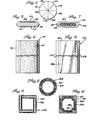
- Fig. 2 shipping cask 21 is illustrated with internal framing walls 46 and 52 therein, with quadrant shaped end neutron absorbing plates 74, 75, 77 and 79, made similar in construction to the absorbers of Fig's. 5 and 7, and with sectors of heat conductive material 81, 83, 85 and 87 at the ends thereof.
- thermally conductive end members 81, 83, 85 and 87 are of shorter heat transmitting thicknesses or lengths than members 37, 39, 41 and 43 of Fig. 1 because less heat needs be transmitted axially than radially and the area of contact of the heat transmitting plates with the ambient air is not increased by thickening them.
- FIG. 4 there are shown on shipping cask 21 thermally conductive portions and neutron absorbers at both ends.
- the conductive sectors are 89, 91, 93, 95, 97, 99, 101 and 103 and the neutron absorbing quadrants are 79, 77, 74 and 75.
- wall element or module 55 which may be employed interchangeably with other such walls, is shown. It comprises a base portion, shown as a solid metal base 56, and plasma sprayed radiation absorbing deposits 58 and 60 in undercuts therein, ground to smooth surfaces 62 and 64. Base 56 may also be hollow and may have boron carbide or other neutron or radiation absorber deposited thereon or may contain poison plates too, in addition to the surface coating of radiation absorber shown.
- Wall member 55 may be made by the method of S.N. 13,555) previously mentioned, and may have neutron absorber on only single wall faces.
- wall member 66 includes a casing portion 137 and an internal poison plate 139, preferably of boron carbide particles dispersed in a solid matrix of organic polymer, such as is described in one of the first six patent applications mentioned previously.
- an internal poison plate 139 preferably of boron carbide particles dispersed in a solid matrix of organic polymer, such as is described in one of the first six patent applications mentioned previously.
- the "sides" of wall 55 meet at 141 and 143 to form right angles, making such members readily fittable to other such members to form a plurality of tubular enclosures of square internal cross-section, in which fuel rods, etc. may be stored.
- other cross-sections e.g., rectangular, are also useful and are within this invention.
- FIG. 9 an alternative walled compartment structure 145 is illustrated with wall members 147 having "poison" deposits 149 contained therein.
- Fig. 10 shows another such compartment structure 151, with walled members 153, containing poison plates 155, overlapping similar members at ends thereof, as at 157. Also illustrated in such figure are additional corner strengthening members 159, each of which also contains a poison plate insert 161, so as to prevent "leakage" of neutrons through the compartment walls at corners thereof.
- Fig. 11 a variation of the invention is shown with a circular compartment 163 being illustrated, the wall portions 165 of which contain curved poison "plate” members 167.
- Fig. 12 depicts a shipping cask 169 having four compartments 171 for containing radioactive material, not shown, which compartments are made of modular wall units 173, each of which includes a base member 175 and an internal neutron absorbing deposit represented by numeral 177.
- Such units are in tight relationship with surrounding such units to facilitate heat conduction between them and have contacting surfaces 180 and 182 radially extending from the center of the cask, which is the center of the assembly of walled compartments for the radioactive material, e.g., spent nuclear fuel.
- Shipping cask 169 has radial fins 181 of conductive metal joined to members 179 to facilitate transfer of heat released by the radioactive material to the surroundings, e.g., air.
- Supports 183 hold the cask off the ground, truck bed, railroad car, concrete pad or other supporting surface, to facilitate external coolant circulation.
- shipping cask 185 is shown with only a single walled compartment 187 made up of four modular wall units 189, each of which contains a base portion 191 and a surface neutron absorbing deposit 193.
- the compartment 187 in thermally conductive contact with the walls thereof, are lead radiation absorbing members 195 and about them are copper or other suitable conductive members 197.
- the lead is for gamma ray absorption and the copper is for thermal conduction and dissipation.
- the radial planar contacting surfaces between the sections are continuous, as illustrated.
- the lead and copper or other suitable thermal conductor may be present in a suitable alloy or other alloys of radiation absorber and thermal conductor may be employed. However such alloying often adversely affects thermal conductivity.
- passageways 199 and 200 Through the lead and copper members are passageways 199 and 200, respectively, for coolant, useful when extra cooling capacity may be needed. Coolant flow may be decreased or halted when the radioactivity diminishes sufficiently to warrant such action.
- the illustrated unit is held together tightly by surrounding strap(s) 201 and turnbuckle or other suitable tightening device 203, or may often be welded together.
- the present invention is applicable to the manufacture of shipping and storage casks and other such containers for radioactive material which may include one or more compartments for such material.
- compartments of square cross-section are favored, those of other cross-sectional shapes may also be utilized.
- the compartments are tubular to accommodate nuclear fuel rods, either fresh or spent, but the invention is adaptable to the manufacture of other shapes of containers, e.g., cubic, spherical, toroidal, and for holding various other radioactive materials and products.
- four sub-assemblies or modules are preferably utilized, with or without an internal framework (or one or two framing members) for each of the modules, other numbers of modules, e.g., 2-12, may also be utilized.
- the number of compartments will be in the range of 4-32, but may be as great as 128, as when four sub-assemblies of 32 compartments each are employed. Preferably four sub-assemblies are present and thus, the number of compartments is divisible by four.
- the various portions of the different modules may be assembled permanently or removably, utilizing fastening techniques previously described, such as welding or cementing or the application of external or compacting pressures.
- the thermally conductive metal sheet, base envelope or casing which, together with the neutron absorbing material, forms a compartment wall, may include a neutron absorbing material, such as the plasma sprayed on boron carbide- metal mix of S.N.
- the thermally conductive outer members may have a poison plate inserted therein or may be of a construction of a combination of such devices.
- radial disposition of the joining surfaces of the thermally conductive outer members is highly preferable for most efficient conduction of heat away from the radioactive material, such surfaces may be otherwise located and shaped but it is desirable that they extend from the walls of the compartments to the exterior of the thermally conductive members, preferably in straight planes or smooth planar curves.
- a more highly conductive material inside the compartment wall between the wall exterior and any contained neutron absorber.
- a layer or plating of copper may be employed inside a stainless steel jacket.
- compatible alloys may be utilized for corrosion resistance and heat conductivity, e.g., alloys of iron, chromium, nickel and copper.
- each compartment or sub-assembly is often identical and at least two thermally conductive members of each cask should be identical.
- at least two sub-assemblies, each comprising at least one compartment or at least one thermally conductive member and preferably comprising at least one compartment and one conductive member should be identical and interchangeable.
- a cylindrical structure for the cask is highly preferred but other shapes, such as square, rectangular, oval, elliptical, octagonal, may also be employed.
- the individual compartments of the cask preferably utilize common walls but it is within the invention to assemble the compartments, each with its own walls, and then assemble the cask from them, so that some walls will be doubled.
- the cask will be tubular, preferably cylindrical and will be positioned or mounted horizontally, but it is within the invention to orient it otherwise, e.g., vertically.
- the compartments and conductive members may extend the length of the cask or may be made up of shorter members joined end to end to produce the desired cask length.
- the preferred materials of construction of various components, sub-assemblies and parts of this invention have been mentioned but it should be understood that others may also be employed.
- copper is a highly preferred conductor
- copper alloys such as brass and bronze may also be used, as may be aluminum, magnesium- aluminum alloys, titanium, silver and other conductive metals (with thermal conductivities like the metals previously recited) and similar materials, even stainless steel, in suitable circumstances.
- the compartment wall members may be of aluminum, copper, brass, bronze, stainless.steel, silver, steel or of various other metals and alloys in particular circumstances where they will be sufficiently corrosion resistant and conductive.
- Such walls may be plated with other such materials or alloys or may be clad with them.
- boron carbide in a form-retaining matrix such as a metal or alloy, e.g., copper, stainless steel, silver or aluminum, or a polymer, e.g., a phenolic polymer is a preferred neutron absorber other such neutron absorbers such as gadolinium, erbium and europium or any other neutron absorber of a capture cross-section greater than 200 Barns may also be employed.
- the boron carbide may be in particulate form or as metal borides, borates and equivalents.
- the poison plates with boron carbide or in separate poison plates in the compartment walL materials for absorbing harmful radiation other than neutrons, e.g., lead, uranium oxide, polyethylene.
- harmful radiation other than neutrons e.g., lead, uranium oxide, polyethylene.
- Such materials may also be in powder form, mixed with a neutron absorber in similar form.
- other means e.g., welding, surrounding cylinders, rings and cage-like frames.
- air or other heat transfer fluid may be driven into contact with the cask exterior (or suitable interior locations) by mechanical means, such as fans and pumps.
- Thermostatic control devices may be included in the casks for turning on such mechanical means and/or for pumping cooling fluid through the cask interior when the temperature rises above an acceptable limit, e.g., 90 0 C.
- the manufacture of the present casks is almost self- evident from the preceding description.
- it involves assembling together the wall members to form the walled longitudinal compartments for the radioactive material, making a sub-assembly of a plurality of such compartments and surrounding such sub-assembly at least on the side thereof intended to be on the outside in the final shipping cask, with a sub-assembly of a plurality of thermally conductive castings for conducting heat away from the compartments, or with separate such conductors.
- the interior walls of some of the compartments may be part of the framework of the interior framework of the shipping cask so that a quadrant, sub-assembly or module comprising compartment walls and heat conductive members may be produced, which may then be assembled with other such modules to form the final cask.
- the framework may include neutron and/or other radiation absorbers in forms like those previously described.
- the modular sub-assembly described may also be made, with neutron absorbing walls substituted for the framing part, and such sub-assembly may subsequently be combined with other such sub-assemblies to form the shipping cask, usually with the cask being held together by external means, such as strapping, welding or other such means previously described.
- the shipping cask in horizontal, vertical or inclined position, with one end opened, is filled with nuclear reactor fuel rods or other radioactive material, the end coverings are installed and bolted or otherwise fastened in place and the cask is set in desired, normally horizontal, position for transportation or storage.
- materials of construction such as those previously described and with the mentioned neutron absorber being utilized, designed for absorption of all harmful neutrons emitted from the radioactive material (and preferably with means for absorbing any other harmful radiation emitted)
- safe storage is possible for extended periods of time, up to 20 years and more.
- the modular construction of the various parts allows flexibility in manufacturing and assembling procedures and facilitates repair and replacement of parts, should that be needed. It also facilitates flexibility of design, it being possible to stock a number of different types of wall assemblies, each with a differs it neutron absorbing capability due to containing different absorber deposits or plates (or different strength absorbers of other radiation than neutrons) or containing no such absorbers. These may be assembled with other walls for best and most efficient use thereof.
- the modular, segmented cask structure with as many contact surfaces of the compartment walls and thermal conductors as feasible being radial or otherwise parallel (not transverse) to desired outward heat flow direction facilitates heat dissipation.
- joints and seams and any other discontinuities and thermal barrier surfaces should be parallel to heat flow direction (usually radial).
- the plasma deposited radiation absorber in a matrix of conductive metal also helps to dissipate heat from the nuclear fuel or other radioactive substance contained.
Landscapes
- Physics & Mathematics (AREA)
- Engineering & Computer Science (AREA)
- General Engineering & Computer Science (AREA)
- High Energy & Nuclear Physics (AREA)
- Particle Accelerators (AREA)
- Treatment Of Steel In Its Molten State (AREA)
- Radiation-Therapy Devices (AREA)
Applications Claiming Priority (2)
| Application Number | Priority Date | Filing Date | Title |
|---|---|---|---|
| US06/050,908 US4292528A (en) | 1979-06-21 | 1979-06-21 | Cask for radioactive material and method for preventing release of neutrons from radioactive material |
| US50908 | 1979-06-21 |
Publications (2)
| Publication Number | Publication Date |
|---|---|
| EP0020948A2 true EP0020948A2 (de) | 1981-01-07 |
| EP0020948A3 EP0020948A3 (de) | 1981-06-17 |
Family
ID=21968230
Family Applications (1)
| Application Number | Title | Priority Date | Filing Date |
|---|---|---|---|
| EP80102405A Withdrawn EP0020948A3 (de) | 1979-06-21 | 1980-05-02 | Behälter für radioaktives Material, Verfahren zur Herstellung eines derartigen Behälters, dabei verwendetes Bauelement und Verfahren zur Neutronenabschirmung |
Country Status (4)
| Country | Link |
|---|---|
| US (1) | US4292528A (de) |
| EP (1) | EP0020948A3 (de) |
| JP (1) | JPS566200A (de) |
| BR (1) | BR8003846A (de) |
Cited By (7)
| Publication number | Priority date | Publication date | Assignee | Title |
|---|---|---|---|---|
| EP0036982A1 (de) * | 1980-03-29 | 1981-10-07 | TRANSNUKLEAR GmbH | Einsatzkorb für radioaktives Material in Transport- und/oder Lagerbehältern |
| EP0062831A1 (de) * | 1981-04-11 | 1982-10-20 | Nukem GmbH | Behälter zur Langzeitlagerung von radioaktiven Stoffen (II) |
| EP0158849A1 (de) * | 1984-04-10 | 1985-10-23 | TRANSNUKLEAR GmbH | Einsatzkorb für Transport- und Lagerbehälter |
| GB2203377A (en) * | 1987-04-06 | 1988-10-19 | British Nuclear Fuels Plc | Flask for radioactive material |
| EP0314025A2 (de) * | 1987-10-30 | 1989-05-03 | Westinghouse Electric Corporation | Leichtgewichttitanbehälter zum Transport radioaktiven Materials |
| GB2525952A (en) * | 2013-12-10 | 2015-11-11 | Nuclear Cargo & Service Gmbh | Container |
| WO2016007200A1 (en) | 2014-07-10 | 2016-01-14 | Energysolutions, Llc | Shielded packaging system for radioactive waste |
Families Citing this family (36)
| Publication number | Priority date | Publication date | Assignee | Title |
|---|---|---|---|---|
| DE7833030U1 (de) * | 1978-11-07 | 1979-03-08 | Transnuklear Gmbh, 6450 Hanau | Einsatzkorb fuer abgebrannte kernbrennelemente in transport- und/oder lagerbehaeltern |
| DE3103526C2 (de) * | 1981-02-03 | 1985-11-14 | Deutsche Gesellschaft für Wiederaufarbeitung von Kernbrennstoffen mbH, 3000 Hannover | Mehrschichtiger Transport- und Lagerbehälter für radioaktive Abfälle |
| US4399366A (en) * | 1981-04-24 | 1983-08-16 | Bucholz James A | Separator assembly for use in spent nuclear fuel shipping cask |
| JPS58118992A (ja) * | 1982-01-06 | 1983-07-15 | 三菱重工業株式会社 | 核燃料集合体の貯蔵装置 |
| EP0116412A1 (de) * | 1983-01-18 | 1984-08-22 | Kabushiki Kaisha Kobe Seiko Sho | Behälter für radioaktive Materialien und Verfahren zur Herstellung |
| DE3310233A1 (de) * | 1983-03-22 | 1984-10-04 | Strabag Bau-AG, 5000 Köln | Behaeltnis zur lagerung radioaktiver elemente |
| US4666659A (en) * | 1983-10-25 | 1987-05-19 | Mitsubishi Heavy Industries, Ltd. | Shipping and storage container for spent nuclear fuel |
| US4780268A (en) * | 1984-06-13 | 1988-10-25 | Westinghouse Electric Corp. | Neutron absorber articles |
| DE3513692A1 (de) * | 1985-04-16 | 1986-10-30 | Kraftwerk Union AG, 4330 Mülheim | Verfahren zum herstellen endlagerfaehiger gebinde mit radioaktiven abfaellen und nach diesem verfahren hergestellte gebinde |
| CH667880A5 (fr) * | 1986-07-30 | 1988-11-15 | Claude Planchamp | Absorbeur de radiations nucleaires. |
| US4800283A (en) * | 1987-05-01 | 1989-01-24 | Westinghouse Electric Corp. | Shock-absorbing and heat conductive basket for use in a fuel rod transportation cask |
| US4770844A (en) * | 1987-05-01 | 1988-09-13 | Westinghouse Electric Corp. | Basket structure for a nuclear fuel transportation cask |
| US5061858A (en) * | 1987-10-19 | 1991-10-29 | Westinghouse Electric Corp. | Cask assembly for transporting radioactive material of different intensities |
| DE4402282C1 (de) * | 1994-01-27 | 1995-04-13 | Apparate Und Anlagenbau Gmbh | Verfahren zur Herstellung einer Schweißverbindung und nach diesem Verfahren hergestellter Transport- und Lagerbehälter für abgebrannte Kernbrennstoffkassetten |
| US5406601A (en) * | 1994-05-02 | 1995-04-11 | The Babcock & Wilcox Company | Transport and storage cask for spent nuclear fuel |
| US6332906B1 (en) | 1998-03-24 | 2001-12-25 | California Consolidated Technology, Inc. | Aluminum-silicon alloy formed from a metal powder |
| US5965829A (en) * | 1998-04-14 | 1999-10-12 | Reynolds Metals Company | Radiation absorbing refractory composition |
| RU2133990C1 (ru) * | 1998-06-15 | 1999-07-27 | Курносов Владимир Александрович | Защитное сооружение для радиоактивных веществ, способ и материал для его изготовления |
| JP3122436B1 (ja) * | 1999-09-09 | 2001-01-09 | 三菱重工業株式会社 | アルミニウム複合材およびその製造方法、並びにそれを用いたバスケットおよびキャスク |
| US6544606B1 (en) * | 2000-01-11 | 2003-04-08 | Nac International | Systems and methods for storing fissile materials |
| US6730180B1 (en) * | 2000-09-26 | 2004-05-04 | Bechtel Bwxt Idaho, Llc | Neutron absorbing alloys |
| JP3600535B2 (ja) * | 2001-02-26 | 2004-12-15 | 三菱重工業株式会社 | キャスク |
| US6741669B2 (en) | 2001-10-25 | 2004-05-25 | Kenneth O. Lindquist | Neutron absorber systems and method for absorbing neutrons |
| US7286626B2 (en) * | 2005-12-15 | 2007-10-23 | Battelle Energy Alliance, Llc | Neutron absorbing coating for nuclear criticality control |
| US20080249347A1 (en) * | 2007-04-04 | 2008-10-09 | William Gregory Broda | Waste Stabilization and Packaging System for Fissile Isotope-Laden Wastes |
| FR2923470B1 (fr) * | 2007-11-12 | 2013-08-02 | Guillaume Yves Remi Crochemore | Serie d'emballages pour dispositifs sensibles ou dangereux ou bien pour matieres dangereuses plus particulierement radioactives. |
| FR2925975B1 (fr) * | 2007-12-26 | 2016-05-27 | Areva Np | Conteneur de transport pour assemblage de combustible nucleaire, et procede de transport d'un assemblage de combustible nucleaire |
| FR2935532B1 (fr) * | 2008-08-27 | 2012-07-13 | Tn Int | Procede de fabrication d'un emballage pour le transport et/ou stockage de matieres nucleaires, utilisant le phenomene de retrait de soudage. |
| GB0906143D0 (en) * | 2009-04-09 | 2009-05-20 | Nuvia Ltd | Radioactive waste storage |
| US11515054B2 (en) | 2011-08-19 | 2022-11-29 | Holtec International | Method of retrofitting a spent nuclear fuel storage system |
| US9748009B2 (en) * | 2011-08-19 | 2017-08-29 | Holtec International | Container and system for handling damaged nuclear fuel, and method of making the same |
| US20140361198A1 (en) * | 2011-12-08 | 2014-12-11 | Atomic Energy Of Canada Limited/Énergie Atomique Du Canada Limitée | Apparatus for holding radioactive objects |
| JP5998008B2 (ja) * | 2012-10-19 | 2016-09-28 | 日軽金アクト株式会社 | 中性子吸収材およびその製造方法 |
| CN106782714A (zh) * | 2017-01-10 | 2017-05-31 | 上海核工程研究设计院 | 一种用于乏燃料组件的内插式中子吸收组件 |
| GB2574178B (en) * | 2018-02-16 | 2022-07-13 | Water Lane 6 Sf Ltd | Thermal Management |
| KR102004182B1 (ko) | 2018-10-31 | 2019-07-26 | 한국원자력환경공단 | 다중 방벽을 이용한 고준위 방사성 폐기물의 처분 용기 및 이를 이용한 방벽 시스템 |
Citations (7)
| Publication number | Priority date | Publication date | Assignee | Title |
|---|---|---|---|---|
| US2727996A (en) * | 1952-08-11 | 1955-12-20 | Iii Theodore Rockwell | Thermal neutron shield and method for making same |
| US2935616A (en) * | 1955-02-14 | 1960-05-03 | Farrel Birmingham Co Inc | Radiation shielding container |
| US3667540A (en) * | 1968-09-03 | 1972-06-06 | Robert W Kupp | Heat removal system for nuclear fuel assemblies |
| US3845315A (en) * | 1970-11-17 | 1974-10-29 | Transports De L Ind Soc Pour | Packaging for the transportation of radioactive materials |
| GB1408396A (en) * | 1971-11-15 | 1975-10-01 | Commissariat Energie Atomique | Device for the transporting of heat-emitting radiactive products |
| US3976809A (en) * | 1973-08-13 | 1976-08-24 | Dowell Robert D | Coating for metal surfaces and method for application |
| EP0002227A1 (de) * | 1977-11-25 | 1979-06-13 | The Carborundum Company | Neutronen absorbierendes Element, Neutronen absorbierende Platte, die Verwendung dieser Platte sowie Verfahren zur Herstellung des Elements |
Family Cites Families (3)
| Publication number | Priority date | Publication date | Assignee | Title |
|---|---|---|---|---|
| BE583252A (de) * | 1958-10-17 | |||
| US3119933A (en) * | 1960-05-03 | 1964-01-28 | Stanray Corp | Container for transporting thermally hot intensely radioactive material |
| US4096392A (en) * | 1975-07-11 | 1978-06-20 | Nuclear Services Corporation | Rack for storing spent nuclear fuel elements |
-
1979
- 1979-06-21 US US06/050,908 patent/US4292528A/en not_active Expired - Lifetime
-
1980
- 1980-05-02 EP EP80102405A patent/EP0020948A3/de not_active Withdrawn
- 1980-06-19 JP JP8221280A patent/JPS566200A/ja active Pending
- 1980-06-20 BR BR8003846A patent/BR8003846A/pt unknown
Patent Citations (7)
| Publication number | Priority date | Publication date | Assignee | Title |
|---|---|---|---|---|
| US2727996A (en) * | 1952-08-11 | 1955-12-20 | Iii Theodore Rockwell | Thermal neutron shield and method for making same |
| US2935616A (en) * | 1955-02-14 | 1960-05-03 | Farrel Birmingham Co Inc | Radiation shielding container |
| US3667540A (en) * | 1968-09-03 | 1972-06-06 | Robert W Kupp | Heat removal system for nuclear fuel assemblies |
| US3845315A (en) * | 1970-11-17 | 1974-10-29 | Transports De L Ind Soc Pour | Packaging for the transportation of radioactive materials |
| GB1408396A (en) * | 1971-11-15 | 1975-10-01 | Commissariat Energie Atomique | Device for the transporting of heat-emitting radiactive products |
| US3976809A (en) * | 1973-08-13 | 1976-08-24 | Dowell Robert D | Coating for metal surfaces and method for application |
| EP0002227A1 (de) * | 1977-11-25 | 1979-06-13 | The Carborundum Company | Neutronen absorbierendes Element, Neutronen absorbierende Platte, die Verwendung dieser Platte sowie Verfahren zur Herstellung des Elements |
Non-Patent Citations (1)
| Title |
|---|
| REPORT LA-3570-MS, LOS ALAMOS Scientific Laboratory of the University of Cali-fornia, December 1965, R.W. Keil et al.: "Feadibility study for fabrication ofCu-B4 sheet" Page 3, page 19, page 22 * |
Cited By (13)
| Publication number | Priority date | Publication date | Assignee | Title |
|---|---|---|---|---|
| EP0036982A1 (de) * | 1980-03-29 | 1981-10-07 | TRANSNUKLEAR GmbH | Einsatzkorb für radioaktives Material in Transport- und/oder Lagerbehältern |
| EP0062831A1 (de) * | 1981-04-11 | 1982-10-20 | Nukem GmbH | Behälter zur Langzeitlagerung von radioaktiven Stoffen (II) |
| EP0158849A1 (de) * | 1984-04-10 | 1985-10-23 | TRANSNUKLEAR GmbH | Einsatzkorb für Transport- und Lagerbehälter |
| GB2203377A (en) * | 1987-04-06 | 1988-10-19 | British Nuclear Fuels Plc | Flask for radioactive material |
| GB2203377B (en) * | 1987-04-06 | 1990-03-28 | British Nuclear Fuels Plc | Improvements in flasks for radioactive materials. |
| US4877969A (en) * | 1987-04-06 | 1989-10-31 | British Nuclear Fuels Plc | Flasks for radioactive materials |
| EP0314025A3 (de) * | 1987-10-30 | 1989-12-06 | Westinghouse Electric Corporation | Leichtgewichttitanbehälter zum Transport radioaktiven Materials |
| EP0314025A2 (de) * | 1987-10-30 | 1989-05-03 | Westinghouse Electric Corporation | Leichtgewichttitanbehälter zum Transport radioaktiven Materials |
| GB2525952A (en) * | 2013-12-10 | 2015-11-11 | Nuclear Cargo & Service Gmbh | Container |
| WO2016007200A1 (en) | 2014-07-10 | 2016-01-14 | Energysolutions, Llc | Shielded packaging system for radioactive waste |
| CN106575531A (zh) * | 2014-07-10 | 2017-04-19 | P&T全球解决方案有限责任公司 | 用于放射性废物的屏蔽包装系统 |
| EP3167453A4 (de) * | 2014-07-10 | 2018-02-21 | P&T Global Solutions, LLC | Abgeschirmtes verpackungssystem für radioaktive abfälle |
| EP3167453B1 (de) | 2014-07-10 | 2022-04-20 | P&T Global Solutions, LLC | Abgeschirmtes verpackungssystem für radioaktive abfälle |
Also Published As
| Publication number | Publication date |
|---|---|
| EP0020948A3 (de) | 1981-06-17 |
| US4292528A (en) | 1981-09-29 |
| JPS566200A (en) | 1981-01-22 |
| BR8003846A (pt) | 1981-01-13 |
Similar Documents
| Publication | Publication Date | Title |
|---|---|---|
| US4292528A (en) | Cask for radioactive material and method for preventing release of neutrons from radioactive material | |
| EP0757361B1 (de) | Transport- und Lagerungsbehälter für radioaktive Stoffe | |
| US9672948B2 (en) | Cask apparatus, system and method for transporting and/or storing high level waste | |
| EP1016091B1 (de) | Apparat, geeignet zum transport und lagerung von kernbrennstoffstäben und verfahren zur verwendung des apparats | |
| US3727060A (en) | Package for the storage and transportation of radioactive substances containing both neutron and gamma radiation absorbing material | |
| US5015863A (en) | Radiation shield and shielding material with excellent heat-transferring property | |
| JP2924916B2 (ja) | 使用済み核燃料の輸送用バスケット及びこのバスケットを収納するキャスク | |
| US3780306A (en) | Radioactive shipping container with neutron and gamma absorbers | |
| US3962587A (en) | Shipping cask for spent nuclear fuel assemblies | |
| RU2348085C1 (ru) | Контейнер для транспортировки и/или хранения отработавшего ядерного топлива | |
| DE3515871A1 (de) | Transport- und lagerbehaelter fuer brennelemente | |
| WO2002059904A1 (en) | Cask and production method for cask | |
| US3119933A (en) | Container for transporting thermally hot intensely radioactive material | |
| WO2004017331A1 (ja) | キャスク及びキャスクの製造方法 | |
| JP2002250790A (ja) | キャスク | |
| WO2001018823A1 (fr) | Château de transport | |
| GB2048149A (en) | Shielding container for transporting and/or storing burnt-up fuel elements | |
| US5909475A (en) | Spent nuclear fuel container | |
| US5995573A (en) | Dry storage arrangement for spent nuclear fuel containers | |
| JP4082179B2 (ja) | 使用済核燃料収納容器 | |
| US3016462A (en) | Multi-layer vessel having a gamma ray flux absorbing layer | |
| US3727059A (en) | Container for transporting radioactive materials | |
| GB2165795A (en) | Spent fuel storage cask having improved fins | |
| JP2001318187A (ja) | キャスク | |
| JP2692173B2 (ja) | 使用済燃料用キャスク及び該キャスクに用いるバスケット |
Legal Events
| Date | Code | Title | Description |
|---|---|---|---|
| PUAI | Public reference made under article 153(3) epc to a published international application that has entered the european phase |
Free format text: ORIGINAL CODE: 0009012 |
|
| AK | Designated contracting states |
Designated state(s): BE DE FR GB SE |
|
| PUAL | Search report despatched |
Free format text: ORIGINAL CODE: 0009013 |
|
| DET | De: translation of patent claims | ||
| AK | Designated contracting states |
Designated state(s): BE DE FR GB SE |
|
| 17P | Request for examination filed |
Effective date: 19811214 |
|
| STAA | Information on the status of an ep patent application or granted ep patent |
Free format text: STATUS: THE APPLICATION IS DEEMED TO BE WITHDRAWN |
|
| 18D | Application deemed to be withdrawn |
Effective date: 19840112 |
|
| RIN1 | Information on inventor provided before grant (corrected) |
Inventor name: SHAFFER, PETER THOMAS BARNUM, SR. Inventor name: GAFFNEY, MICHAEL FRANCIS |