EP0020187A1 - Arrangement of a deaeration chamber in a cooling system for an internal-combustion engine - Google Patents
Arrangement of a deaeration chamber in a cooling system for an internal-combustion engine Download PDFInfo
- Publication number
- EP0020187A1 EP0020187A1 EP19800400414 EP80400414A EP0020187A1 EP 0020187 A1 EP0020187 A1 EP 0020187A1 EP 19800400414 EP19800400414 EP 19800400414 EP 80400414 A EP80400414 A EP 80400414A EP 0020187 A1 EP0020187 A1 EP 0020187A1
- Authority
- EP
- European Patent Office
- Prior art keywords
- degassing box
- box
- arrangement
- degassing
- circuit
- Prior art date
- Legal status (The legal status is an assumption and is not a legal conclusion. Google has not performed a legal analysis and makes no representation as to the accuracy of the status listed.)
- Granted
Links
Images

Classifications
-
- F—MECHANICAL ENGINEERING; LIGHTING; HEATING; WEAPONS; BLASTING
- F01—MACHINES OR ENGINES IN GENERAL; ENGINE PLANTS IN GENERAL; STEAM ENGINES
- F01P—COOLING OF MACHINES OR ENGINES IN GENERAL; COOLING OF INTERNAL-COMBUSTION ENGINES
- F01P11/00—Component parts, details, or accessories not provided for in, or of interest apart from, groups F01P1/00 - F01P9/00
- F01P11/04—Arrangements of liquid pipes or hoses
-
- F—MECHANICAL ENGINEERING; LIGHTING; HEATING; WEAPONS; BLASTING
- F01—MACHINES OR ENGINES IN GENERAL; ENGINE PLANTS IN GENERAL; STEAM ENGINES
- F01P—COOLING OF MACHINES OR ENGINES IN GENERAL; COOLING OF INTERNAL-COMBUSTION ENGINES
- F01P11/00—Component parts, details, or accessories not provided for in, or of interest apart from, groups F01P1/00 - F01P9/00
- F01P11/02—Liquid-coolant filling, overflow, venting, or draining devices
- F01P11/029—Expansion reservoirs
Definitions
- the present invention is due to the collaboration of Mr. Gilles BAILLEUX,
- It relates to a liquid cooling circuit of a heat engine, in particular on a motor vehicle. More specifically, it relates to the arrangement of the degassing box with which such a circuit is provided.
- the invention proposes to overcome this drawback by means of a simple arrangement providing good access to the filling orifice, even when the degassing box is placed below and at a very short distance from a fixed part.
- the liquid cooling circuit of a heat engine comprising a degassing box provided with a filling plug and connected to said circuit by at least one flexible duct, is characterized in that the degassing box is mounted on a support articulated around a fixed axis, in order to authorize a limited tilting of the degassing box, allowing access to the filling plug.
- the invention is applied to a utility vehicle 1, with an advanced cabin, of which the windshield 2, the dashboard 3, the steering wheel 4 and the hood 5 enveloping the engine have been shown. .
- This engine comprises, in a conventional manner, a liquid cooling circuit comprising, in particular, a radiator 6, a circulation pump 7 and a degassing box 8.
- the latter is connected, by two flexible conduits 9 and 10, of on the one hand to the radiator 6, on the other hand, to the pump 7, and it includes a filling plug 11.
- the degassing box is disposed between an apron 12 and a grille 13, so that the plug 11 is located below, and at a short distance, from a substantially horizontal sheet metal 14.
- the degassing box 8 is carried by a tilting support constituted by two arms 15, 16 articulated on two pegs 17,18 carried by sheets 19, 20 substantially vertical.
- the grille 13 is removable and, when it is in place, the degassing box 8 is immobilized by two studs 21, 22 made of elastic material, fixed respectively on the bulkhead 12 and on the grille 13.
- the degassing box 8 can be tilted forward, this tilting movement being limited by pressing the arm 15 against a folded edge 23 of the sheet 19.
- the plug 11 is released from the horizontal sheet 14 which makes it very easy to fill the cooling circuit or, simply, to control the level of the liquid.
Abstract
Description
La présente invention est due à la collaboration de Monsieur Gilles BAILLEUX,The present invention is due to the collaboration of Mr. Gilles BAILLEUX,
Elle concerne un circuit de refroidissement par liquide d'un moteur thermique, notamment sur un véhicule automobile. De façon plus précise, elle concerne l'agencement de la boîte de dégazage dont est muni un tel circuit.It relates to a liquid cooling circuit of a heat engine, in particular on a motor vehicle. More specifically, it relates to the arrangement of the degassing box with which such a circuit is provided.
Il est en effet nécessaire, sur un circuit de refroidissement par liquide d'un moteur thermique, de prévoir une boîte de dégazage destinée à recueillir les gaz qui peuvent apparaître en un point quelconque du circuit. Cette boîte doit être placée en partie haute, par rapport au reste du circuit, et elle comporte habituellement un bouchon fermant un orifice par lequel se fait le remplissage en liquide.It is indeed necessary, on a liquid cooling circuit of a heat engine, to provide a degassing box intended to collect the gases which may appear at any point of the circuit. This box must be placed in the upper part, relative to the rest of the circuit, and it usually includes a plug closing an orifice through which the liquid is filled.
Or, il peut arriver que, par manque de place, ledit orifice soit d'accès particulièrement difficile.However, it may happen that, for lack of space, said orifice is particularly difficult to access.
L'invention se propose de remédier à cet inconvénient grâce à un agencement simple procurant un bon accès à l'orifice de remplissage, même lorsque la boîte de dégazage est disposée en dessous et à une très faible distance d'une partie fixe.The invention proposes to overcome this drawback by means of a simple arrangement providing good access to the filling orifice, even when the degassing box is placed below and at a very short distance from a fixed part.
Suivant l'invention, le circuit de refroidissement par liquide d'un moteur thermique, comportant une bofte de dégazage munie d'un bouchon de remplissage et reliée audit circuit par au moins un conduit souple, est caractérisé en ce que la boîte de dégazage est montée sur un support articulé autour d'un axe fixe, en vue d'autoriser un basculement limité de la boîte de dégazage, permettant d'accéder au bouchon de remplissage.According to the invention, the liquid cooling circuit of a heat engine, comprising a degassing box provided with a filling plug and connected to said circuit by at least one flexible duct, is characterized in that the degassing box is mounted on a support articulated around a fixed axis, in order to authorize a limited tilting of the degassing box, allowing access to the filling plug.
Un exemple de réalisation de l'invention fait l'objet de la description qui suit, en référence aux dessins joints dans lesquels :
- - la Fig. 1 est une vue de face partielle d'un véhicule montrant un circuit de refroidissement agencé suivant l'invention ;
- - la Fig. 2 est une coupe suivant la ligne 2-2 de la Fig, 1.
- - Fig. 1 is a partial front view of a vehicle showing a cooling circuit arranged according to the invention;
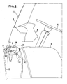
- - Fig. 2 is a section along line 2-2 of FIG, 1.
Dans l'exemple décrit, l'invention est appliquée à un véhicule utilitaire 1, à cabine avancée, dont on a notamment représenté le pare-brise 2, le tableau de bord 3, le volant de direction 4 et le capot 5 enveloppant le moteur.In the example described, the invention is applied to a utility vehicle 1, with an advanced cabin, of which the
Ce moteur comporte, de façon classique, un circuit de refroidissement par liquide comportant, en particulier, un radiateur 6, une pompe de circulation 7 et une boîte de dégazage 8. Cette dernière est reliée, par deux conduits souples 9 et 10, d'une part au radiateur 6, d'autre part, à la pompe 7, et elle comporte un bouchon de remplissage 11.This engine comprises, in a conventional manner, a liquid cooling circuit comprising, in particular, a radiator 6, a
Comme il apparaît sur la Fig. 2, la boite de dégazage est disposée entre un tablier 12 et une calandre 13, de telle sorte que le bouchon 11 se trouve au-dessous, et à une courte distance, d'une tôle de structure 14, sensiblement horizontale.As it appears in FIG. 2, the degassing box is disposed between an
Suivant l'invention, la boîte de dégazage 8 est portée par un support basculant constitué par deux bras 15, 16 articulés sur deux chevilles 17,18 portées par des tôles 19, 20 sensiblement verticales.According to the invention, the
Comme il est classique sur ce genre de véhicule, la calandre 13 est amovible et, lorsqu'elle est en place, la boite de dégazage 8 est immobilisée par deux plots 21, 22 en matière élastique, fixés respectivement sur le tablier 12 et sur la calandre 13.As is conventional on this type of vehicle, the
Lorsque cette dernière est déposée, la boite de dégazage 8 peut être basculée vers l'avant, ce mouvement de basculement étant limité par appui du bras 15 contre un bord plié 23 de la tôle 19. Dans la position basculée vers l'avant, comme représenté en trait mixte sur la Fig. 2, le bouchon 11 se trouve dégagé de la tôle horizontale 14 ce qui permet très facilement de faire le remplissage du circuit de refroidissement ou, simplement, de contrôler le niveau du liquide.When the latter is deposited, the
Claims (4)
Applications Claiming Priority (2)
| Application Number | Priority Date | Filing Date | Title |
|---|---|---|---|
| FR7914320A FR2458679A1 (en) | 1979-06-05 | 1979-06-05 | ARRANGEMENT OF A DEGASSING BOX COMPRISING A COOLING CIRCUIT FOR A THERMAL ENGINE |
| FR7914320 | 1979-06-05 |
Publications (2)
| Publication Number | Publication Date |
|---|---|
| EP0020187A1 true EP0020187A1 (en) | 1980-12-10 |
| EP0020187B1 EP0020187B1 (en) | 1982-11-03 |
Family
ID=9226227
Family Applications (1)
| Application Number | Title | Priority Date | Filing Date |
|---|---|---|---|
| EP19800400414 Expired EP0020187B1 (en) | 1979-06-05 | 1980-03-28 | Arrangement of a deaeration chamber in a cooling system for an internal-combustion engine |
Country Status (3)
| Country | Link |
|---|---|
| EP (1) | EP0020187B1 (en) |
| DE (1) | DE3061026D1 (en) |
| FR (1) | FR2458679A1 (en) |
Cited By (6)
| Publication number | Priority date | Publication date | Assignee | Title |
|---|---|---|---|---|
| FR2587976A1 (en) * | 1985-09-27 | 1987-04-03 | Renault | Device for filling a reservoir such as the radiator of a motor vehicle |
| EP1255029A1 (en) * | 2001-05-04 | 2002-11-06 | Renault s.a.s. | Sub-assembly for a motor vehicle with an expansion tank |
| FR2891796A1 (en) * | 2005-10-11 | 2007-04-13 | Renault Sas | Motor vehicle component located in engine compartment has support fixed to chassis and pivot in line with connector to allow ease of access |
| CN101793188A (en) * | 2010-03-30 | 2010-08-04 | 奇瑞汽车股份有限公司 | Expansion tank |
| FR3099725A1 (en) * | 2019-08-05 | 2021-02-12 | Psa Automobiles Sa | Motor vehicle assembly comprising a degassing box |
| FR3099726A1 (en) * | 2019-08-05 | 2021-02-12 | Psa Automobiles Sa | Motor vehicle assembly comprising a degassing box |
Families Citing this family (3)
| Publication number | Priority date | Publication date | Assignee | Title |
|---|---|---|---|---|
| US5456576A (en) * | 1994-08-31 | 1995-10-10 | United Technologies Corporation | Dynamic control of tip clearance |
| FR2951679B1 (en) | 2009-10-27 | 2011-11-04 | Peugeot Citroen Automobiles Sa | CONTAINER FOR A MOTOR VEHICLE, IN PARTICULAR A DEGASS BOX OR A WASHER FLUID RESERVOIR |
| FR2964148A1 (en) | 2010-08-30 | 2012-03-02 | Peugeot Citroen Automobiles Sa | DEGASSING BOX FOR THE COOLING SYSTEM OF A THERMAL MOTOR OF A MOTOR VEHICLE |
Citations (3)
| Publication number | Priority date | Publication date | Assignee | Title |
|---|---|---|---|---|
| FR1269341A (en) * | 1960-07-02 | 1961-08-11 | Renault | Device for sealing the hydraulic engine cooling circuit |
| US3238932A (en) * | 1964-03-30 | 1966-03-08 | Ford Motor Co | Sealed cooling system for an internal combustion engine |
| AT340206B (en) * | 1976-02-11 | 1977-12-12 | Steyr Daimler Puch Ag | HOSE CONNECTION BETWEEN THE COOLER AND THE ABOVE THIS EXPANSION TANK FOR THE COOLING LIQUID OF MOTOR VEHICLE ENGINES |
-
1979
- 1979-06-05 FR FR7914320A patent/FR2458679A1/en active Granted
-
1980
- 1980-03-28 DE DE8080400414T patent/DE3061026D1/en not_active Expired
- 1980-03-28 EP EP19800400414 patent/EP0020187B1/en not_active Expired
Patent Citations (4)
| Publication number | Priority date | Publication date | Assignee | Title |
|---|---|---|---|---|
| FR1269341A (en) * | 1960-07-02 | 1961-08-11 | Renault | Device for sealing the hydraulic engine cooling circuit |
| FR80507E (en) * | 1960-07-02 | 1963-05-10 | Renault | Device for sealing the hydraulic engine cooling circuit |
| US3238932A (en) * | 1964-03-30 | 1966-03-08 | Ford Motor Co | Sealed cooling system for an internal combustion engine |
| AT340206B (en) * | 1976-02-11 | 1977-12-12 | Steyr Daimler Puch Ag | HOSE CONNECTION BETWEEN THE COOLER AND THE ABOVE THIS EXPANSION TANK FOR THE COOLING LIQUID OF MOTOR VEHICLE ENGINES |
Cited By (7)
| Publication number | Priority date | Publication date | Assignee | Title |
|---|---|---|---|---|
| FR2587976A1 (en) * | 1985-09-27 | 1987-04-03 | Renault | Device for filling a reservoir such as the radiator of a motor vehicle |
| EP1255029A1 (en) * | 2001-05-04 | 2002-11-06 | Renault s.a.s. | Sub-assembly for a motor vehicle with an expansion tank |
| FR2824309A1 (en) * | 2001-05-04 | 2002-11-08 | Renault | MOTOR VEHICLE SUB-ASSEMBLY HAVING AN EXPANSION VESSEL |
| FR2891796A1 (en) * | 2005-10-11 | 2007-04-13 | Renault Sas | Motor vehicle component located in engine compartment has support fixed to chassis and pivot in line with connector to allow ease of access |
| CN101793188A (en) * | 2010-03-30 | 2010-08-04 | 奇瑞汽车股份有限公司 | Expansion tank |
| FR3099725A1 (en) * | 2019-08-05 | 2021-02-12 | Psa Automobiles Sa | Motor vehicle assembly comprising a degassing box |
| FR3099726A1 (en) * | 2019-08-05 | 2021-02-12 | Psa Automobiles Sa | Motor vehicle assembly comprising a degassing box |
Also Published As
| Publication number | Publication date |
|---|---|
| FR2458679B1 (en) | 1983-03-18 |
| EP0020187B1 (en) | 1982-11-03 |
| FR2458679A1 (en) | 1981-01-02 |
| DE3061026D1 (en) | 1982-12-09 |
Similar Documents
| Publication | Publication Date | Title |
|---|---|---|
| EP0020187A1 (en) | Arrangement of a deaeration chamber in a cooling system for an internal-combustion engine | |
| EP0311466B1 (en) | Structure of a motor vehicle having an integrated body and frame and its procedure of assembly | |
| EP1755936B1 (en) | Arrangement for a spare wheel in a motor vehicle | |
| US4506750A (en) | Pivotal hood arrangement | |
| EP1048521B1 (en) | Optical block mounting device on vehicle body parts | |
| FR2788250A1 (en) | ARRANGEMENT FOR THE STRUCTURE OF A FRONT BODY PART OF A MOTOR VEHICLE | |
| EP0334755B1 (en) | Concealable windshield-wiper arrangement, adapted to be fitted, for instance on an automobile vehicle | |
| EP2001732B1 (en) | Method for mounting underbody elements on a motor vehicle | |
| FR2571013A1 (en) | Fairing for a steered wheel of a motor vehicle | |
| EP0011000B1 (en) | Guiding device for the lateral wings of a bumper on an automotive vehicle | |
| EP0086690B1 (en) | Storage device for a road vehicle spare wheel | |
| EP1018448B1 (en) | Device for the suspension of a propulsion unit to the vehicle body | |
| EP1592603B1 (en) | Front pillar structure of a motor vehicle | |
| FR3106122A1 (en) | Centering shoe device for vehicle center console and associated mounting method | |
| EP1093954B1 (en) | Device for mounting an electronic calculator on the motor of an automotive vehicle | |
| FR2610177A1 (en) | ASHTRAY ASHTRAY FOR MOTOR VEHICLE | |
| EP3800112B1 (en) | Motor vehicle comprising a system for protecting the fuel tank | |
| FR2622521A1 (en) | Set of rear-view mirrors (retrovisors) for commercial vehicles | |
| EP1407946A1 (en) | Vehicle windscreen wiper device and method for mounting on a vehicle body | |
| EP0328437B1 (en) | Electrical connecting device and control system of a motor vehicle brake unit equipped with this device | |
| FR2892079A1 (en) | Motor vehicle body has bonnet with rear edge that collapses and windscreen that shatters to reduce injury to pedestrian in event of collision | |
| FR2620542A1 (en) | Motor vehicle constructed by assembling modules of the type including a brake and/or clutch control member integral with the cradle for the mechanical assembly | |
| FR3137347A1 (en) | Liquid tank for a motor vehicle comprising masking means. | |
| FR3089889A1 (en) | PEDAL BOX FOR MOTOR VEHICLE WITH SIMPLIFIED ELECTRICAL CONNECTION | |
| FR3126957A1 (en) | Motor vehicle hood liner |
Legal Events
| Date | Code | Title | Description |
|---|---|---|---|
| PUAI | Public reference made under article 153(3) epc to a published international application that has entered the european phase |
Free format text: ORIGINAL CODE: 0009012 |
|
| 17P | Request for examination filed | ||
| AK | Designated contracting states |
Designated state(s): DE GB IT |
|
| ITF | It: translation for a ep patent filed |
Owner name: FUMERO BREVETTI S.N.C. |
|
| GRAA | (expected) grant |
Free format text: ORIGINAL CODE: 0009210 |
|
| AK | Designated contracting states |
Designated state(s): DE GB IT |
|
| REF | Corresponds to: |
Ref document number: 3061026 Country of ref document: DE Date of ref document: 19821209 |
|
| ITPR | It: changes in ownership of a european patent |
Owner name: OFFERTA DI LICENZA AL PUBBLICO |
|
| REG | Reference to a national code |
Ref country code: GB Ref legal event code: 746 |
|
| ITTA | It: last paid annual fee | ||
| PGFP | Annual fee paid to national office [announced via postgrant information from national office to epo] |
Ref country code: DE Payment date: 19980219 Year of fee payment: 19 |
|
| PGFP | Annual fee paid to national office [announced via postgrant information from national office to epo] |
Ref country code: GB Payment date: 19980320 Year of fee payment: 19 |
|
| PG25 | Lapsed in a contracting state [announced via postgrant information from national office to epo] |
Ref country code: GB Free format text: LAPSE BECAUSE OF NON-PAYMENT OF DUE FEES Effective date: 19990328 |
|
| GBPC | Gb: european patent ceased through non-payment of renewal fee |
Effective date: 19990328 |
|
| PG25 | Lapsed in a contracting state [announced via postgrant information from national office to epo] |
Ref country code: DE Free format text: LAPSE BECAUSE OF NON-PAYMENT OF DUE FEES Effective date: 20000101 |
|
| PLBE | No opposition filed within time limit |
Free format text: ORIGINAL CODE: 0009261 |
|
| STAA | Information on the status of an ep patent application or granted ep patent |
Free format text: STATUS: NO OPPOSITION FILED WITHIN TIME LIMIT |