EP0020003A2 - Procédé et dispositif pour découper et transférer le profil d'une feuille de tabac ayant un contour déterminé - Google Patents
Procédé et dispositif pour découper et transférer le profil d'une feuille de tabac ayant un contour déterminé Download PDFInfo
- Publication number
- EP0020003A2 EP0020003A2 EP80301190A EP80301190A EP0020003A2 EP 0020003 A2 EP0020003 A2 EP 0020003A2 EP 80301190 A EP80301190 A EP 80301190A EP 80301190 A EP80301190 A EP 80301190A EP 0020003 A2 EP0020003 A2 EP 0020003A2
- Authority
- EP
- European Patent Office
- Prior art keywords
- cutting
- profile
- cut
- transfer
- transfer element
- Prior art date
- Legal status (The legal status is an assumption and is not a legal conclusion. Google has not performed a legal analysis and makes no representation as to the accuracy of the status listed.)
- Withdrawn
Links
- 238000005520 cutting process Methods 0.000 title claims abstract description 303
- 241000208125 Nicotiana Species 0.000 title claims abstract description 64
- 235000002637 Nicotiana tabacum Nutrition 0.000 title claims abstract description 64
- 238000000034 method Methods 0.000 title claims description 19
- 238000012546 transfer Methods 0.000 claims abstract description 227
- 235000019506 cigar Nutrition 0.000 claims abstract description 38
- 239000000463 material Substances 0.000 claims abstract description 25
- 238000000151 deposition Methods 0.000 claims description 5
- XAGFODPZIPBFFR-UHFFFAOYSA-N aluminium Chemical compound [Al] XAGFODPZIPBFFR-UHFFFAOYSA-N 0.000 claims description 4
- 229910052782 aluminium Inorganic materials 0.000 claims description 4
- 230000007935 neutral effect Effects 0.000 claims 1
- 238000012545 processing Methods 0.000 abstract description 14
- 230000007246 mechanism Effects 0.000 description 29
- 230000009471 action Effects 0.000 description 12
- 230000008878 coupling Effects 0.000 description 7
- 238000010168 coupling process Methods 0.000 description 7
- 238000005859 coupling reaction Methods 0.000 description 7
- 238000003860 storage Methods 0.000 description 7
- 230000006870 function Effects 0.000 description 4
- 230000008569 process Effects 0.000 description 4
- 230000008901 benefit Effects 0.000 description 3
- 238000006243 chemical reaction Methods 0.000 description 3
- 238000010276 construction Methods 0.000 description 3
- 241000748095 Hymenopappus filifolius Species 0.000 description 2
- 230000007547 defect Effects 0.000 description 2
- 239000000945 filler Substances 0.000 description 2
- 230000003993 interaction Effects 0.000 description 2
- 239000004033 plastic Substances 0.000 description 2
- 230000009467 reduction Effects 0.000 description 2
- 125000006850 spacer group Chemical group 0.000 description 2
- 239000004677 Nylon Substances 0.000 description 1
- 230000003466 anti-cipated effect Effects 0.000 description 1
- 238000013459 approach Methods 0.000 description 1
- 239000011230 binding agent Substances 0.000 description 1
- 238000011161 development Methods 0.000 description 1
- 230000003292 diminished effect Effects 0.000 description 1
- 230000000694 effects Effects 0.000 description 1
- 238000005516 engineering process Methods 0.000 description 1
- 239000011888 foil Substances 0.000 description 1
- 230000008676 import Effects 0.000 description 1
- 230000002452 interceptive effect Effects 0.000 description 1
- 238000005304 joining Methods 0.000 description 1
- 238000004519 manufacturing process Methods 0.000 description 1
- 229920001778 nylon Polymers 0.000 description 1
- 230000010355 oscillation Effects 0.000 description 1
- 235000012771 pancakes Nutrition 0.000 description 1
- 230000002093 peripheral effect Effects 0.000 description 1
- 230000002250 progressing effect Effects 0.000 description 1
- 230000004044 response Effects 0.000 description 1
- 238000012163 sequencing technique Methods 0.000 description 1
- 230000003068 static effect Effects 0.000 description 1
- 238000004804 winding Methods 0.000 description 1
Images


Classifications
-
- A—HUMAN NECESSITIES
- A24—TOBACCO; CIGARS; CIGARETTES; SIMULATED SMOKING DEVICES; SMOKERS' REQUISITES
- A24C—MACHINES FOR MAKING CIGARS OR CIGARETTES
- A24C1/00—Elements of cigar manufacture
- A24C1/04—Devices for cutting cigar binders or wrappers
Definitions
- the present invention relates to the art of cutting tobacco profile elements, such as cigar wrappers, from a tobacco material, such as a natural tobacco leaf or portion thereof.
- an outer wrapper is provided over the filler, and sometimes over the filler and a binder, to provide the appearance demanded by consumers.
- wrappers are sometimes cut from man-made cigar sheets, the more common procedure is to cut the wrapper from a natural tobacco leaf.
- a wrapper is now cut from natural leaves by a primarily manual process. An operator orients the sheet on a cutter and the cutter is then actuated. The cut wrapper is then wrapped around a cigar.
- This invention does not relate to the specific arrangement for providing the proper cut position but only the handling of the wrapper during the cutting operation and then the transferring operation which transfers the wrapper from the cut position of the automatic machine to a remote position where it is stored or processed in accordance with any desired procedure.
- the machine When automatically cutting and handling cigar wrappers, the machine should operate rapidly, have a relatively few number of moving operations, a low number of moving components and a structure which reduces the inertia forces necessary to obtain rapid automatic cutting and transferring of the cigar wrapper from the cutting position to some remote position for subsequent processing.
- An embodiment of the present invention which is presently preferred and is described hereinafter comprises a device and method for cutting and transferring a wrapper from a tobacco leaf which is supported on a cutting surface at a cut position, which device and method minimize the basic problems involved in rapid cutting and transferring of the very light and delicate cigar wrapper.
- automatic machines for cutting cigar wrappers from natural tobacco leaves either whole or partial, it must be realized that machines are extremely expensive, involve substantial development and engineering costs, and require a commitment of resources by a company converting from manual to automatic cutting and handling of cigar wrappers. To justify the expense, cost and corporate commitment, a machine for automatically cutting and transferring and handling cigar wrappers must operate at a speed greater than about thirty cuts per minute.
- This type of speed which may approach approximately sixty cuts per minute involves a totally different concept in mechanisms for cutting, transferring and handling the tobacco leaf and the wrapper therefrom. Also, this speed is complicated by the fact that the wrappers are flaccid, light, have a low shape memory, can dry out-and are somewhat fragile.
- the embodiment comprises a device for performing the cutting and transferring operation at speeds necessary for economic adoption of automatic processing equipment for cigar wrappers. This type of machine has heretofore not been available in the tobacco industry. Other industries do not face the problems created by the conversion of the wrapper processing from a manual to a totally automatic procedure.
- the device comprises a transfer element movable in a continuous path intersecting the cut position.
- This transfer element has alternate clearance portions and profile receiving portions and means are provided for indexing the transfer member above the cutting surface and along the path to successive positions, placing a first clearance portion of the transfer element at the cut position and then an adjacent receiving portion at the cut position.
- the device also includes means for depositing a captured profile previously cut from the sheet, when the clearance portion is at the cut position, onto the receiving portion of the transfer element when the receiving portion of the element is at the cut position.
- means are provided for removing the profile or wrapper from the receiving portion of the transfer element at a position spaced from the preselected cut position. In this manner, the wrapper may be cut at the cut position, moved away from the cutter and then deposited downwardly on the transfer element as a profile receiving portion of the transfer element is shifted into the cut position.
- the continuously moving transfer element having a clearance for the cutting operation,can receive the wrapper without substantial intermediate movement of the transfer element and cutting surface.
- the device is adapted to be moved in a given path for receiving profiles or cigar wrappers cut from a sheet of tobacco material at a preselected cut position with the path of the device intersecting the cut position.
- This device comprises a unitary structure having a set of successive, alternate clearance portions and profile receiving portions. The structure is adapted to index with the portions of the device moving along the preselected path to first place the clearance portion of the transfer element or device at the cut position and then a receiving portion of the same element at the cut position.
- the cutter used in the cutting operation can pass through the transfer element which subsequently receives a cut profile or cigar wrapper.
- the device as defined above incorporates a circular path which is in a given plane. In this manner, the device can be indexed in a circular manner about an axis orthogonal to the cutting surface and generally parallel to the direction of movement of the cutter.
- the movable structure is generally flat and has upper and lower, surfaces separated by a honeycomb core.
- the honeycomb core is relatively lightweight so that the basic moving element or transfer structure of the mechanism can be lightweight and requires only the necessary strength to support the transfer operation necessary for transferring a wrapper to the index and transfer element and from the transfer element at a remote location.
- the rotating transfer element need not include structural devices necessary to support the transfer element which is supported only at the center and extends outwardly therefrom for performing the function described above.
- the transfer element By providing a transfer element which has cut-away portions or clearance portions at various locations which allow movement of a cutter through the plane of movement of the transfer element two distinct advantages are accomplished.
- One advantage is that the transfer element is reduced in weight by the clearance portions which overlie the cutting surface during a cutting operation.
- the other is that the transfer element can continue to move in a given direction in a preselected path without retracting from the cutting position.
- the cutting table carrying the leaf and including the actual cutting surface need not be retracted from the preselected cutting position during transfer of the leaf. Consequently, the structure of the present invention allows continuous movement of the transfer element and the transfer operation does not require clearance movement of the cutting table. All of these advantages of the structure defined above are accomplished at the same time that the weight of the transfer element is reduced to allow the necessary speed concomitant with the requirements previously mentioned for automatic processing apparatus of the type to which the invention is directed.
- the cutter used in the device is a reciprocal cutter having a blade with the shape matching the desired shape of the profile or cigar wrapper.
- the cutting element includes a vacuum holding member within the cutting blade so that when a cut has been made, the cut profile or cigar wrapper is held by vacuum onto the lower portion of the movable cutter. In this manner, as the cutter moves from the cutting surface to provide clearance for the unidirectional transfer element, the wrapper is captured on the cutter. When the unidirectional transfer element is then moved into the cut position, which is also the transfer position, the cutter can then move down a distance less than the movement during a cutting operation to deposit the captured wrapper onto the profile receiving portion of the unidirectional transfer element.
- the profile receiving portion of the transfer element includes another vacuum system in accordance with one aspect of the embodiment.
- This second vacuum system is created by a plurality of apertures at the receiving position of the transfer element.
- the unidirectional moving transfer element having alternate clearance and receiving portions has an internal vacuum system which can cause transfer of a captured, cut wrapper from the cutter to the transfer element for subsequent indexing or movement to an appropriate position remote to the cutting and transferring position for removal of wrapper from the transfer element and subsequent storage or processing.
- the vacuum system on the transfer element includes an interposed valve plate or element for each receiving portion and located between the apertures defining the profile or wrapper receiving portion of the transfer element and the vacuum source communicated to the total transfer element.
- This valve plate has openings with an area substantially less than the total area of the apertures defining an associated wrapper receiving portion on the transfer element. Consequently, if no wrapper is deposited onto a given wrapper receiving portion of the transfer element, the openings in the valve plate or element restrict the amount of vacuum loss at the uncovered profile receiving portion of the transfer element.
- a wrapper When a wrapper is deposited onto the receiving portion, it covers the several apertures so that a vacuum created through the valve plate will hold the wrapper in fixed location on the transfer element until it is released for removal from the transfer element.
- This aspect of the embodiment reduces the loss of vacuum from the total transfer element so that a single vacuum system can be used in the transfer element.
- the transfer action is accomplished by controlling the force holding a captured wrapper onto the cutter in relationship to the fixed force on the transfer element.
- the cutter is at a preselected position when it transfers a cut, captured wrapper onto the wrapper receiving portion of the transfer element. For that reason, each wrapper is oriented in the same position on the transfer element as it moves from the transfer operation to a subsequent wrapper removing position.
- the cutter is at a fixed orientation with respect to the transfer element. This orientates the wrapper on the transfer element as it receives a captured wrapper at a given position.
- a plurality of cutters can be provided for cutting the cigar wrapper.
- Each of these cutters is located on a given path of movement of the transfer element and in each path there is a series of alternate clearance or cut-away portions and wrapper receiving portions.
- the term "cut-away" is used in a general sense to define a clearance opening.
- the cut-away position is defined by an actual opening. In other positions, the cut-away position is defined by removing a portion of the transfer element adjacent its extremity or periphery. In both instances, the cut-away portion reduces the total area of the transfer element without affecting its structural strength which is defined by two sheet materials separated by a honeycomb core.
- vacuum passages are provided in the core to direct vacuum from an external source to the various profile receiving portions of the indexing transfer element.. Consequently, in accordance with the embodiment, the transfer element is a rotatable table supported at its center. Cut-away portions are provided at various locations so that the cutting operation can take place through the table. The structural integrity of the transfer element is not affected by these cut-away portions in that the honeycomb core provides the vertical supporting structure for the indexing transfer element.
- a device for cutting and capturing a contoured tobacco leaf profile from a sheet of tobacco material comprises a novel cutting head having a cutting blade with a cutting edge circumscribing the desired shape of a profile and lying in a given plane.
- a profile capturing element is positioned within the space circumscribed by the blade edge and has a generally flat surface facing away from the edge and generally parallel to the plane of the edge.
- Means for defining a chamber behind the capturing element and means for communicating this chamber with the flat surface are also provided so that a vacuum in the chamber will hold a profile cut by said edge against the flat capturing surface.
- Means are also provided for biasing the capturing element and its surface to an extended position with the flat capturing surface below the edge plane whereby a captured, cut profile can be transferred to an external element without interference with the cutting edge of the blade.
- the cutting head can extend through the transfer element and cut a profile from the tobacco leaf. The profile is then captured onto the capturing surface as the cutter is moved upwardly'to a position allowing clearance for movement of the previously .described transfer element.
- the transfer element is then moved or indexed to position a profile receiving portion of the transfer element at the cut-transfer position, the cutting head is then moved downwardly against the transfer element.
- the extended capturing surface then engages the transfer element for allowing transfer of a captured, cut leaf from the cutting head to the transfer element.
- the captured leaf is below the cutting edge so that the cutting edge does not engage the transfer element during the transferring operation which could cause marring and wear of the transfer element.
- This type of cutter construction is well adapted for use with the type of transfer element described in previous aspects of the embodiment.
- two cutting heads are employed and the transfer element has two sets of alternate clearance portions and profile receiving portions.
- a clearance portion is adjacent the cut position of one cutter while a receiving portion is adjacent the cut position of the second cutter.
- one cutter can perform a cutting operation through a clearance portion while the other cutter can move downwardly a limited amount to deposit a cut and captured profile onto the adjacent profile receiving portion.
- a cut and transfer function is possible during one cycle of the machirw.
- This is the preferred type of transfer element in that it can perform two functions simultaneously with a reduction in the cycle time.
- Such a concept can be used when a whole natural tobacco leaf is being cut. Separate cuts are performed in the two halves of the tobacco leaf since they provide different types of wrappers to be used on different cigars.
- One object of the embodiment is the provision of a device and method, and subassemblies therefor, used to cut and transfer a tobacco sheet profile, such as a cigar wrapper, from a sheet of tobacco material, such as a natural tobacco leaf, which apparatus, method and components are adapted for automatic operation at relatively high operating speeds and are positionally accurate in use.
- Another object of the embodiment is the provision of a device , method and components as defined above which involve a minimum of moving components and a minimum of motion reversals during use.
- Yet another object of the embodiment is the provision of a device and method as defined above which employs moving components which are constructed in a manner that allows reduction in the weight of the components without affecting their positive, accurate operation in cutting the profile from the sheet and transferring the profile to a remote location for subsequent processing.
- Still a further object of the embodiment is the provision of a device of the general type described above which can perform a cutting operation and a transferring operation simultaneously to reduce the cycle time of the apparatus.
- Another object of the embodiment is the provision of a device for cutting and transferring a contoured tobacco sheet profile from a tobacco sheet supported at a cut-transfer position on a cutting surface which device involves a transfer element having a series of alternate clearance portions and adjacent profile receiving portions, which device allows a cutter to perform a cutting operation through the clearance portion and then a transferring operation when the transfer element is shifted to the cut-transfer position.
- Still a further object of the embodiment is the provision of a device as defined above, which device employs a cutter that has an arrangement for capturing a cut profile so that the cutter itself can perform the transferring action of the transferring element and can be indexed unidirectional to prevent motion reversals.
- Still a further object of the embodiment is the provision of a transfer element of the general type described above which is formed from a low weight construction involving two spaced surfaces and an intermediate honeycomb core so that the cut-away portions or clearance portions can be provided without affecting the overall supporting strength of the transfer element.
- Another object of the embodiment is the provision of a device utilizing a cutting head for cutting a profile from a tobacco leaf which cutting head cuts the profile, captures the profile in the head, moves the profile from the cutting position and then deposits the profile onto a moving transfer element which moves between the cutting head and the surface supporting the leaf or material being cut.
- Another object of the embodiment is the provision of a device as defined above which transfer element is indexed in a rotary direction and involves a generally flat table-like transfer element.
- Another object of the embodiment is the provision of a transfer element movable in a plane having spaced profile receiving portions and intermediate clearance portions so that the cutting operation can take place through the plane of the transfer element.
- Yet another object of the embodiment is the provision of a method of cutting and transferring a tobacco profile from a sheet of tobacco material supporting on a cutting surface, which method involves cutting a profile, capturing the profile on the cutter, moving the cutter and captured profile from the cutting surface, moving a transfer element in a given direction to a position over the cutting surface and between the cutter and captured profile and the cutting surface and subsequently moving the cutter against the transfer element so the captured profile can be transferred to the transfer element which continues to move away from the transfer position in the same direction for storage or processing of the profile.
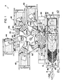
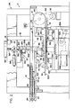
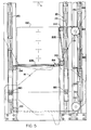
- Figures 1 and 2 show a machine A for automatically cutting cigar wrappers from natural tobacco leaf B which uses a cutting and transierring device after the machine has located and placed leaf B in the proper position for cutting a wrapper therefrom.
- Machine A is illustrated as a total processing device of the type controlled by a programmable controller and/or digital computer in accordance with standard machine control practices.
- Machine A includes schematically represented preferred structures for accomplishing the positioning of the leaf for proper cutting at a cut position. A full description of the arrangement for locating the leaf in the proper position is disclosed in our above-mentioned application.
- Machine A includes a leaf spreader 10, a conveyor 12, a scanning mechanism 13 on a support bridge 15, a movable cutting table 14, an appropriate mechanism 20 for positioning the table with the leaf in the proper cutting position, and a cutting and transferring device comprising a cutting mechanism 22 supported on bridge 24 and a transfer element 30.
- storage spool or bobbin loaders 40, 42, 44 and 46 are positioned around transfer element 30 at appropriate locations to remove cut and transferred cigar wrappers onto appropriate spools for subsequent use in a machine for winding the wrappers around the body of a cigar.
- each storage spool or bobbin loader so that a wrapper from a selected location on transfer element 30 will be removed from element 30 and transferred to the appropriate bobbin loader 40-46 for subsequent of the wrapper.
- leaf B is fed into the machine A and cut wrappers are removed from the transfer element 30 and placed onto bobbin loaders 4o-46.
- spreader 10 is somewhat standard and includes a plurality of angularly driven belts 60 positioned above and below the plane at which a leaf B is manually fed into machine A.
- Drive belts 62, 64 drive the angularly disposed belts 60 to spread leaf B in accordance with standard technology for handling tobacco leaves.
- Rolls 65, 67 drive the lower angularly disposed belts 60. Similar rolls are provided for driving the upper belts.
- conveyor 12 which, in the illustrated embodiment, includes a flat, transparent, perforated belt 70 driven along a primary vacuum chamber 72 at the upper run of the belt and a secondary vacuum chamber 80 at the lower run of the belt.
- Cylinders 82, 84 are adapted to move the secondary vacuum chamber 80 in a downward direction to transfer a leaf on belt 70 to the cutting table 14 for subsequent movement into the cutting position in alignment with mechanism 22.
- a valve conduit 86 communicates the primary and secondary vacuum chambers so that the vacuum may be diminished in chamber 80 during transfer of a leaf B from belt 70 onto the cutting table 14.
- a standard vacuum drive roll 90 maintains the vacuum on belt 70 to hold the leaf B in its spread condition as the belt carries the leaf from the upper run to the lower run.
- Belt 70 is driven by roll 90 through an appropriate motor 92 by a chain 94.
- Guide rolls 100, 102, 104 are adjusted to maintain tension in the perforated, transparent belt 70 as it moves along the path illustrated in FIGURE 2.
- the spread leaf on belt 70 passes over roll 90 to the lower run where it is held against the belt by the vacuum in secondary chamber 80.
- scanner 13 When in the proper position over cutting table 14 with the cutting table in the position shown in FIGURE 1, the secondary chamber is physically moved downwardly by cylinders 82, 84, at which time vacuum is released from the secondary chamber and vacuum applied to table 14 captures the spread leaf in a specific location determined by the position of the cutting table at transfer.
- scanner 13 includes a transversely extending> light source 110 within primary vacuum chamber 72 for shining a light through transparent belt 70.
- An appropriate light sensitive scanning head 112 determines the profile and defects in leaf B being scanned. These defects determine the various orientation of table 14 at the cutting position to obtain useable wrappers during the cutting process.
- the present invention does not relate to this aspect for orienting the leaf at the cutting position and this operation could be done in various ways.
- the scanning or sensing mechanism 13 involves an arrangement for automatically determining the proper orientation of cutting table 14 with respect to cutting position of mechanism 22 during subsequent cutting operations which employ the preferred embodiment of the present invention.
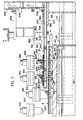
- Table 14 is a flat relatively lightweight structure best shown in FIGURES 3-7 and 9.
- Table 14 includes a flat body portion 120.formed from aluminum and having an upper cutting plate 122 defining an upwardly facing, flat cutting surface 123 and formed from rigid nylon or another appropriate rigid cutting material.
- Surface 123 is provided with a number of closely spaced vacuum directing perforations 124 which communicate with vacuum passages 126 in body portion 120 to communicate the surface 123 with the network of vacuum passages 126.
- These passages are in turn connected to a vacuum conduit 128 so that vacuum can be selectively directed to surface 123 to hold a spread leaf onto this surface after it has been transferred from belt 70. Vacuum in passages 126 can be released to remove a spent leaf after cutting.
- Table 14 is lightweight and relatively thin. It is slidably mounted on an upper flat surface of a lower anvil 130 which supports cutting table 14 during its sliding and shifting movement in machine A. This anvil also provides the reaction force member for the cutting operation. Thus, cutting table 14 need not have the structural strength to withstand the cutting forces, but need only carry the leaf to the proper oriented cutting position with respect to cutting mechanism 22. Although a specific structure has been shown for cutting table 14, other structures could be used.
- any number of arrangements could be used for moving table 14 to the proper cutting position determined by the scanning operation.
- the scanning operation determines the cut position by a computer process which is used to control the moving mechanism 20 to position the leaf on surface 123 in the proper orientation for subsequent cutting.
- three generally parallel binary controlled motors 15Q,152 and 154 are illustrated.
- appropriate binary information is provided to the three binary motors which are then shifted into a position to locate leaf B in the proper orientation for cutting by mechanism 22.
- Each of the binary motors has essentially the same structure; therefore, only motor 154, best shown in FIGURE 4, will-be described in detail. This description applies equally to the other two binary motors.
- Cylinders 160, 162 and 164 are sized to provide movement in accordance with a binary relationship. Thus, each of the cylinders provides a different amount of movement. This is all standard practice and clearly illustrated in the previous application.
- Guide rods 170 for each of the motors maintain the motors in alignment and also guide the movement of the output element 172, as best shown in FIGURE 4.
- Motors 150, 152 and 154 thus, move upstanding pins 180, 182 and 184, respectively, in accordance with the amount of movement of output element 172 of each of the motors.
- These upstanding pins engage the undersurface of table 14 in grooves 190, 192. and 194. As is clearly illustrated, the height of pins 180, 182 and 184 is less than the depth of the groove.
- the pins receive no vertical component of force and serve only to slide table 14 along the upper surface of anvjl 130.
- Grooves 190, 192 are generally aligned and extend transversely across table 14.
- Groove 194 extends perpendicular to the other grooves and extends longitudinally with respect to table 14.
- Output elements 172 control the movement of drive plates 200, which actually drive the pins.
- Pins 180 and 182 are each supported on a drive plate 200.
- Pin 184 is driven by a chain 202 having a coupling 204 for joining the chain with the drive plate 200 of motor 154, as best shown in FIGURE 4.
- Chain 202 drives pin 184 in a groove extending laterally across anvil 130, as best shown in FIGURE 3.
- sprockets 210-215 are positioned in a manner, best shown in FIGURE 5, to drive pin 184 in accordance with the movement of output element 172 controlled by motor 154.
- the relationship of the grooves in table 14 and the movement of the pins with respect to these grooves in response to the amount of output movement from binary motors 150-154 determines the actual orientation of table 14 during the cutting operation.
- the scanning mechanism 13 for locating the proper cuts to be made in leaf B controls the amount of subsequent movement of the pins 180-184 to locate cutting table 14 in the proper position for cutting a leaf B held onto upwardly facing cutting surface - 123.
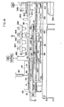
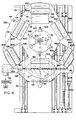
- cutting mechanism 22 includes four separate and distinct cutting heads 300, 302, 304 and 306. These heads are used for cutting separate cigar wrappers or profiles P from opposite sides of tobacco leaf B. In the illustrated embodiment, two of the heads are used for each half of the leaf. They have different sizes so that they can cut different types of cigar wrappers from each half of the leaf. The mechanism would operate with a single cutter, with a single cutter for each half of the leaf, or with two or more cutters for each half of the leaf. In practice, each of the cutting heads is for a different shape or leaf half and is deposited subsequently onto one of the four bobbin loaders or storage spool mechanisms 40-46 shown in FIGURE 1.
- a driving system including an upper pancake cylinder 310, best shown in FIGURE 2.
- This cylinder receives pneumatic pressure to control the cutting force of cutting heads 300-306.
- Rod 312 of cylinder 310 is conneted to the upper one of two toggle links 314, 316 which are operable by reciprocation by an appropriate hydraulic cylinder 318.
- a cutting and/or transfer operation is accomplished at the bottom dead center of the toggle links 314, 316.
- both a cut and a transfer is accomplished by toggle links 314, 316.
- a common, pivoted power or drive plate 320 is oscillated by toggle links 314, 316 to control the downward movement of one of four drive rods 322, each of which is used to control the movement of one of the cutting heads 300, 302, 304 and 306.
- Each drive rod 322 includes a top cam surface 324 and an intermediate pin 326 which extends diametrically through the rod.
- Rods 322 are reciprocated in vertical directions by appropriate rod guides 328, one of which reciprocally mounts each of the drive rods 322.
- the axis of movement of rod 322 determines the cut position for each of the cutting heads, as will be apparent later.
- the cut position is also the transfer position for each of the cutting heads so that the axis of each of the four rods 322 determines the cut-transfer position for each of the wrappers cut from leaf B by one of the cutting heads.
- drive mechanism 22 includes an interposer or roller 320 for each of the rods 322 of the cutting heads or cutters 300-306.
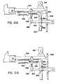
- roller 320 For select one of the cutters to perform a cutting operation during a downward movement of power plate 320, one of the rollers 330 is shifted into the position shown in FIGURE 10A by an appropriate power cylinder 332. Since only one wrapper is cut for each downward cycle of cutting mechanism 22, only one of the four rollers 330 is used at any given time.
- the selected roller engages its drive rod 322 to activate one of the cutting heads 300-306 for the cutting operation of a wrapper P from leaf B supported on table 14.
- a selected one of the cutting heads 300-306 is actuated by interposing roller 330 between plate 320 and cam portion 324 (if a cut is to be performed).
- the other cutting heads are moved downwardly by individual links 334 for controlling each of the other non- selected drive rods 322.
- a cut can be made by each downward movement of cutting mechanism 22 and a transfer of a cigar wrapper or profile can also be made by a cutting head not then being used for cutting.
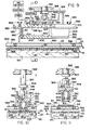
- each of the heads 300-306 details of each of the heads 300-306 are illustrated.
- only cutting head 304 will be described in detail. This description will apply equally to the other cutting heads.
- a single cutting head can be used or a plurality of cutting heads with some located on one side of the,stem in leaf B and the other located on the opposite side of the stem. If the wrapper sizes desired are the same, only two cutting heads would be employed, one for each side of leaf B. Since the desired shape of the profile or cigar wrapper may be different, two separate cutters for each side of the leaf are illustrated. This is to show that the device is well adapted for a versatile cigar wrapper processing machine, as shown in FIGURES 1 and 2.
- Cutting head 304 includes a housing 340 supported on a threaded shank 342 at the downward end of rod 322 for controlling the vertical position of this particular cutter.
- An adjustable stop collar 344 is threadably received on shank 342 and is adjusted in a vertical direction on the shank ⁇ to-limit the upward movement of cutting head 304, as shown in FIGURES 9, 11 and 13.
- Mounting hub 346 joins housing 340 with shank 342 by an appropriate bolt 347.
- a downwardly extending guide pin 348 supported on frame 324, which also reciprocally mounts link 334 and provides the support for the various guide sleeves 328 of cutters 300-306.
- An aligning bracket 350 extends from hub 346 to guide pin 348 for guiding cutter 304 in a vertical direction during the cutting operation and the transferring operation.
- An inlet coupling 360 includes a vacuum tube 362 and a pressure or atmosphere tube 364. When pressure is applied through tube 364, this overrides any vacuum in line 362 to provide a positive pressure within the plenum chamber of cutting head 304. Thus, by an appropriate valving arrangement either a vacuum or a positive pressure can be applied to the cutting head for a purpose to be described later.
- Opposed grooves 370 slidably receive cutting assembly 380 having outwardly extending flanges 382 which engage grooves 370 and allow transverse sliding engagement of the cutting assembly with housing 340.
- a plurality of set screws 384 extend through the housing and engage cutting assembly 380 to hold the cutting assembly in a position which is determined by engagement of end 383 with stop 385, as shown in FIGURE 9.
- a port 386 in the upper portion of assembly 380 communicates coupling 360 with the interior of the cutting assembly which includes a cutting blade 390 with a downwardly extending cutting edge 392 circumscribing a desired shape for a cigar wrapper to be cut. As can be seen, edge 392 is in a single plane which is parallel to the cutting surface 123 of cutting table 14.
- a profile or wrapper capturing element 400 having a downwardly facing flat surface 402 and a plurality of apertures 404 closely spaced around the periphery of element 400 which generally matches the shape of the wrapper to be cut.
- These apertures 404 which are spaced by a distance not exceeding approximately one-fourth inch are communicated with an internal plenum chamber 406 communicated with port 386 and pressure controlling coupling 360.
- vacuum is directed to tube 362 vacuum is applied at the various apertures 404 for holding a cut cigar wrapper or profile onto downwardly facing holding surface 402 of profile or leaf capturing element 400.
- Surface 402 is parallel to cutting surface 123 of table 14, as best shown in FIGURE 9.
- An appropriate biasing means shown as a thin strip of sponge rubber or plastic, extending around blade 390 biases capturing element 400 outwardly from edge 392 a distance Z.
- This biasing means is adhesively secured to the upper surface of element 400 and surface 412 of cutting assembly 380.
- the biasing strip defines the inner plenum chamber 406, sup - ports the capturing element 400 and also controls the biasing action of this element in a direction vertically downward toward the cutting surface 123.
- a vacuum can be applied to chamber 406 to hold a cut leaf or profile onto surface 402.
- a positive pressure can be applied to plenum chamber 406 to facilitate the release and transfer actions.
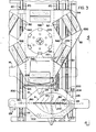
- transfer element 30 includes an indexing table which indexes through an angle r between each cutting and transferring cycle of machine A.
- the indexing action is about an axis x which is orthogonal to cutting surface 123 of table 14.
- a plurality of switch cams 402 are positioned at the indexed positions labeled I-VI in FIGURE 6. These switch cams indicate which section of the transfer element is positioned at the cut and transfer position at any given time.
- Table 500 includes a central hub 504 concentric with index axis x communicated with a vacuum conduit 506, best shown in FIGURE 7. This conduit is supported onto fixed frame 508 which also supports the switches 510, 512 having switch arms 510a, 512a, respectively. These switches indicate which station is positioned adjacent the cutting operation defined by the general position of cutting mechanism 22 for use in controlling sequencing of machine A.
- a Ferguson indexing mechanism 520 is used for indexing table 500 repeatedly through angle r by a continuously driven motor 524 and an intermittently actuated clutch 522. This is shown in FIGURE 2.
- Synchronizing device 526 can be used to indicate the indexing operation of mechanism 520 for timing the operation of elements on machine A. Other arrangements could be used for indexing table 500 between the various angular positions to perform the operation of the preferred embodiment of the present invention.
- each of these patterns has subpatterns ma, mb and na, nb which are circular and concentric with axis x.
- the patterns are aligned with the cut positions of the various cutting heads 300, 302, 304 and 306.
- the patterns or paths of movement of the elements on table 500 are concentric and intersect the particular locations of the cutting heads used for processing a particular type of cut. For instance, a large wrapper on one side of leaf B would be processed by elements on table 500 and moving along path mb. Small wrappers from this same side of the leaf would be processed by elements located on path ma.
- the large wrappers are processed in accordance with elements located on path na whereas small wrappers are processed on elements located on path nb.
- a single path could be used if a single cutter were used.
- Two paths m and n would be used if one type of cut is to be made in each of the two leaf halves.
- the number of paths in the preferred embodiment are dictated by the number of cutters and their relative positions with respect to each other. This is true because the cutting takes place at a position determined by the position of the cutter. This dictates the position of the transfer of a profile P onto table 500 and subsequent removal of the wrapper from the table in an oriented manner determined by its position of the cut and transferred wrapper on the element 30.
- table 500 includes clearance or cut-away portions 530 of table 500 at positions II, IV and VI. These cut-away portions are in path m which in practice includes two separate subpaths ma, mb. To reduce the weight of table 500 these cut-away portions are defined by a chord cut across the periphery of table 500 at a position close as possible to the adjacent path or pattern n. Thus, the table has a reduced weight caused by the missing portions of table 500, which portions create and are the three spaced clearance or cut-away portions 530. Intermediate cut-away or clearance portions 530 there are provided profile or cigar wrapper receiving portions 532 at positions I, III and V.
- path m there is first a cut-away or clearance portion 530 and then a profile or wrapper transfer portion 532.
- the clearance portions are shaped to diminish as much as possible the size of table 500 without affecting its static and dynamic balance and its capacity to support the transfer action of a wrapper.
- path n there are also provided alternate clearance or cut-away portions 540 and profile or wrapper receiving portions 542 spaced from each other the rotary indexing distance r.
- the cut-away or clearance portions are actual openings 540 within table 500.
- the use of two patterns m, n provide a cut-away portion or clearance portion and a transfer portion at the position of mechanism 22 after each index.
- both a cut and a transfer operation for a wrapper can be made at each indexed location of table 500.
- the table is indexed by mechanism 520 to a given position which will locate a clearance portion of table 500 between two cutting heads and surface 123 of table 14 and a transfer portion of table 500 below the other two cutting heads. This process alternates as table 500 is indexed.
- each cutter is first aligned with a clearance portion and then with a transfer portion on table 500 forming the basic structure of transfer element 30.
- table 500 is formed from an upper aluminum sheet 560 which is about 0.03 to 0.040 inches in thickness and a lower similar sheet 562. These sheets are separated by a honeycomb core 564 to import cantilever rigidity to sheets 560, 562.
- the honeycomb is preferably formed from cardboard. In some instances, the honeycomb can be formed from aluminum foil with a thickness of .003-.005 inch.
- Edge strips 566 extend around the peripheral edge of table 500 and strips 568 are positioned around the periphery of the cut-away or clearance portions 540.
- the table is a relatively lightweight structure which is supported by an upper ring 570 and a lower support ring 572. Ring 570 is used to mount switch cams 502 at the various indexed positions of table 500. Consequently, the switch cams are not supported directly on the structure forming table 500 but on the supporting structure therefor.
- Table 500 includes an appropriate internal vacuum passage network 580, best shown in FIGURES 7 and 8. This internal vacuum network is communicated with vacuum conduit 506 through center hub 504. Any appropriate vacuum network can be provided for directing a negative pressure to the various profile receiving portions on table 500.
- Each profile receiving portion 532, 542 includes essentially the same structure having two wrapper holding elements 600, 602, one for each of the two cutting heads for a leaf half. Each of these holding elements is substantially the same, except for the difference in the shape of the wrapper being held. Consequently, only holding element 602 will be described in detail. This description will apply equally to holding element 600 as shown in FIGURE 6.
- wrapper or profile holding element 602 includes an upper flat plastic, rigid plate 610 defining a generally flat holding surface 612 parallel with cutting edge 392 of the cutter 304, or the cutting edge of any other cutter.
- a plurality of closely spaced apertures 614 are spaced along-the periphery of a profile to be cut and generally interior of this periphery.
- FIGURE 8 This is shown in FIGURE 8 wherein the periphery is illustrated in phantom line and the pattern for apertures 614 is within this circumscribed shape.
- a peripherally extending spacer plate 616 is positioned between flat plate 610 and the upper surface of table 500 and is held thereon by a plurality of spaced bolts 618.
- This spacer plate has an internal opening shown in dashed lines in FIGURE 8 and defining an internal plenum chamber 620 communicated with the various apertures 614 of flat plate 610.
- Three relatively large apertures 622 are provided in upper sheet 560 of table 500 to intersect plenum chamber 620. These holes form a valving device for each holding element. The total area of holes 622 is substantially less than the total area of the apertures 614 at a given holding element.
- Position I of table 500 is at the cutting or cut position of cutter 304 determined by the axis of reciprocal rod 322, clearance portion 540 is over leaf B at the cut position.
- the cycle of the cutting mechanism 22 is preceded by interposing the roller 330 above the rod 322 of cutter 304.
- this one rod 322 is forced downwardly to force cutter 304 into cutting engagement with oriented leaf B as shown in FIGURE 10.
- the cutting head extends through table 500 at the aligned clearance portion 540.
- the table can be indexed to the next position where a profile holding element, in this instance element 602, of the profile receiving portion 542 of, position II is aligned with the cut position determined by rod 322 of cutting head 304.
- This position is shown in FIGURES 12 and 13.
- cutting head 304 is moved downwardly a transfer distance less than the cutting distance and corresponding to a transfer position as shown in FIGURE 12.
- the biasing strip 410 forces element 400 against surface 312 with a light force caused by the sponge rubber or strip 410.
- Vacuum within network 58Q is combined with positive pressure in tube 364 of coupling 360 to positively transfer the cut profile from surface 402 to surface 612. This is shown in FIGURE 12.
- FIGURES 10A and 12A are used only to disclose a selecting arrangement for determining whether a rod 322 is performing a cutting stroke or a transfer depositing stroke. Of course, if there is no wrapper captured on surface 402 downward movement of rod 322 of a given cutting head will have no effect and is only an idling action.
- selector roller 330 has selected cutting head 302 for the cutting operation. This cutting head then moves within clearance portion 530 of path or pattern m for cutting a wrapper P from leaf B supported on surface 123. At the same time, and during the same downward movement of power plate 320, all other cutting heads are moved downwardly a transfer distance determined by the links 334 of the other cutting heads. Since cutter or cutting head 304 was used in the previous cutting operation, it contains a captured leaf B which is deposited onto holding element 602 of profile receiving portion 542 on table 500. The other cutting head 306 was not selected for a cut prior to the indexed position shown in FIGURE 7.
- FIGURE 7 the cutting head 300 idles in a noncutting position as shown. No transfer can be done by this head in this position because it has no wrapper and is not over or on the wrapper receiving portion on table 500.
- Vacuum unit 650 is used for withdrawing a spent leaf from cutting table 14 after the cutting operations have taken place and before the table is moved into the position for accepting the next leaf to be cut. A plurality of cuts can be taken from the leaf before it is spent and then with- drawn by unit 650.
- the unloading devices 50 each have a forward portion aligned with a subpattern ma, mb, na or nb and an extended portion aligned with one of the bobbin wrapper receiving units 40-46. Consequently at each indexed ! position of table 500, one of the unloading devices is in position over table 500 to remove a cut wrapper.
- the unloading device 50 for each cutting head 300-306 is indi- cated in parentheses. At the illustrated indexed position, no wrapper is in position to be removed. In the next index position, the unloading device aligned with a transferred cut wrap- per will be actuated to remove the cut wrapper or wrappers from table 500.
- Cylinder 310 controls the downward cutting force and the cutting position is generally dictated by the reaction of the cutting action against this cylinder.
Landscapes
- Manufacturing Of Cigar And Cigarette Tobacco (AREA)
- Manufacture Of Tobacco Products (AREA)
Applications Claiming Priority (2)
| Application Number | Priority Date | Filing Date | Title |
|---|---|---|---|
| US4187379A | 1979-05-23 | 1979-05-23 | |
| US41873 | 2002-01-07 |
Publications (2)
| Publication Number | Publication Date |
|---|---|
| EP0020003A2 true EP0020003A2 (fr) | 1980-12-10 |
| EP0020003A3 EP0020003A3 (fr) | 1981-09-30 |
Family
ID=21918799
Family Applications (1)
| Application Number | Title | Priority Date | Filing Date |
|---|---|---|---|
| EP80301190A Withdrawn EP0020003A3 (fr) | 1979-05-23 | 1980-04-15 | Procédé et dispositif pour découper et transférer le profil d'une feuille de tabac ayant un contour déterminé |
Country Status (1)
| Country | Link |
|---|---|
| EP (1) | EP0020003A3 (fr) |
Cited By (2)
| Publication number | Priority date | Publication date | Assignee | Title |
|---|---|---|---|---|
| EP0036056A1 (fr) * | 1980-03-13 | 1981-09-23 | GULF & WESTERN CORPORATION | Appareil de transport pour des feuilles naturelles de tabac |
| CN116058525A (zh) * | 2023-02-14 | 2023-05-05 | 红云红河烟草(集团)有限责任公司 | 打叶复烤设备出片率和叶片结构控制的表征方法 |
Family Cites Families (3)
| Publication number | Priority date | Publication date | Assignee | Title |
|---|---|---|---|---|
| DE126170C (fr) * | ||||
| US3542038A (en) * | 1969-01-10 | 1970-11-24 | American Mach & Foundry | Cigar manufacture |
| EP0031318A1 (fr) * | 1978-03-09 | 1981-07-01 | GULF & WESTERN CORPORATION | Appareil pour découper un élément d'une feuille naturelle de tabac |
-
1980
- 1980-04-15 EP EP80301190A patent/EP0020003A3/fr not_active Withdrawn
Cited By (2)
| Publication number | Priority date | Publication date | Assignee | Title |
|---|---|---|---|---|
| EP0036056A1 (fr) * | 1980-03-13 | 1981-09-23 | GULF & WESTERN CORPORATION | Appareil de transport pour des feuilles naturelles de tabac |
| CN116058525A (zh) * | 2023-02-14 | 2023-05-05 | 红云红河烟草(集团)有限责任公司 | 打叶复烤设备出片率和叶片结构控制的表征方法 |
Also Published As
| Publication number | Publication date |
|---|---|
| EP0020003A3 (fr) | 1981-09-30 |
Similar Documents
| Publication | Publication Date | Title |
|---|---|---|
| US6349241B1 (en) | Method and apparatus for automatically laying, cutting and removing material on and from a continuously moving conveyor | |
| US3478397A (en) | Brick cutter and hacker | |
| RU1837818C (ru) | Устройство дл получени деталей одежды, выкраиваемых из полотна материала | |
| CN109514230A (zh) | 一种手动剃须刀全自动组装设备及其控制方法 | |
| CN108436198A (zh) | 一种气缸端盖攻牙加工自动线 | |
| EP0020003A2 (fr) | Procédé et dispositif pour découper et transférer le profil d'une feuille de tabac ayant un contour déterminé | |
| AU769047B2 (en) | Device for producing and withdrawing stacks of plastic bags, especially bags for automatic machines | |
| AU557447B2 (en) | Apparatus and method for processing and transferring battery cell elements | |
| US4231558A (en) | Apparatus for accumulating articles such as bags | |
| US3933063A (en) | Turret roll slitting machine | |
| US4915368A (en) | Method of and apparatus for arranging sheets | |
| CN115583500A (zh) | 塑料托盘码垛生产线及其剪料机械手臂 | |
| US6213011B1 (en) | Loading and offloading systems for printing machine | |
| US3916600A (en) | Device for loading of packages into transport containers | |
| US4173275A (en) | Device for assembling a plurality of large panel layers into a press pack | |
| US4323149A (en) | Transfer apparatus for natural tobacco leaves | |
| EP0031318A1 (fr) | Appareil pour découper un élément d'une feuille naturelle de tabac | |
| CN210110526U (zh) | 一种屏蔽电感α绕线方式的全自动绕线机 | |
| CN113305462A (zh) | 钢模板自动化焊接生产线 | |
| CN212101203U (zh) | 一种竹篾自动上料装置 | |
| US6217276B1 (en) | Device for nesting taco shells | |
| CN217671188U (zh) | 滤膜进料单元 | |
| CN208304074U (zh) | 一种气缸端盖攻牙加工自动线 | |
| US4607995A (en) | Stacking and collecting apparatus | |
| GB2092091A (en) | Apparatus for stacking elongate elements such as sections or bars |
Legal Events
| Date | Code | Title | Description |
|---|---|---|---|
| PUAI | Public reference made under article 153(3) epc to a published international application that has entered the european phase |
Free format text: ORIGINAL CODE: 0009012 |
|
| AK | Designated contracting states |
Designated state(s): BE DE FR GB NL |
|
| PUAL | Search report despatched |
Free format text: ORIGINAL CODE: 0009013 |
|
| AK | Designated contracting states |
Designated state(s): BE DE FR GB NL |
|
| 17P | Request for examination filed |
Effective date: 19811020 |
|
| STAA | Information on the status of an ep patent application or granted ep patent |
Free format text: STATUS: THE APPLICATION IS DEEMED TO BE WITHDRAWN |
|
| 18D | Application deemed to be withdrawn |
Effective date: 19830504 |
|
| ITCP | It: supplementary protection certificate |
Spc suppl protection certif: CCP 480 |
|
| RIN1 | Information on inventor provided before grant (corrected) |
Inventor name: LOGAN, DAVID JOPSON Inventor name: WOOD, KENNETH OTTIWELL |