EP0019495B1 - Dispositif d'affichage pour tableau de bord d'un véhicule automobile - Google Patents
Dispositif d'affichage pour tableau de bord d'un véhicule automobile Download PDFInfo
- Publication number
- EP0019495B1 EP0019495B1 EP80400382A EP80400382A EP0019495B1 EP 0019495 B1 EP0019495 B1 EP 0019495B1 EP 80400382 A EP80400382 A EP 80400382A EP 80400382 A EP80400382 A EP 80400382A EP 0019495 B1 EP0019495 B1 EP 0019495B1
- Authority
- EP
- European Patent Office
- Prior art keywords
- conductors
- conductor
- state
- light
- display device
- Prior art date
- Legal status (The legal status is an assumption and is not a legal conclusion. Google has not performed a legal analysis and makes no representation as to the accuracy of the status listed.)
- Expired
Links
- 239000004020 conductor Substances 0.000 claims description 64
- 230000011664 signaling Effects 0.000 description 1
Images
Classifications
-
- B—PERFORMING OPERATIONS; TRANSPORTING
- B60—VEHICLES IN GENERAL
- B60Q—ARRANGEMENT OF SIGNALLING OR LIGHTING DEVICES, THE MOUNTING OR SUPPORTING THEREOF OR CIRCUITS THEREFOR, FOR VEHICLES IN GENERAL
- B60Q3/00—Arrangement of lighting devices for vehicle interiors; Lighting devices specially adapted for vehicle interiors
- B60Q3/10—Arrangement of lighting devices for vehicle interiors; Lighting devices specially adapted for vehicle interiors for dashboards
- B60Q3/16—Circuits; Control arrangements
-
- H—ELECTRICITY
- H05—ELECTRIC TECHNIQUES NOT OTHERWISE PROVIDED FOR
- H05B—ELECTRIC HEATING; ELECTRIC LIGHT SOURCES NOT OTHERWISE PROVIDED FOR; CIRCUIT ARRANGEMENTS FOR ELECTRIC LIGHT SOURCES, IN GENERAL
- H05B44/00—Circuit arrangements for operating electroluminescent light sources
-
- G—PHYSICS
- G09—EDUCATION; CRYPTOGRAPHY; DISPLAY; ADVERTISING; SEALS
- G09F—DISPLAYING; ADVERTISING; SIGNS; LABELS OR NAME-PLATES; SEALS
- G09F13/00—Illuminated signs; Luminous advertising
- G09F13/20—Illuminated signs; Luminous advertising with luminescent surfaces or parts
- G09F13/22—Illuminated signs; Luminous advertising with luminescent surfaces or parts electroluminescent
- G09F2013/227—Electroluminescent displays for vehicles
-
- Y—GENERAL TAGGING OF NEW TECHNOLOGICAL DEVELOPMENTS; GENERAL TAGGING OF CROSS-SECTIONAL TECHNOLOGIES SPANNING OVER SEVERAL SECTIONS OF THE IPC; TECHNICAL SUBJECTS COVERED BY FORMER USPC CROSS-REFERENCE ART COLLECTIONS [XRACs] AND DIGESTS
- Y02—TECHNOLOGIES OR APPLICATIONS FOR MITIGATION OR ADAPTATION AGAINST CLIMATE CHANGE
- Y02B—CLIMATE CHANGE MITIGATION TECHNOLOGIES RELATED TO BUILDINGS, e.g. HOUSING, HOUSE APPLIANCES OR RELATED END-USER APPLICATIONS
- Y02B20/00—Energy efficient lighting technologies, e.g. halogen lamps or gas discharge lamps
- Y02B20/30—Semiconductor lamps, e.g. solid state lamps [SSL] light emitting diodes [LED] or organic LED [OLED]
Definitions
- the present invention due to the collaboration of Mr. Jean-Claude COSTE, relates to improvements in the display of information on the vehicle dashboard.
- the present invention makes it possible to remedy this state of affairs by the fact that it recommends a means of supplying n (n - 1) light-emitting diodes with only n conductors, n being any whole number other than zero.
- the display device for example for the dashboard of a motor vehicle which is of the type comprising indicator lights such as, for example, light-emitting diodes and supply conductors, is remarkably unable in that it comprises: n supply conductors in parallel, n being any whole number at least equal to two, between which, these conductors being taken two by two, are connected head to tail two light-emitting diodes in parallel, and means for supplying each of the conductors at 3 different voltages, namely: high state, low state and high impedance state.
- the means for supplying each of the conductors, at three different voltages comprise, for each conductor, the connection in series between a source of positive voltage and the ground: of a resistance and of the collector space -emitter of two successive transistors whose common point is connected to the conductor to be supplied and whose bases are each connected to a variable control voltage source via a resistor in series.
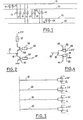
- the conductors 10, 20, 30, 40 can be supplied with three-state control signals, namely: high state, low state and high impedance state, to control a light-emitting diode, a line in the high state, a line in the low state and two lines with high impedance.
- three-state control signals namely: high state, low state and high impedance state
- the line 10 is in the high state
- the line 20 in the low state and the lines 30 and 40 in the high impedance state the light-emitting diode 12 is lit and all the others are off.
- FIG. 2 illustrates a first means of producing a three-state line, for example on the conductor 10 in FIG. 1.
- a circuit is produced, between the most 5 volts and the ground, successively comprising: a resistor 51, the collector-emitter space of a first transistor 54, a junction point 15 with the conductor 10 and the collector-emitter space of a second transistor 55.
- the base of the first transistor 54 is connected to a variable control voltage source 56 via a resistor 52 and the base of the second transistor 55 is also connected to a second variable voltage source 57 via a resistor 53.
- the presence of the resistor 51 aims to limit the value of the current in the light-emitting diodes to a value that they can withstand.
- Resistors 52 and 53 similarly limit the value of the current on the basis of transistors 54 and 55.
- Each of the conductors 10, 20 30 40 of FIG. 1 being equipped with a circuit such as that illustrated in FIG. 2, by driving the respective voltages 56 and 57 using an appropriate logic circuit, it can be seen that a means has been revealed for putting each of said conductors in the desired state, chosen from the three states: high state, low state and high impedance state and that as a result we are able to make the one that we desire light the twelve light-emitting diodes of FIG. 1, only by acting on the state of the conductors 10, 20, 30 and 40.
- FIG. 3 illustrates a second embodiment which is a preferred mode and according to which the transistors of FIG. 2 are replaced by "three-state" adapters, for example amplifier circuits of the type 74 125 in the TEXAS INSTRUMENTS catalog.
- FIG. 4 illustrates, in an enlarged manner, the detail of the supply circuit associated, for example, with the conductor 10. It can be seen that two "three-state" adapters 60 and 61 replace the two transistors 54 and 55 of FIG. 2.
- FIG. 3 represents all of the conductors - 10, 20, 30, 40 for supplying light-emitting diodes and the associated supply circuits each have two doors with three states.
- the current which passes through the light-emitting diode, which it is desired to light up is of the order of 22 mA.
Landscapes
- Engineering & Computer Science (AREA)
- Mechanical Engineering (AREA)
- Physics & Mathematics (AREA)
- Microelectronics & Electronic Packaging (AREA)
- Optics & Photonics (AREA)
- Control Of El Displays (AREA)
- Control Of Indicators Other Than Cathode Ray Tubes (AREA)
- Instrument Panels (AREA)
- Illuminated Signs And Luminous Advertising (AREA)
Applications Claiming Priority (2)
| Application Number | Priority Date | Filing Date | Title |
|---|---|---|---|
| FR7912073 | 1979-05-11 | ||
| FR7912073A FR2456359A1 (fr) | 1979-05-11 | 1979-05-11 | Dispositif d'affichage pour tableau de bord d'un vehicule automobile |
Publications (2)
| Publication Number | Publication Date |
|---|---|
| EP0019495A1 EP0019495A1 (fr) | 1980-11-26 |
| EP0019495B1 true EP0019495B1 (fr) | 1981-11-04 |
Family
ID=9225378
Family Applications (1)
| Application Number | Title | Priority Date | Filing Date |
|---|---|---|---|
| EP80400382A Expired EP0019495B1 (fr) | 1979-05-11 | 1980-03-21 | Dispositif d'affichage pour tableau de bord d'un véhicule automobile |
Country Status (4)
| Country | Link |
|---|---|
| US (1) | US4323895A (online.php) |
| EP (1) | EP0019495B1 (online.php) |
| DE (1) | DE3060069D1 (online.php) |
| FR (1) | FR2456359A1 (online.php) |
Cited By (1)
| Publication number | Priority date | Publication date | Assignee | Title |
|---|---|---|---|---|
| CN105764183A (zh) * | 2016-03-14 | 2016-07-13 | 安徽康佳绿色照明技术有限公司 | 一种兼容高低压的led供电系统 |
Families Citing this family (12)
| Publication number | Priority date | Publication date | Assignee | Title |
|---|---|---|---|---|
| GB2098736B (en) * | 1981-04-22 | 1985-06-05 | Ae Plc | Change-gear indicator |
| EP0104848B1 (en) * | 1982-09-18 | 1986-11-26 | Lillywhites Cantabrian Limited | Display unit |
| US4845489A (en) * | 1985-12-23 | 1989-07-04 | Chrysler Motors Corporation | Electroluminescent display drive circuitry |
| EP0242631A3 (de) * | 1986-03-27 | 1988-12-21 | Siemens Aktiengesellschaft | Analog anzeigendes Messinstrument mit zweifarbig lichtemittierenden Dioden |
| US5661645A (en) | 1996-06-27 | 1997-08-26 | Hochstein; Peter A. | Power supply for light emitting diode array |
| US6150771A (en) * | 1997-06-11 | 2000-11-21 | Precision Solar Controls Inc. | Circuit for interfacing between a conventional traffic signal conflict monitor and light emitting diodes replacing a conventional incandescent bulb in the signal |
| DE19857980C2 (de) * | 1998-12-16 | 2001-02-01 | Mannesmann Vdo Ag | Beleuchtbare Bedieneinheit einer Kraftfahrzeugklimaanlage |
| US20080191967A1 (en) * | 2007-02-12 | 2008-08-14 | Karl Spyros Papadantonakis | Passive display with planar interconnect |
| EP1995995A1 (en) * | 2007-05-25 | 2008-11-26 | 3Dconnexion Holding SA | Electric circuit for individually controlling light-emitting elements and optoelectronic device |
| US8358207B2 (en) * | 2009-05-29 | 2013-01-22 | GM Global Technology Operations LLC | System for pre-attentively communicating information to a driver of a vehicle |
| JP2017536670A (ja) * | 2014-11-20 | 2017-12-07 | コーニンクレッカ フィリップス エヌ ヴェKoninklijke Philips N.V. | 個別に指定可能なledモジュールを有するled装置 |
| US10772197B2 (en) * | 2018-04-24 | 2020-09-08 | Microsoft Technology Licensing, Llc | Electronically functional yarn |
Family Cites Families (2)
| Publication number | Priority date | Publication date | Assignee | Title |
|---|---|---|---|---|
| JPS5267522A (en) * | 1975-12-03 | 1977-06-04 | Hitachi Ltd | Display unit |
| DE2613647C3 (de) * | 1976-03-31 | 1981-08-27 | Licentia Patent-Verwaltungs-Gmbh, 6000 Frankfurt | Ansteuerschaltung |
-
1979
- 1979-05-11 FR FR7912073A patent/FR2456359A1/fr active Granted
-
1980
- 1980-03-21 DE DE8080400382T patent/DE3060069D1/de not_active Expired
- 1980-03-21 EP EP80400382A patent/EP0019495B1/fr not_active Expired
- 1980-04-24 US US06/143,489 patent/US4323895A/en not_active Expired - Lifetime
Cited By (1)
| Publication number | Priority date | Publication date | Assignee | Title |
|---|---|---|---|---|
| CN105764183A (zh) * | 2016-03-14 | 2016-07-13 | 安徽康佳绿色照明技术有限公司 | 一种兼容高低压的led供电系统 |
Also Published As
| Publication number | Publication date |
|---|---|
| FR2456359A1 (fr) | 1980-12-05 |
| US4323895A (en) | 1982-04-06 |
| DE3060069D1 (en) | 1982-01-14 |
| FR2456359B1 (online.php) | 1982-01-08 |
| EP0019495A1 (fr) | 1980-11-26 |
Similar Documents
| Publication | Publication Date | Title |
|---|---|---|
| EP0019495A1 (fr) | Dispositif d'affichage pour tableau de bord d'un véhicule automobile | |
| EP0464870B1 (en) | Absolute encoder of the multirotation type | |
| FR2494471A1 (fr) | Procede et dispositif pour la verification des fonctions d'un systeme indicateur recevant des donnees | |
| EP0318354B1 (fr) | Dispositif de transmission d'informations pour véhicule automobile et procédé de mise en oeuvre d'un tel dispositif | |
| ES2050588A2 (es) | Dispositivo de señalizacion de diagnostico muntifuncional para el salpicadero de un vehiculo. | |
| SE517414C2 (sv) | Anordning för övervakning av tvåtrådiga bussledare | |
| FR2541473A1 (fr) | Dispositif universel d'entrees-sorties | |
| EP0246132B1 (fr) | Circuit d'interface bidirectionnel présentant un accès unipolaire et un accés bipolaire pour des signaux logiques | |
| US3964012A (en) | Color display system in ultrasonic sonar | |
| FR2563026A1 (fr) | Dispositif de controle pour des amplificateurs d'attaque integres | |
| EP0340080B1 (fr) | Feu de signalisation à plusieurs fonctions, pour véhicule automobile | |
| US3665384A (en) | Road vehicle electrical system with transducers detecting faults and producing unique outputs operating a receiving and display unit | |
| EP1554810B1 (fr) | Codeur angulaire optique | |
| US4532472A (en) | LED level meter | |
| GB2230864A (en) | Combination meter system of vehicle | |
| FR2957559A1 (fr) | Dispositif de communitation pour haut de colonne de direction de vehicule automobile | |
| KR890004521Y1 (ko) | 회전기기의 속도 그라픽 표시장치 | |
| JPS6015227A (ja) | 車両におけるギヤポジシヨン表示装置 | |
| FR2584520A1 (fr) | Dispositif d'affichage comportant un reseau matriciel de sources lumineuses | |
| FR3153709A1 (fr) | Procédé de transmission de données | |
| EP0138709B1 (fr) | Contrôle du chargement de circuits intégrés du type registre série-parallèle ayant un registre de chargement distinct des étages de sortie | |
| JPS63308410A (ja) | 二端子網の光センサ | |
| EP0230406A1 (fr) | Dispositif de transmission simultanee de plusieurs signaux electriques entre deux enplacements | |
| FR2617617A1 (fr) | Dispositif electronique de commande d'un organe actionne par un moteur electrique | |
| JPH0131931Y2 (online.php) |
Legal Events
| Date | Code | Title | Description |
|---|---|---|---|
| PUAI | Public reference made under article 153(3) epc to a published international application that has entered the european phase |
Free format text: ORIGINAL CODE: 0009012 |
|
| AK | Designated contracting states |
Designated state(s): DE GB IT SE |
|
| 17P | Request for examination filed | ||
| ITCL | It: translation for ep claims filed |
Representative=s name: BARZANO' E ZANARDO ROMA S.P.A. |
|
| ITF | It: translation for a ep patent filed | ||
| GRAA | (expected) grant |
Free format text: ORIGINAL CODE: 0009210 |
|
| AK | Designated contracting states |
Designated state(s): DE GB IT SE |
|
| REF | Corresponds to: |
Ref document number: 3060069 Country of ref document: DE Date of ref document: 19820114 |
|
| PLBI | Opposition filed |
Free format text: ORIGINAL CODE: 0009260 |
|
| 26 | Opposition filed |
Opponent name: SIEMENS AG, BERLIN UND MUENCHEN Effective date: 19820804 |
|
| PGFP | Annual fee paid to national office [announced via postgrant information from national office to epo] |
Ref country code: DE Payment date: 19821209 Year of fee payment: 4 |
|
| PGFP | Annual fee paid to national office [announced via postgrant information from national office to epo] |
Ref country code: SE Payment date: 19830131 Year of fee payment: 4 |
|
| RDAG | Patent revoked |
Free format text: ORIGINAL CODE: 0009271 |
|
| STAA | Information on the status of an ep patent application or granted ep patent |
Free format text: STATUS: PATENT REVOKED |
|
| 27W | Patent revoked |
Effective date: 19831027 |
|
| GBPR | Gb: patent revoked under art. 102 of the ep convention designating the uk as contracting state | ||
| EUG | Se: european patent has lapsed |
Ref document number: 80400382.0 Effective date: 19850529 |