EP0019070A1 - Pneumatic tyre for a vehicle - Google Patents
Pneumatic tyre for a vehicle Download PDFInfo
- Publication number
- EP0019070A1 EP0019070A1 EP80101730A EP80101730A EP0019070A1 EP 0019070 A1 EP0019070 A1 EP 0019070A1 EP 80101730 A EP80101730 A EP 80101730A EP 80101730 A EP80101730 A EP 80101730A EP 0019070 A1 EP0019070 A1 EP 0019070A1
- Authority
- EP
- European Patent Office
- Prior art keywords
- tread
- edge
- rounded
- radii
- radius
- Prior art date
- Legal status (The legal status is an assumption and is not a legal conclusion. Google has not performed a legal analysis and makes no representation as to the accuracy of the status listed.)
- Granted
Links
Images
Classifications
-
- B—PERFORMING OPERATIONS; TRANSPORTING
- B60—VEHICLES IN GENERAL
- B60C—VEHICLE TYRES; TYRE INFLATION; TYRE CHANGING; CONNECTING VALVES TO INFLATABLE ELASTIC BODIES IN GENERAL; DEVICES OR ARRANGEMENTS RELATED TO TYRES
- B60C11/00—Tyre tread bands; Tread patterns; Anti-skid inserts
- B60C11/01—Shape of the shoulders between tread and sidewall, e.g. rounded, stepped or cantilevered
Definitions
- the invention relates to a pneumatic vehicle tire with a circumferential groove located in the area of the tire shoulder.
- the main task of the innovation is to give the tread zone in the area of the tire shoulder such a contour that the wear in the area of the tread edge becomes uniform.
- the lateral circumferential groove and the radially outward rounding of radii of approximately the same size are limited, while the tread edge is determined by a radius of curvature which is approximately three times as large as the aforementioned radii.
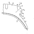
- the figure shows a partial cross section through a pneumatic vehicle tire for road vehicles, namely a shoulder zone of the tire.
- the tire body 1 which is made of rubber or rubber-like substances, has a carcass indicated by a dashed line 2 and above it in the area of the zenith of the tire a tread 3 which is delimited on both sides by an edge rib at 4, which thus also tread 5 to the side completes.
- the edge rib at 4 is limited laterally on the outside by a curve, for example in the order of 25 mm. This radius is designated R 1 . This rounding is followed by a further rounding, which is determined by the radius R 2 , which, however, is only about a third of the radius R 1 . This radius determines the upper edge of the circumferential groove 6, which in turn is grooved according to a radius R 3 , which has the size of R 2 . The tire merges from the groove 6 into the outer surface of the side wall 7.
- This design of the tire shoulder enables a comparatively soft deflection in the direction of arrow 8. A uniform abrasion is achieved.
Abstract
Description
Die Erfindung betrifft einen Fahrzeugluftreifen mit einer im Bereich der Reifenschulter befindlichen umlaufenden Nut.The invention relates to a pneumatic vehicle tire with a circumferential groove located in the area of the tire shoulder.
Bei bekannten Luftreifen dieser Art entsteht im Bereich der Laufflächenränder, also oberhalb der umlaufenden Nut eine ungleichmäßige Abnutzung des Laufstreifens.In known pneumatic tires of this type, uneven wear of the tread occurs in the area of the tread edges, that is to say above the circumferential groove.
Der Neuerung liegt im wesentlichen die Aufgabe zugrunde, der Laufstreifenzone im Bereich der Reifenschulter eine solche Kontur zu verleihen, daß die Abnutzung im Bereich des Laufflächenrandes gleichmäßig wird.The main task of the innovation is to give the tread zone in the area of the tire shoulder such a contour that the wear in the area of the tread edge becomes uniform.
Zur Lösung dieser Aufgabe sind gemäß der Neuerung die seitlich umlaufende Nut und die sich radial nach außen daran anschließende Rundung von Radien etwa gleicher Größe begrenzt, während der Laufflächenrand durch einen Krümmungsradius bestimmt ist, der etwa dreimal so.groß ist wie die vorgenannten Radien.To solve this problem, according to the innovation, the lateral circumferential groove and the radially outward rounding of radii of approximately the same size are limited, while the tread edge is determined by a radius of curvature which is approximately three times as large as the aforementioned radii.
Dadurch ergibt sich für den Laufflächenrand die Möglichkeit, vergleichsweise weich einzufedern, und zwar in der Weise, daß im Vergleich zu den übrigen Laufflächenzonen in bezug auf die Nachgiebigkeit keine wesentlichen Unterschiede mehr gegeben sind. Es wird auf diese Weise erreicht, daß im Bereich der meist am Laufflächenrand befindlichen Randrippe keine größere bzw. vorzeitige Abnutzung im Vergleich zu den übrigen Laufflächenpartien eintritt.This gives the tread edge the ability to deflect comparatively softly, in such a way that there are no significant differences in flexibility compared to the other tread zones. It is achieved in this way that in the area the edge rib, which is usually located at the edge of the tread, shows no major or premature wear in comparison to the other parts of the tread.
Ein Ausführungsbeispiel der Neuerung ist in der Zeichnung dargestellt.An embodiment of the innovation is shown in the drawing.
Die Abb. zeigt einen Teilquerschnitt durch einen Fahrzeugluftreifen für Straßenfahrzeuge, und zwar eine Schulterzone des Reifens.The figure shows a partial cross section through a pneumatic vehicle tire for road vehicles, namely a shoulder zone of the tire.
Der aus Gummi oder gummiähnlichen Stoffen bestehende Reifenkörper 1 hat eine durch einen gestrichelten Linienzug 2 angedeutete Karkasse und darüber im Bereich der Zenitpartie des Reifens einen Laufstreifen 3, der zu beiden Seiten durch eine Randrippe bei 4 begrenzt ist, die somit auch die Lauffläche 5 zur Seite hin abschließt.The tire body 1, which is made of rubber or rubber-like substances, has a carcass indicated by a
Die Randrippe bei 4 wird seitlich außen durch eine Rundung z.B. in der Größenordnung von 25 mm begrenzt. Dieser Radius ist mit R1 bezeichnet. Dieser Rundung folgt eine weitere Rundung, die durch den Radius R2 bestimmt ist, welcher jedoch nur etwa ein Drittel des Radiuses R1 beträgt. Dieser Radius bestimmt den oberen Rand der umlaufenden Nut 6, die ihrerseits nach einem Radius R3 ausgekehlt ist, welcher die Größe von R2 hat. Von der Nut 6 aus geht der Reifen in die Außenfläche der Seitenwand 7 über.The edge rib at 4 is limited laterally on the outside by a curve, for example in the order of 25 mm. This radius is designated R 1 . This rounding is followed by a further rounding, which is determined by the radius R 2 , which, however, is only about a third of the radius R 1 . This radius determines the upper edge of the
Diese Ausführung der Reifenschulter ermöglicht ein vergleichsweise weiches Einfedern im Sinne des Pfeiles 8. Es wird ein gleichmäßiger Abrieb erreicht.This design of the tire shoulder enables a comparatively soft deflection in the direction of
Claims (2)
Applications Claiming Priority (2)
| Application Number | Priority Date | Filing Date | Title |
|---|---|---|---|
| DE19797913756U DE7913756U1 (en) | 1979-05-12 | 1979-05-12 | VEHICLE AIR TIRES |
| DE7913756U | 1979-05-12 |
Publications (2)
| Publication Number | Publication Date |
|---|---|
| EP0019070A1 true EP0019070A1 (en) | 1980-11-26 |
| EP0019070B1 EP0019070B1 (en) | 1982-12-01 |
Family
ID=6703948
Family Applications (1)
| Application Number | Title | Priority Date | Filing Date |
|---|---|---|---|
| EP80101730A Expired EP0019070B1 (en) | 1979-05-12 | 1980-04-01 | Pneumatic tyre for a vehicle |
Country Status (3)
| Country | Link |
|---|---|
| EP (1) | EP0019070B1 (en) |
| JP (1) | JPS55152602A (en) |
| DE (2) | DE7913756U1 (en) |
Cited By (2)
| Publication number | Priority date | Publication date | Assignee | Title |
|---|---|---|---|---|
| EP0285695A1 (en) * | 1987-03-26 | 1988-10-12 | The Yokohama Rubber Co., Ltd. | Heavy-duty pneumatic radial tire |
| US5119857A (en) * | 1987-05-15 | 1992-06-09 | Bridgestone Corporation | Pneumatic radial tires including shoulder recesses |
Families Citing this family (1)
| Publication number | Priority date | Publication date | Assignee | Title |
|---|---|---|---|---|
| JPS6452503A (en) * | 1988-05-13 | 1989-02-28 | Bridgestone Corp | Pneumatic radial tire |
Citations (5)
| Publication number | Priority date | Publication date | Assignee | Title |
|---|---|---|---|---|
| CH205055A (en) * | 1938-04-26 | 1939-05-31 | Pirelli | Pneumatic tire. |
| FR1059542A (en) * | 1952-07-07 | 1954-03-25 | Kleber Colombes | Improvements to pneumatic tires |
| DE2340761A1 (en) * | 1972-08-21 | 1974-03-07 | Goodyear Tire & Rubber | TIRES WITH PROTECTION FOR THE UPPER SIDE PANEL |
| FR2238603A1 (en) * | 1973-07-27 | 1975-02-21 | Uniroyal | |
| FR2280519A1 (en) * | 1974-07-31 | 1976-02-27 | Michelin & Cie | IMPROVEMENTS TO TIRE PACKAGES |
-
1979
- 1979-05-12 DE DE19797913756U patent/DE7913756U1/en not_active Expired
-
1980
- 1980-04-01 EP EP80101730A patent/EP0019070B1/en not_active Expired
- 1980-04-01 DE DE8080101730T patent/DE3061191D1/en not_active Expired
- 1980-05-12 JP JP6184280A patent/JPS55152602A/en active Pending
Patent Citations (5)
| Publication number | Priority date | Publication date | Assignee | Title |
|---|---|---|---|---|
| CH205055A (en) * | 1938-04-26 | 1939-05-31 | Pirelli | Pneumatic tire. |
| FR1059542A (en) * | 1952-07-07 | 1954-03-25 | Kleber Colombes | Improvements to pneumatic tires |
| DE2340761A1 (en) * | 1972-08-21 | 1974-03-07 | Goodyear Tire & Rubber | TIRES WITH PROTECTION FOR THE UPPER SIDE PANEL |
| FR2238603A1 (en) * | 1973-07-27 | 1975-02-21 | Uniroyal | |
| FR2280519A1 (en) * | 1974-07-31 | 1976-02-27 | Michelin & Cie | IMPROVEMENTS TO TIRE PACKAGES |
Cited By (2)
| Publication number | Priority date | Publication date | Assignee | Title |
|---|---|---|---|---|
| EP0285695A1 (en) * | 1987-03-26 | 1988-10-12 | The Yokohama Rubber Co., Ltd. | Heavy-duty pneumatic radial tire |
| US5119857A (en) * | 1987-05-15 | 1992-06-09 | Bridgestone Corporation | Pneumatic radial tires including shoulder recesses |
Also Published As
| Publication number | Publication date |
|---|---|
| EP0019070B1 (en) | 1982-12-01 |
| JPS55152602A (en) | 1980-11-28 |
| DE7913756U1 (en) | 1979-08-30 |
| DE3061191D1 (en) | 1983-01-05 |
Similar Documents
| Publication | Publication Date | Title |
|---|---|---|
| DE3138189A1 (en) | VEHICLE TIRES | |
| EP0230577A2 (en) | Pneumatic tyre for vehicle | |
| DE2608978A1 (en) | TIRE | |
| EP0019070B1 (en) | Pneumatic tyre for a vehicle | |
| DE2813597C2 (en) | Pneumatic vehicle tires | |
| DE3231548C2 (en) | ||
| DE2747622A1 (en) | AIR TIRES WITH REINFORCED CARCASS | |
| DE2909391C2 (en) | ||
| DE2343747A1 (en) | Vehicle pneumatic tyre has partly domed partly flat tread - to minimise and equalise wear and tear | |
| EP0082293A2 (en) | Tread pattern for vehicles tyres, in particular for spare tyres | |
| DE2920285A1 (en) | TIRES WITH RADIAL CARCASE | |
| DE2948479C2 (en) | ||
| DE3118407A1 (en) | Pneumatic vehicle tyre | |
| DE3209167A1 (en) | VEHICLE AIR TIRE WITH PROFILED TREAD | |
| DE2153774A1 (en) | VEHICLE AIR TIRES | |
| DE2442401C3 (en) | Rubber tread for renewing the tread of a used tire | |
| EP0014404B1 (en) | Pneumatic tyre with a profilated tread | |
| EP0230527A2 (en) | Pneumatic tyre for vehicle | |
| EP0242755A2 (en) | Pneumatic vehicle tyre | |
| DE2518223A1 (en) | Pneumatic tyre for private cars - with reinforced central tread zone in girdle tyre cord plies | |
| EP0071900A2 (en) | Resilient rubber tyre | |
| DE3612081A1 (en) | Pneumatic radial tyre for heavy lorries with improved travel comfort | |
| DE2735915A1 (en) | PNEUMATIC TIRES FOR SINGLE TRACK VEHICLES | |
| DE102010000484A1 (en) | Car pneumatic tire, has contour line that runs up to peripheral points along radial direction, where points limit edge extension portions, and axial distance is formed between cutoff points that are closely arranged at profile bands | |
| DE2918183A1 (en) | Tyre for undriven wheel of heavy goods vehicle - has transverse slits extending half-way across outer tread bands |
Legal Events
| Date | Code | Title | Description |
|---|---|---|---|
| PUAI | Public reference made under article 153(3) epc to a published international application that has entered the european phase |
Free format text: ORIGINAL CODE: 0009012 |
|
| AK | Designated contracting states |
Designated state(s): BE DE FR GB IT NL |
|
| 17P | Request for examination filed |
Effective date: 19801017 |
|
| ITF | It: translation for a ep patent filed |
Owner name: ING. C. GREGORJ S.P.A. |
|
| GRAA | (expected) grant |
Free format text: ORIGINAL CODE: 0009210 |
|
| AK | Designated contracting states |
Designated state(s): BE DE FR GB IT NL |
|
| REF | Corresponds to: |
Ref document number: 3061191 Country of ref document: DE Date of ref document: 19830105 |
|
| ET | Fr: translation filed | ||
| PGFP | Annual fee paid to national office [announced via postgrant information from national office to epo] |
Ref country code: BE Payment date: 19840331 Year of fee payment: 5 |
|
| PGFP | Annual fee paid to national office [announced via postgrant information from national office to epo] |
Ref country code: FR Payment date: 19840426 Year of fee payment: 5 |
|
| PGFP | Annual fee paid to national office [announced via postgrant information from national office to epo] |
Ref country code: DE Payment date: 19840620 Year of fee payment: 5 |
|
| PGFP | Annual fee paid to national office [announced via postgrant information from national office to epo] |
Ref country code: NL Payment date: 19850430 Year of fee payment: 6 |
|
| PG25 | Lapsed in a contracting state [announced via postgrant information from national office to epo] |
Ref country code: DE Effective date: 19860101 |
|
| PG25 | Lapsed in a contracting state [announced via postgrant information from national office to epo] |
Ref country code: BE Effective date: 19860430 |
|
| BERE | Be: lapsed |
Owner name: CONTINENTAL GUMMI-WERKE A.G. Effective date: 19860430 |
|
| PG25 | Lapsed in a contracting state [announced via postgrant information from national office to epo] |
Ref country code: NL Effective date: 19861101 |
|
| NLV4 | Nl: lapsed or anulled due to non-payment of the annual fee | ||
| GBPC | Gb: european patent ceased through non-payment of renewal fee | ||
| PG25 | Lapsed in a contracting state [announced via postgrant information from national office to epo] |
Ref country code: FR Free format text: LAPSE BECAUSE OF NON-PAYMENT OF DUE FEES Effective date: 19861231 |
|
| REG | Reference to a national code |
Ref country code: FR Ref legal event code: ST |
|
| PG25 | Lapsed in a contracting state [announced via postgrant information from national office to epo] |
Ref country code: GB Effective date: 19881118 |
|
| PLBE | No opposition filed within time limit |
Free format text: ORIGINAL CODE: 0009261 |
|
| STAA | Information on the status of an ep patent application or granted ep patent |
Free format text: STATUS: NO OPPOSITION FILED WITHIN TIME LIMIT |