EP0018909A1 - Apparatus for choosing between coins or tokens - Google Patents
Apparatus for choosing between coins or tokens Download PDFInfo
- Publication number
- EP0018909A1 EP0018909A1 EP80400586A EP80400586A EP0018909A1 EP 0018909 A1 EP0018909 A1 EP 0018909A1 EP 80400586 A EP80400586 A EP 80400586A EP 80400586 A EP80400586 A EP 80400586A EP 0018909 A1 EP0018909 A1 EP 0018909A1
- Authority
- EP
- European Patent Office
- Prior art keywords
- obstacle
- characteristic
- path
- coins
- parts
- Prior art date
- Legal status (The legal status is an assumption and is not a legal conclusion. Google has not performed a legal analysis and makes no representation as to the accuracy of the status listed.)
- Withdrawn
Links
Images
Classifications
-
- G—PHYSICS
- G07—CHECKING-DEVICES
- G07F—COIN-FREED OR LIKE APPARATUS
- G07F1/00—Coin inlet arrangements; Coins specially adapted to operate coin-freed mechanisms
- G07F1/04—Coin chutes
-
- G—PHYSICS
- G07—CHECKING-DEVICES
- G07D—HANDLING OF COINS OR VALUABLE PAPERS, e.g. TESTING, SORTING BY DENOMINATIONS, COUNTING, DISPENSING, CHANGING OR DEPOSITING
- G07D5/00—Testing specially adapted to determine the identity or genuineness of coins, e.g. for segregating coins which are unacceptable or alien to a currency
- G07D5/08—Testing the magnetic or electric properties
Definitions
- the invention relates to devices for choosing between coins or tokens capable of rolling those which have a prescribed characteristic. It finds an application of choice in automatic telephone boxes and in automatic machines for the sale of articles.
- the invention overcomes these drawbacks with a very safe device, while being very simple to manufacture and assemble.
- the obstacle when it is not controlled by the device, bars the path and the device only controls the retraction of the obstacle out of the way, only in response to the detection of said characteristic. .
- I1 is provided a mechanism to return the obstacle in the raceway as soon as the device has ceased to control the retraction, so that the raceway is always barred, except when the device controls the retraction of the 'obstac
- the device is such that it is moved under the effect of a force due to the characteristic of the part. We can then pull by this movement to retract the obstacle using: a mechanical connection communicating the movement of the device to the obstacle.
- the device is thus very simple.
- the distance between the device and the obstacle is greater than Rr, R being the radius of the part and r the radius of the central hole.
- R being the radius of the part and r the radius of the central hole.
- the device works best when the distance 1, counted down on the raceway, between the device and the obstacle, is less than the diameter of the parts having the prescribed characteristic. In practice, we will therefore observe the relation R ⁇ 1 ⁇ - 2R.
- the device consists of two flanges 1, 2 parallel verticals, spaced from each other by a distance just greater than the thickness of the pieces having the prescribed characteristic.
- the lower edges of the flanges 1 and 2 are inclined downwards from the right to the left in FIG. 1 and are connected by a bottom, so as to define a raceway 3 for the P coins.
- a yoke 4 On the outer face of the flange 1 is fixed a yoke 4 whose axis 5 is parallel to the flange 1 and is perpendicular to the direction followed by the parts P along the raceway 3.
- Two jaws 6 are integral with the axis 5 and enclose a permanent, cylindrical magnet 7.
- the axis 8 of the magnet 7 is perpendicular to the axis 5.
- the magnet 7 is in coincidence with an opening 9, formed in the flange 1, upstream of the yoke 4.
- the axis 5 is integral with a latch 10 for locking, the spout 11, bent and pointed, facing an opening 12, formed in the flange 1, downstream of the yoke 4. If R is the radius d '' a prescribed part P and 1 the distance between the downstream edge of magnet 7 and spout 11, the following relation is verified: R ⁇ 1 ⁇ 2R.
- a counterweight 13 is fixed on the latch.
- the upstream edge of the piece P is already opposite the opening 12 by preventing the return of the spout 11 in the raceway 3, before the downstream edge is too far from the magnet 7 to attract it.
- the spout 11 is no longer retained outside of the raceway 3, when the hole of the part P comes opposite the opening 12. The spout 11 engages in the hole and retains the part P .
- the counterweight 13 brings the spout 11 back into the raceway 3.
Landscapes
- Physics & Mathematics (AREA)
- General Physics & Mathematics (AREA)
- Control Of Vending Devices And Auxiliary Devices For Vending Devices (AREA)
Abstract
Description
L'invention est relative aux appareils pour choisir entre des pièces de monnaie ou jetons aptes à rouler ceux qui ont une caractéristique prescrite. Elle trouve une application de choix dans les cabines téléphoniques automatiques et dans les machines automatiques pour la vente d'articles.The invention relates to devices for choosing between coins or tokens capable of rolling those which have a prescribed characteristic. It finds an application of choice in automatic telephone boxes and in automatic machines for the sale of articles.
-On connaît déjà un tel appareil, qui comprend un chemin pour les pièces, passant devant un, dispositif sensible à ladite caractéristique, et un obstacle commandé par ce dispositif, monté de manière à pouvoir venir barrer le chemin en aval du dispositif ou à rester en dehors de celui-ci, suivant ce que détecte le dispositif. Le chemin est libre en permanence. Il n'est barré qu'exceptionnellement, lorsque le dispositif détecte une pièce anormale.-We already know such an apparatus, which includes a path for the parts, passing in front of a device sensitive to said characteristic, and an obstacle controlled by this device, mounted so as to be able to block the path downstream of the device or to remain outside of it, depending on what the device detects. The path is always free. It is only crossed out exceptionally, when the device detects an abnormal part.
Cet appareil est peu sûr, et sensible à la fraude. L'invention remédie à ces inconvénients par un appareil très sûr, tout en étant très simple à fabriquer et à monter.This device is insecure, and susceptible to fraud. The invention overcomes these drawbacks with a very safe device, while being very simple to manufacture and assemble.
Suivant l'invention, l'obstacle, lorsqu'il n'est pas commandé par le dispositif, barre le chemin et le dispositif ne commande l'escamotage de l'obstacle hors du chemin, qu'en réponse à la détection de ladite caractéristique.According to the invention, the obstacle, when it is not controlled by the device, bars the path and the device only controls the retraction of the obstacle out of the way, only in response to the detection of said characteristic. .
La sécurité, qui est la caractéristique déterminante de tels appareils, est bien meilleure dans le cas de l'invention que dans le cas de la technique antérieure. Comme le chemin est fermé en permanence, il est impossible à un utilisateur malicieux d'introduire une pièce correcte attachée à fil et, la pièce ayant actionné un dispositif autoris le fonctionnement d'un appareil de vente, de retirer ensuite la pièce en la sollicitant par le fil qui y e attaché. L'obstacle s'oppose au passage du fil. Au contraire, comme le chemin est libre dans les apparei antérieurs, rien n'y empêche cette fraude. Comme le chemin est barré en permanence, tout retard mécanique à une inertie ou à une pièce défectueuse est sans importance suivant l'invention. Dans les réalisation antérieures, un tel retard ou une telle défectuosité permet l'acceptation d'une pièce qui n'aurait pas dû l'êtré.Security, which is the hallmark determinant of such devices is much better in the case of the invention than in the case of the prior art. As the path is permanently closed, it is impossible for a malicious user to introduce a correct part attached to the wire and, the part having activated a device authorizes the operation of a sales device, to then withdraw the part by soliciting it by the wire attached to it. The obstacle is opposed to the passage of the wire. On the contrary, as the way is clear in the previous devices, nothing prevents this fraud. As the path is permanently barred, any mechanical delay to inertia or to a defective part is immaterial according to the invention. In the previous embodiments, such a delay or such a defect allows the acceptance of a part which should not have been.
I1 est prévu un mécanisme pour ramener l'obstacle dans le chemin de roulement dès que le dispositif a cessé d'en commander l'escamotage, de so que le chemin de roulement est barré toujours, sauf quand le dispositif commande l'escamotage de l'obstacI1 is provided a mechanism to return the obstacle in the raceway as soon as the device has ceased to control the retraction, so that the raceway is always barred, except when the device controls the retraction of the 'obstac
Suivant une variante, le dispositif est tel qu'il est déplacé sous l'effet d'une force due à la caractéristique de la pièce. On peut alors tirer par de ce déplacement pour escamoter l'obstacle à l'aide: d'une liaison mécanique communiquant le déplacement d dispositif à l'obstacle. L'appareil est ainsi très simple.According to a variant, the device is such that it is moved under the effect of a force due to the characteristic of the part. We can then pull by this movement to retract the obstacle using: a mechanical connection communicating the movement of the device to the obstacle. The device is thus very simple.
Lorsque l'obstacle comporte une pointe qui s'.escamote perpendiculairement aux pièces roulant dar le chemin de roulement, la pointe tombe dans le trou central d'une pièce et peut ainsi l'arrêter, même si, par ailleurs, elle a les caractéristiques requises. cet effet, il convient que la distance entre le dispositif et l'obstacle soit supérieure à R-r, R étant le rayon de la pièce et r le rayon du trou central. L'appareil fonctionne au mieux quand la distance 1, décomptée sur le chemin de roulement, entre le dispositif et l'obstacle,est inférieure au diamètre des pièces ayant la caractéristique prescrite. En pratique, on observera donc la relation R < 1 <-2R.When the obstacle has a point which retracts perpendicularly to the parts rolling along the raceway, the point falls into the central hole of a part and can thus stop it, even if, moreover, it has the characteristics required. For this purpose, the distance between the device and the obstacle is greater than Rr, R being the radius of the part and r the radius of the central hole. The device works best when the
Au dessin annexé, donné uniquement à titre d'exemple:
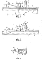
- Les figures 1 et 2 sont des vues en plan d'un appareil suivant l'invention " et
- La figure 3 est une vue partielle en perspective.
- Figures 1 and 2 are plan views of an apparatus according to the invention "and
- Figure 3 is a partial perspective view.
L'appareil se compose de deux flasques 1,
2 verticaux parallèles, écartés l'un de l'autre d'une distance juste supérieure à l'épaisseur des pièces ayant la caractéristique prescrite. Les bords inférieurs des flasques 1 et 2 sont inclinés vers le bas de la droite vers la gauche à la figure 1 et sont raccordés par un fond, de manière à définir un chemin 3 de roulement pour les pièces P de monnaie.The device consists of two
2 parallel verticals, spaced from each other by a distance just greater than the thickness of the pieces having the prescribed characteristic. The lower edges of the
Sur la face extérieure du flasque 1 est fixée une chape 4 dont l'axe 5 est parallèle au flasque 1 et est perpendiculaire à la direction suivie par les pièces P le long du chemin de roulement 3. Deux mâchoires 6 sont solidaires de l'axe 5 et enserrent un aimant 7 permanent, cylindrique. L'axe 8 de l'aimant 7 est perpendiculaire à l'axe 5. L'aimant 7 est en coïncidence avec une ouverture 9, ménagée dans le flasque 1, en amont de la chape 4.On the outer face of the
L'axe 5 est solidaire d'un loquet 10 de verrouillage dont le bec 11, coudé et pointu, est en regard d'une ouverture 12, ménagée dans le flasque 1, en aval de la chape 4. Si R est le rayon d'une pièce P prescrite et 1 la distance entre le bord aval de l'aimant 7 et le bec 11, la relation suivante est vérifiée: R < 1 < 2R.The
Avant le coude du loquet 10, un contrepoids 13 est fixé sur le loquet.Before the bend of the
Comme représenté à la figure 2, en l'absence d'une pièce P magnétique devant l'ouverture 9, et donc en l'absence de forces magnétiques d'attraction de l'aimant 7, le contrepoids 13 exerce un moment suffisamment important par rapport à l'aimant 7 pour que le bec 11 traverse l'ouverture 12 et barre le chemin de roulement 3 en constituant'un obstacle au passage de pièces tant dans un sens que dans l'autre. Mais quand (figure 1) une pièce P ayant la caractéristique prescrite, en l'occurrence la propriété d'être magnétique, passe devant l'ouverture 9, elle attire l'aimant 7. Les mâchoires 6 pivotent et font tourner l'axe 5. Le loquet 10 pivote dans le sens des aiguilles d'une montre, et le bec 11 s'écarte du chemin de roulement 3 par l'ouverture 12 en livrant passage à la pièce P. Comme 1 < 2R, le bord amont de la pièce P se trouve déjà en regard de l'ouverture 12 en empêchant le retour du bec 11 dans le chemin de roulement 3, avant que le bord aval soit trop éloigné de l'aimant 7 pour l'attirer. Comme 1 > R, le bec 11 n'est plus retenu hors du chemin de roulement 3, lorsque le trou de la pièce P vient en regard de l'ouverture 12. Le bec 11 s'engage dans le trou et retient la pièce P.
Dès qu'une pièce P ayant la caractéristique prescrite est passée devant l'ouverture 12, le contrepoids 13 ramène le bec 11 dans le chemin de roulement 3.As shown in FIG. 2, in the absence of a magnetic piece P in front of the
As soon as a part P having the prescribed characteristic has passed in front of the opening 12, the
Claims (8)
Applications Claiming Priority (2)
| Application Number | Priority Date | Filing Date | Title |
|---|---|---|---|
| FR7911597A FR2456354A1 (en) | 1979-05-08 | 1979-05-08 | APPARATUS FOR CHOOSING BETWEEN COINS OR TOKENS |
| FR7911597 | 1979-05-08 |
Publications (1)
| Publication Number | Publication Date |
|---|---|
| EP0018909A1 true EP0018909A1 (en) | 1980-11-12 |
Family
ID=9225184
Family Applications (1)
| Application Number | Title | Priority Date | Filing Date |
|---|---|---|---|
| EP80400586A Withdrawn EP0018909A1 (en) | 1979-05-08 | 1980-04-29 | Apparatus for choosing between coins or tokens |
Country Status (3)
| Country | Link |
|---|---|
| EP (1) | EP0018909A1 (en) |
| JP (1) | JPS5619189A (en) |
| FR (1) | FR2456354A1 (en) |
Families Citing this family (3)
| Publication number | Priority date | Publication date | Assignee | Title |
|---|---|---|---|---|
| DE3411347A1 (en) * | 1984-03-28 | 1985-10-10 | Kienzle Apparate Gmbh, 7730 Villingen-Schwenningen | DEVICE FOR TESTING THE MAGNETIC PROPERTY OF A COIN |
| JPS6250997A (en) * | 1985-08-30 | 1987-03-05 | 株式会社田村電機製作所 | Mechanism for preventing illegal operation by stringed coin |
| GR1000847B (en) * | 1991-09-11 | 1993-02-17 | Dimitrios Karatzias | Slot-machine mechanism |
Citations (5)
| Publication number | Priority date | Publication date | Assignee | Title |
|---|---|---|---|---|
| US1919478A (en) * | 1932-09-09 | 1933-07-25 | Theodore Bibicos | Prevention of iron and steel slugs entering slot machines |
| DE602908C (en) * | 1934-09-19 | Elektrozeit Akt Ges | Coin checker | |
| GB420765A (en) * | 1933-08-08 | 1934-12-07 | David Morgan Griffiths | A magnetical contrivance to prevent iron and steel discs and washers from being inserted through the slots of automatic coin slot machines |
| US2298440A (en) * | 1940-06-12 | 1942-10-13 | Bell Telephone Labor Inc | Coin collector |
| US4111292A (en) * | 1974-12-19 | 1978-09-05 | Dixon Eugene H | Coin machine slug rejector |
-
1979
- 1979-05-08 FR FR7911597A patent/FR2456354A1/en not_active Withdrawn
-
1980
- 1980-04-29 EP EP80400586A patent/EP0018909A1/en not_active Withdrawn
- 1980-05-08 JP JP6003980A patent/JPS5619189A/en active Pending
Patent Citations (5)
| Publication number | Priority date | Publication date | Assignee | Title |
|---|---|---|---|---|
| DE602908C (en) * | 1934-09-19 | Elektrozeit Akt Ges | Coin checker | |
| US1919478A (en) * | 1932-09-09 | 1933-07-25 | Theodore Bibicos | Prevention of iron and steel slugs entering slot machines |
| GB420765A (en) * | 1933-08-08 | 1934-12-07 | David Morgan Griffiths | A magnetical contrivance to prevent iron and steel discs and washers from being inserted through the slots of automatic coin slot machines |
| US2298440A (en) * | 1940-06-12 | 1942-10-13 | Bell Telephone Labor Inc | Coin collector |
| US4111292A (en) * | 1974-12-19 | 1978-09-05 | Dixon Eugene H | Coin machine slug rejector |
Also Published As
| Publication number | Publication date |
|---|---|
| JPS5619189A (en) | 1981-02-23 |
| FR2456354A1 (en) | 1980-12-05 |
Similar Documents
| Publication | Publication Date | Title |
|---|---|---|
| EP0423016A1 (en) | Control method and system for entrance or exit | |
| EP0018909A1 (en) | Apparatus for choosing between coins or tokens | |
| WO1997021898A1 (en) | Self-opening entry device for a controlled access area | |
| LU81894A1 (en) | ROLLER SHUTTER STRUCTURE | |
| IE49071B1 (en) | Anti-stringing device | |
| EP0022712B1 (en) | Apparatus for testing coins or tokens | |
| FR2537762A1 (en) | TAPE CASSETTE COMPRISING A TRANSPARENT WINDOW | |
| BE897722A (en) | AUTOMATIC GATE PARTICULARLY FOR A PASS OF ENTRY INTO A SALES AREA | |
| FR2535876A2 (en) | Mechanism with tokens, difficult to imitate and comprising a magnetic separation means for identifying them from non-magnetic tokens and fake token reject. | |
| EP0305485B1 (en) | Lock with locking-unlocking mechanism using an electromagnet | |
| BE659359A (en) | ||
| JPS6217904Y2 (en) | ||
| FR2595557A1 (en) | DEVICE FOR COMPENSATED GUIDANCE AND GRADUATE OPENING OF THE DOOR OF A CABINET FOR VERTICAL CLASSIFICATION OF SUSPENDED PLANS | |
| EP1191490A1 (en) | Coin meter with solenoid operated ejection mechanism | |
| BE386497A (en) | ||
| EP1318487A1 (en) | Security device for card reader | |
| JPH089803Y2 (en) | Coin falling prevention device in coin dispensing cylinder | |
| NL1008755C2 (en) | Locking mechanism for blocking a valve adjusting member rotatable about an axis of rotation. | |
| FR2582712A1 (en) | Locking device for a metal shutter and the shutter obtained | |
| JPH0418063Y2 (en) | ||
| CH205028A (en) | Device for selecting coins or tokens. | |
| BE404228A (en) | ||
| BE517548A (en) | ||
| BE626300A (en) | ||
| FR2730757A1 (en) | HINGE FOR SWIVEL-MOUNTED DOOR |
Legal Events
| Date | Code | Title | Description |
|---|---|---|---|
| PUAI | Public reference made under article 153(3) epc to a published international application that has entered the european phase |
Free format text: ORIGINAL CODE: 0009012 |
|
| AK | Designated contracting states |
Designated state(s): BE CH DE GB IT LU NL |
|
| 17P | Request for examination filed |
Effective date: 19810108 |
|
| STAA | Information on the status of an ep patent application or granted ep patent |
Free format text: STATUS: THE APPLICATION HAS BEEN WITHDRAWN |
|
| 18W | Application withdrawn |
Withdrawal date: 19810709 |
|
| RIN1 | Information on inventor provided before grant (corrected) |
Inventor name: PIPAUD, LUCIEN MARIE ANDRE |