EP0018908A1 - Moteur linéaire pneumatique - Google Patents
Moteur linéaire pneumatique Download PDFInfo
- Publication number
- EP0018908A1 EP0018908A1 EP80400584A EP80400584A EP0018908A1 EP 0018908 A1 EP0018908 A1 EP 0018908A1 EP 80400584 A EP80400584 A EP 80400584A EP 80400584 A EP80400584 A EP 80400584A EP 0018908 A1 EP0018908 A1 EP 0018908A1
- Authority
- EP
- European Patent Office
- Prior art keywords
- hose
- linear motor
- motor according
- pressing members
- rollers
- Prior art date
- Legal status (The legal status is an assumption and is not a legal conclusion. Google has not performed a legal analysis and makes no representation as to the accuracy of the status listed.)
- Withdrawn
Links
- 239000012530 fluid Substances 0.000 claims abstract description 6
- 239000011248 coating agent Substances 0.000 claims description 8
- 238000000576 coating method Methods 0.000 claims description 8
- 239000013013 elastic material Substances 0.000 claims description 5
- XAGFODPZIPBFFR-UHFFFAOYSA-N aluminium Chemical compound [Al] XAGFODPZIPBFFR-UHFFFAOYSA-N 0.000 description 5
- 229910052782 aluminium Inorganic materials 0.000 description 5
- 230000006835 compression Effects 0.000 description 5
- 238000007906 compression Methods 0.000 description 5
- 229910000831 Steel Inorganic materials 0.000 description 2
- PPBRXRYQALVLMV-UHFFFAOYSA-N Styrene Chemical compound C=CC1=CC=CC=C1 PPBRXRYQALVLMV-UHFFFAOYSA-N 0.000 description 2
- 239000004411 aluminium Substances 0.000 description 2
- 239000000463 material Substances 0.000 description 2
- 210000000056 organ Anatomy 0.000 description 2
- 230000002572 peristaltic effect Effects 0.000 description 2
- 239000004033 plastic Substances 0.000 description 2
- 229920003023 plastic Polymers 0.000 description 2
- 239000010959 steel Substances 0.000 description 2
- 239000000956 alloy Substances 0.000 description 1
- 229910045601 alloy Inorganic materials 0.000 description 1
- NTXGQCSETZTARF-UHFFFAOYSA-N buta-1,3-diene;prop-2-enenitrile Chemical compound C=CC=C.C=CC#N NTXGQCSETZTARF-UHFFFAOYSA-N 0.000 description 1
- 229920001577 copolymer Polymers 0.000 description 1
- 230000009977 dual effect Effects 0.000 description 1
- 239000003562 lightweight material Substances 0.000 description 1
- 238000012423 maintenance Methods 0.000 description 1
- 238000005259 measurement Methods 0.000 description 1
- 239000003960 organic solvent Substances 0.000 description 1
- 229920000915 polyvinyl chloride Polymers 0.000 description 1
- 239000004800 polyvinyl chloride Substances 0.000 description 1
- 230000002028 premature Effects 0.000 description 1
- 238000005096 rolling process Methods 0.000 description 1
- 238000007789 sealing Methods 0.000 description 1
Images

Classifications
-
- F—MECHANICAL ENGINEERING; LIGHTING; HEATING; WEAPONS; BLASTING
- F15—FLUID-PRESSURE ACTUATORS; HYDRAULICS OR PNEUMATICS IN GENERAL
- F15B—SYSTEMS ACTING BY MEANS OF FLUIDS IN GENERAL; FLUID-PRESSURE ACTUATORS, e.g. SERVOMOTORS; DETAILS OF FLUID-PRESSURE SYSTEMS, NOT OTHERWISE PROVIDED FOR
- F15B15/00—Fluid-actuated devices for displacing a member from one position to another; Gearing associated therewith
- F15B15/08—Characterised by the construction of the motor unit
- F15B15/10—Characterised by the construction of the motor unit the motor being of diaphragm type
-
- F—MECHANICAL ENGINEERING; LIGHTING; HEATING; WEAPONS; BLASTING
- F01—MACHINES OR ENGINES IN GENERAL; ENGINE PLANTS IN GENERAL; STEAM ENGINES
- F01B—MACHINES OR ENGINES, IN GENERAL OR OF POSITIVE-DISPLACEMENT TYPE, e.g. STEAM ENGINES
- F01B19/00—Positive-displacement machines or engines of flexible-wall type
- F01B19/04—Positive-displacement machines or engines of flexible-wall type with tubular flexible members
-
- F—MECHANICAL ENGINEERING; LIGHTING; HEATING; WEAPONS; BLASTING
- F15—FLUID-PRESSURE ACTUATORS; HYDRAULICS OR PNEUMATICS IN GENERAL
- F15B—SYSTEMS ACTING BY MEANS OF FLUIDS IN GENERAL; FLUID-PRESSURE ACTUATORS, e.g. SERVOMOTORS; DETAILS OF FLUID-PRESSURE SYSTEMS, NOT OTHERWISE PROVIDED FOR
- F15B15/00—Fluid-actuated devices for displacing a member from one position to another; Gearing associated therewith
- F15B15/08—Characterised by the construction of the motor unit
- F15B15/10—Characterised by the construction of the motor unit the motor being of diaphragm type
- F15B15/106—Characterised by the construction of the motor unit the motor being of diaphragm type the motor being of the pinching-roller type
Definitions
- the present invention relates to a new pneumatic linear motor. More particularly, it relates to a pneumatic linear motor which is both silent and resistant.
- a pneumatic linear motor as described in British Patent No. 1,358,361, operates on the opposite principle to that of peristaltic pumps and essentially consists of a flexible hose capable of withstanding relatively high pressures, a rigid sheath and open longitudinally, and a carriage, movable in the sheath, provided with a device compressing and flattening said hose so as to form on the latter a hermetic constriction to the fluids present between the two ends of the hose, the latter will support on one side on the device and will cause the carriage to move.
- linear motors of the above type are used very little; this is all the more surprising since these linear motors have a very large number of advantages among which one can cite an almost unlimited stroke length, a reduced longitudinal bulk since there overall length is hardly greater than the useful stroke.
- these motors avoid numerous in advantages of cylinders such as sealing, weight, buckling and misalignment problems. This disaffection is easily explained by the fact that all of the linear motors which have been developed and tested up to the present invention require frequent maintenance and are both annoying and of short service life. very rarely exceeding fifteen thousand strokes.
- one of the aims of the present invention is to provide a pneumatic linear motor which is silent, that is to say that in normal operation it produces a maximum of 60 decibels.
- Another object of the present invention is to provide a pneumatic linear motor whose lifespan exceeds one hundred thousand, or even two hundred thousand strokes.
- Another object of the present invention is to provide a pneumatic linear motor which can go fast, that is to say at a speed exceeding 5 meters per second and which can be actuated by small differences in pressure.
- a pneumatic linear motor comprising a hose capable of withstanding relatively high pressures, a rigid sheath and open longitudinally, a carriage movable in the sheath provided with a device compressing and flattening said hose so as to form on the latter a constriction impermeable to the fluids present in the hose, characterized in that said device compresses said hose in an elastic manner so that the force exerted by said device on said hose is substantially constant and equal to a value chosen in advance throughout the stroke of the pneumatic linear motor.
- the device for compressing and flattening said hose in an elastic manner comprises two pressing members which form a slot or a narrow passage through which the hose passes.
- the force applied to the hose must be adjustable and depends, among other factors, on the pressure inside the hose, the diameter of the hose and the device itself. This force can easily be determined using a series of simple tests as described below.
- a force is applied to the hose by means of the device, the value of which is varied. For each value, the hose is put under pressure and it is observed whether the carriage moves or not. We thus arrive at determining the limit value of the force to be applied to the hose so that the carriage moves.
- the force to be chosen for correct operation of the linear motor must preferably be close to but greater than this limit value (approximately 1 to 1.5 times this limit value).
- the force to be applied on one side of the hose is of the order of 80 to 150 newtons (8 to 15 k g-force when the pressing members are rolls of 30 mm in diameter covered with a layer of 2 mm of Adiprene 80 A, elastic material of the type rubbery, and the length of which is 68 mm.
- the elasticity of the compression of the hose is ensured either by coating at least part of the pressing member with an elastic material of rubber type, or by mounting at least one pressing member on a means elastic of the spring type, or preferably by the combination of the two means mentioned above.
- the material coating the pressing members preferably has a shore hardness of between 60 and 100 on the A scale and, preferably, from 70 to 90. It is possible, for example, to choose the product sold under the trade name "Vulcollan", or else the product sold under the name Adiprene 80 A.
- the thickness of the coating of the pressing member is between 1 and 5 millimeters and, preferably, between 2 and 4 millimeters.
- one of the key points determining the longevity of the device lies in the flexibility of the contact between the hose and the pressing members at the fold of the hose. Indeed, a crushing force at this location causes, if it is too great, premature wear of the hose. It is therefore where the hose forms a fold that the thickness constraints of the elastic coating must be best respected. When pebbles are used as organs pressers, it is therefore preferable that the latter compress the areas less. Where the hose forms a fold than the center of the hose.
- the pressing member comprises a roller of revolution
- said roller preferably has a concavity directed towards the axis of revolution, the coating therefore being able to be of variable thickness so that, at rest, the rollers provided with their coating have a cylindrical shape, that is to say that the thickness of the coating varies so as to make up for the concavity, which on this side is a convexity, of the roller.
- the pressing members have a double role: on the one hand, ensuring the tightness of the throat of the hose and, on the other hand, being in contact with the part of the hose under pressure so that the latter exerts on it the pressure that will move the carriage forward.
- the shape and design of the pressing device must take account of this dual function.
- the pressing member must be designed so that the friction forces between the hose and it are as low as possible.
- the pressing member must have a sufficient width, that is to say that its dimension in the plane perpendicular to the generatrices of the hose, is at least substantially equal to the half-circumference of the hose.
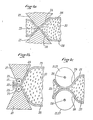
- wedges can be used as the pressing member, that is to say segments of prisms having a triangle as a base, wedges terminated by rollers (FIG. 1b) and preferably rollers ( figure lc).
- the rollers must be of revolution, preferably cylindrical or having a concavity directed towards the axis of revolution.
- the rollers advantageously have an average diameter at least equal to the half diameter of the hose and, preferably, between 0.5 and once the diameter of the hose.
- the elasticity of the contact between the pressurized members and the hose is preferably achieved by mounting at least one of the two on a spring.
- the rigid sheath can be either polyhedral, or preferably cylindrical. It can also be linear or curved. In the latter case, the radius of curvature must be sufficiently large, that is to say at least greater than 10 times the diameter of the cylindrical sheath. Preferably, the axis of curvature is parallel to the axes of revolution of the pressure rollers.
- the carriage must be mounted in the sleeve so as to facilitate its movement inside the latter.
- the cart can be made of different materials, preferably lightweight materials such as plastics, aluminum and its alloys.
- Polyvinyl chloride or the copolymer of acrylonitrile butadiene and styrene known by the acronym ABS can be chosen as plastics.
- the hose must meet a certain number of specifications. These specifications are generally those required from firefighters' hoses. Preferably, it must be resistant to organic solvents when compressed air is used as the fluid using a pump using different types of oil.
- the purpose of the non-limiting exemplary embodiments of the present invention is to enable specialists to easily determine the operating conditions which should be used in each particular case.
- FIGS la, 1b and lc which are schematic sections in the plane perpendicular to the throttle line, show different embodiments of the pressing members.
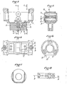
- Figure 2 is a side view of a realization preferred tion of the pneumatic linear motor according to the invention.
- FIG. 3 is a partial section in elevation of the carriage along the line BB of FIGS. 4 and 8.
- Figure 4 is a top view of the same carriage.
- FIG. 5 is a partial section along the line AA in FIG. 3.
- Figure 6 is a left view of the carriage.
- FIG. 7 is a partial section along the line CC of FIG. 3.
- Figure 8 is a top view of the caliper with its rollers.
- the hose 5 filled with a pressurized fluid 20 is between two pressing members 21 to form a tight constriction 22.
- the hose presses on the zones 24 of the pressing members and exerts via these organs a force which ensures the movement of the carriage.
- the pressing members may be corners (FIG. 1a) whose sides form a sufficiently large angle so that the contact zones 24 are sufficiently large.
- rollers 27 rotating around their axes 28, rollers whose average diameter is sufficient for the contact zones 24 between the roller and the hose to be large enough to ensure the proper movement of the carriage (FIG. 1c).
- the linear motor consists of a cylindrical sheath 31 open longitudinally equipped with two flanges 32 and 33 located at each end, these two flanges being provided with end pieces 34 on which the hose 29 is fixed.
- a movable carriage 1 rests on six rollers 11 of ovoid shape movable around their axis 12 mounted on circlip washer.
- This carriage 1 is equipped with a slit device composed of two pressure rollers 10 and 7.
- the pressure roller 10 is movable around the fixed axis 9.
- the pressure roller 7 is movable around the axis 8, which moves in the grooves 35.
- a spring 4 the compression of which can be adjusted using a screw 6 fitted with two nuts 14 and 15, exerts pressure on the two ends of the axis 8 by means of a lifting beam 3.
- the spring 4 is housed in a stirrup serving as a spring barrel 2 fixed by four CHC screws 17 on the carriage.
- the stirrup 2 passes through the sheath through the longitudinal opening 36 and connects the mobile carriage to the part or to the device whose movement is desired.
- the carriage is further equipped with two wheels 13 to guide it into the longitudinal opening 37. These two wheels are put on shoulder UPS screws.
- the linear motor is connected to a pneumatic system allowing the establishment of a pressure difference between the two portions of the hose separated by the carriage.
- the highest pressure can be at will in one or the other of said parts.
- the highest part of the hose exerts a force (force resulting from greater pressure on one side of the hose) on the pressing members (in the zone 24 of FIGS. 1). This force ensures the movement of the carriage.
Landscapes
- Engineering & Computer Science (AREA)
- Mechanical Engineering (AREA)
- General Engineering & Computer Science (AREA)
- Physics & Mathematics (AREA)
- Fluid Mechanics (AREA)
- Actuator (AREA)
- Rigid Pipes And Flexible Pipes (AREA)
Applications Claiming Priority (2)
| Application Number | Priority Date | Filing Date | Title |
|---|---|---|---|
| FR7910739 | 1979-04-27 | ||
| FR7910739A FR2455164A1 (fr) | 1979-04-27 | 1979-04-27 | Moteur lineaire pneumatique |
Publications (1)
| Publication Number | Publication Date |
|---|---|
| EP0018908A1 true EP0018908A1 (fr) | 1980-11-12 |
Family
ID=9224831
Family Applications (1)
| Application Number | Title | Priority Date | Filing Date |
|---|---|---|---|
| EP80400584A Withdrawn EP0018908A1 (fr) | 1979-04-27 | 1980-04-28 | Moteur linéaire pneumatique |
Country Status (2)
| Country | Link |
|---|---|
| EP (1) | EP0018908A1 (show.php) |
| FR (1) | FR2455164A1 (show.php) |
Cited By (1)
| Publication number | Priority date | Publication date | Assignee | Title |
|---|---|---|---|---|
| EP0504450A1 (de) * | 1991-03-20 | 1992-09-23 | Waggonbau Ammendorf Gmbh | Kolbenstangenloser Druckmittelzylinder |
Citations (5)
| Publication number | Priority date | Publication date | Assignee | Title |
|---|---|---|---|---|
| US3534690A (en) * | 1967-12-18 | 1970-10-20 | Ohm Mfg Inc | Fluid pressure actuated conveyor system |
| US3673924A (en) * | 1970-10-05 | 1972-07-04 | Zdzislaw Zakrzewski | Fluid motors |
| DE2250907A1 (de) * | 1972-10-18 | 1974-04-25 | Schuessler Fa Bernd | Rollentrieb |
| GB1358361A (en) * | 1971-11-15 | 1974-07-03 | Inst Ind Research Standards | Fluid pressure power actuator |
| DE2718528A1 (de) * | 1977-04-26 | 1978-11-02 | Siemens Ag | Verfahren und vorrichtung zum antrieb eines vorrichtungsteiles unter verwendung eines in einer schlauchleitung stroemenden gasfoermigen oder fluessigen arbeitsmittels |
-
1979
- 1979-04-27 FR FR7910739A patent/FR2455164A1/fr active Granted
-
1980
- 1980-04-28 EP EP80400584A patent/EP0018908A1/fr not_active Withdrawn
Patent Citations (5)
| Publication number | Priority date | Publication date | Assignee | Title |
|---|---|---|---|---|
| US3534690A (en) * | 1967-12-18 | 1970-10-20 | Ohm Mfg Inc | Fluid pressure actuated conveyor system |
| US3673924A (en) * | 1970-10-05 | 1972-07-04 | Zdzislaw Zakrzewski | Fluid motors |
| GB1358361A (en) * | 1971-11-15 | 1974-07-03 | Inst Ind Research Standards | Fluid pressure power actuator |
| DE2250907A1 (de) * | 1972-10-18 | 1974-04-25 | Schuessler Fa Bernd | Rollentrieb |
| DE2718528A1 (de) * | 1977-04-26 | 1978-11-02 | Siemens Ag | Verfahren und vorrichtung zum antrieb eines vorrichtungsteiles unter verwendung eines in einer schlauchleitung stroemenden gasfoermigen oder fluessigen arbeitsmittels |
Cited By (1)
| Publication number | Priority date | Publication date | Assignee | Title |
|---|---|---|---|---|
| EP0504450A1 (de) * | 1991-03-20 | 1992-09-23 | Waggonbau Ammendorf Gmbh | Kolbenstangenloser Druckmittelzylinder |
Also Published As
| Publication number | Publication date |
|---|---|
| FR2455164A1 (fr) | 1980-11-21 |
| FR2455164B1 (show.php) | 1982-07-30 |
Similar Documents
| Publication | Publication Date | Title |
|---|---|---|
| EP1169549B1 (fr) | Dispositif de transmission mecanique pour moteur a cylindree variable | |
| EP3025060B1 (fr) | Dispositif d'etancheite pour piston | |
| EP0388293B1 (fr) | Tendeur pour courroie de transmission de puissance | |
| FR2859507A1 (fr) | Pompe peristaltique a portee amovible deformable | |
| EP0189345B1 (fr) | Dispositif pour assembler par calandrage au moins une feuille de verre et au moins une pellicule de matière plastique | |
| EP0479647A1 (fr) | Galet tendeur fonctionnant par cisaillement autour d'un centre de rotation fictif et présentant une double rigidité par l'intervention d'une butée | |
| EP2550462B1 (fr) | Palier hydrodynamique destiné à soutenir un cylindre animé d'un mouvement de rotation autour de son axe | |
| FR2711978A1 (fr) | Appareil d'application de tension du type circulaire pour des tôles refendues. | |
| EP0073696A2 (fr) | Mécanisme de transformation d'un nouvement | |
| CA1307163C (fr) | Machine rotative a pistons et a barillet avec rotule de centrage fixe | |
| FR2992382A1 (fr) | Palier a roulement d'excentrique | |
| CA1268062A (fr) | Cylindre a frette tournante | |
| EP0018908A1 (fr) | Moteur linéaire pneumatique | |
| EP0205716A2 (fr) | Dispositif d'obtention de vitesses différentielles tangentielles variables en divers points d'un film déformable | |
| FR3059731A1 (fr) | Pompe hydraulique a pistons axiaux | |
| FR2700531A1 (fr) | Dispositif de traction sur câble. | |
| EP0237437B1 (fr) | Dispositif de réglage du profil d'un cylindre à enveloppe déformable | |
| FR2697589A1 (fr) | Pompe doseuse à membrane à actionnement mécanique. | |
| FR2480889A1 (fr) | Dispositif elastique pour maintenir une courroie a une tension predeterminee et son procede d'utilisation | |
| FR2801526A1 (fr) | Outil portatif d'emmanchement d'un embout dans une extremite d'une conduite | |
| EP3702583B1 (fr) | Pompe volumétrique à piston excentré | |
| FR2966526A1 (fr) | Pompe peristaltique | |
| EP1762646A2 (fr) | Tête d'étanchéite pour machines de traitement thermique de fil | |
| FR2683605A1 (fr) | Dispositif d'entrainement par contact pour convertir de facon reversible un mouvement de rotation en un mouvement lineaire. | |
| FR3043148A1 (fr) | Compresseur a spirales |
Legal Events
| Date | Code | Title | Description |
|---|---|---|---|
| PUAI | Public reference made under article 153(3) epc to a published international application that has entered the european phase |
Free format text: ORIGINAL CODE: 0009012 |
|
| AK | Designated contracting states |
Designated state(s): AT BE CH DE FR GB IT LU NL SE |
|
| 17P | Request for examination filed |
Effective date: 19801201 |
|
| STAA | Information on the status of an ep patent application or granted ep patent |
Free format text: STATUS: THE APPLICATION IS DEEMED TO BE WITHDRAWN |
|
| 18D | Application deemed to be withdrawn |
Effective date: 19840112 |
|
| RIN1 | Information on inventor provided before grant (corrected) |
Inventor name: QUEYRON, ANDRE |