EP0018831A1 - Zusammengesetzter, drucklos betriebsfähiger Luftreifen und dementsprechender Einsatz - Google Patents
Zusammengesetzter, drucklos betriebsfähiger Luftreifen und dementsprechender Einsatz Download PDFInfo
- Publication number
- EP0018831A1 EP0018831A1 EP80301432A EP80301432A EP0018831A1 EP 0018831 A1 EP0018831 A1 EP 0018831A1 EP 80301432 A EP80301432 A EP 80301432A EP 80301432 A EP80301432 A EP 80301432A EP 0018831 A1 EP0018831 A1 EP 0018831A1
- Authority
- EP
- European Patent Office
- Prior art keywords
- insert
- ply
- pneumatic
- sections
- tire
- Prior art date
- Legal status (The legal status is an assumption and is not a legal conclusion. Google has not performed a legal analysis and makes no representation as to the accuracy of the status listed.)
- Granted
Links
Images


Classifications
-
- B—PERFORMING OPERATIONS; TRANSPORTING
- B60—VEHICLES IN GENERAL
- B60C—VEHICLE TYRES; TYRE INFLATION; TYRE CHANGING; CONNECTING VALVES TO INFLATABLE ELASTIC BODIES IN GENERAL; DEVICES OR ARRANGEMENTS RELATED TO TYRES
- B60C17/00—Tyres characterised by means enabling restricted operation in damaged or deflated condition; Accessories therefor
- B60C17/01—Tyres characterised by means enabling restricted operation in damaged or deflated condition; Accessories therefor utilising additional inflatable supports which become load-supporting in emergency
-
- B—PERFORMING OPERATIONS; TRANSPORTING
- B60—VEHICLES IN GENERAL
- B60C—VEHICLE TYRES; TYRE INFLATION; TYRE CHANGING; CONNECTING VALVES TO INFLATABLE ELASTIC BODIES IN GENERAL; DEVICES OR ARRANGEMENTS RELATED TO TYRES
- B60C23/00—Devices for measuring, signalling, controlling, or distributing tyre pressure or temperature, specially adapted for mounting on vehicles; Arrangement of tyre inflating devices on vehicles, e.g. of pumps or of tanks; Tyre cooling arrangements
- B60C23/06—Signalling devices actuated by deformation of the tyre, e.g. tyre mounted deformation sensors or indirect determination of tyre deformation based on wheel speed, wheel-centre to ground distance or inclination of wheel axle
- B60C23/063—Generating directly an audible signal by deformation of the tyre
-
- B—PERFORMING OPERATIONS; TRANSPORTING
- B60—VEHICLES IN GENERAL
- B60C—VEHICLE TYRES; TYRE INFLATION; TYRE CHANGING; CONNECTING VALVES TO INFLATABLE ELASTIC BODIES IN GENERAL; DEVICES OR ARRANGEMENTS RELATED TO TYRES
- B60C19/00—Tyre parts or constructions not otherwise provided for
- B60C2019/006—Warning devices, e.g. devices generating noise due to flat or worn tyres
-
- Y—GENERAL TAGGING OF NEW TECHNOLOGICAL DEVELOPMENTS; GENERAL TAGGING OF CROSS-SECTIONAL TECHNOLOGIES SPANNING OVER SEVERAL SECTIONS OF THE IPC; TECHNICAL SUBJECTS COVERED BY FORMER USPC CROSS-REFERENCE ART COLLECTIONS [XRACs] AND DIGESTS
- Y10—TECHNICAL SUBJECTS COVERED BY FORMER USPC
- Y10T—TECHNICAL SUBJECTS COVERED BY FORMER US CLASSIFICATION
- Y10T152/00—Resilient tires and wheels
- Y10T152/10—Tires, resilient
- Y10T152/10495—Pneumatic tire or inner tube
- Y10T152/10666—Automatic sealing of punctures [e.g., self-healing, etc.]
- Y10T152/10675—Using flowable coating or composition
- Y10T152/10684—On inner surface of tubeless tire
-
- Y—GENERAL TAGGING OF NEW TECHNOLOGICAL DEVELOPMENTS; GENERAL TAGGING OF CROSS-SECTIONAL TECHNOLOGIES SPANNING OVER SEVERAL SECTIONS OF THE IPC; TECHNICAL SUBJECTS COVERED BY FORMER USPC CROSS-REFERENCE ART COLLECTIONS [XRACs] AND DIGESTS
- Y10—TECHNICAL SUBJECTS COVERED BY FORMER USPC
- Y10T—TECHNICAL SUBJECTS COVERED BY FORMER US CLASSIFICATION
- Y10T152/00—Resilient tires and wheels
- Y10T152/10—Tires, resilient
- Y10T152/10495—Pneumatic tire or inner tube
- Y10T152/10666—Automatic sealing of punctures [e.g., self-healing, etc.]
- Y10T152/10675—Using flowable coating or composition
- Y10T152/10702—Using flowable coating or composition within or part of construction of inflating inner tube
-
- Y—GENERAL TAGGING OF NEW TECHNOLOGICAL DEVELOPMENTS; GENERAL TAGGING OF CROSS-SECTIONAL TECHNOLOGIES SPANNING OVER SEVERAL SECTIONS OF THE IPC; TECHNICAL SUBJECTS COVERED BY FORMER USPC CROSS-REFERENCE ART COLLECTIONS [XRACs] AND DIGESTS
- Y10—TECHNICAL SUBJECTS COVERED BY FORMER USPC
- Y10T—TECHNICAL SUBJECTS COVERED BY FORMER US CLASSIFICATION
- Y10T152/00—Resilient tires and wheels
- Y10T152/10—Tires, resilient
- Y10T152/10495—Pneumatic tire or inner tube
- Y10T152/10765—Characterized by belt or breaker structure
- Y10T152/10792—Structure where each bias angle reinforcing cord ply has no opposingly angled ply
-
- Y—GENERAL TAGGING OF NEW TECHNOLOGICAL DEVELOPMENTS; GENERAL TAGGING OF CROSS-SECTIONAL TECHNOLOGIES SPANNING OVER SEVERAL SECTIONS OF THE IPC; TECHNICAL SUBJECTS COVERED BY FORMER USPC CROSS-REFERENCE ART COLLECTIONS [XRACs] AND DIGESTS
- Y10—TECHNICAL SUBJECTS COVERED BY FORMER USPC
- Y10T—TECHNICAL SUBJECTS COVERED BY FORMER US CLASSIFICATION
- Y10T428/00—Stock material or miscellaneous articles
- Y10T428/19—Sheets or webs edge spliced or joined
- Y10T428/192—Sheets or webs coplanar
-
- Y—GENERAL TAGGING OF NEW TECHNOLOGICAL DEVELOPMENTS; GENERAL TAGGING OF CROSS-SECTIONAL TECHNOLOGIES SPANNING OVER SEVERAL SECTIONS OF THE IPC; TECHNICAL SUBJECTS COVERED BY FORMER USPC CROSS-REFERENCE ART COLLECTIONS [XRACs] AND DIGESTS
- Y10—TECHNICAL SUBJECTS COVERED BY FORMER USPC
- Y10T—TECHNICAL SUBJECTS COVERED BY FORMER US CLASSIFICATION
- Y10T428/00—Stock material or miscellaneous articles
- Y10T428/24—Structurally defined web or sheet [e.g., overall dimension, etc.]
- Y10T428/24058—Structurally defined web or sheet [e.g., overall dimension, etc.] including grain, strips, or filamentary elements in respective layers or components in angular relation
- Y10T428/24074—Strand or strand-portions
- Y10T428/24091—Strand or strand-portions with additional layer[s]
-
- Y—GENERAL TAGGING OF NEW TECHNOLOGICAL DEVELOPMENTS; GENERAL TAGGING OF CROSS-SECTIONAL TECHNOLOGIES SPANNING OVER SEVERAL SECTIONS OF THE IPC; TECHNICAL SUBJECTS COVERED BY FORMER USPC CROSS-REFERENCE ART COLLECTIONS [XRACs] AND DIGESTS
- Y10—TECHNICAL SUBJECTS COVERED BY FORMER USPC
- Y10T—TECHNICAL SUBJECTS COVERED BY FORMER US CLASSIFICATION
- Y10T428/00—Stock material or miscellaneous articles
- Y10T428/24—Structurally defined web or sheet [e.g., overall dimension, etc.]
- Y10T428/24058—Structurally defined web or sheet [e.g., overall dimension, etc.] including grain, strips, or filamentary elements in respective layers or components in angular relation
- Y10T428/24074—Strand or strand-portions
- Y10T428/24116—Oblique to direction of web
Definitions
- This invention is directed to a pneumatic tire assembly with run-flat capabilities and to inserts for such assemblies. .Tire deflations that occur unexpectedly during vehicle use, due to punctures, cuts, etc., are potentially hazardous and nearly always inconvenience the user. Known attempts to deal with these problems have led to the development of tire assemblies that can remain in useful operation during and after a substantial loss of air from the tire inflation chamber.
- the run-flat insert permits a deflated tire to remain in operation at limited speeds for a limited distance thus avoiding the immediate inconveniences and hazards that are normally associated with abrupt and unexpected tire deflations as well as tire deflations of a less sudden nature.
- the invention thus seeks to provide a safety tire with run-flat capacity having a warning system that causes discernible vibrations in a wheel axle to alert a driver of a run-flat situation.
- a pneumatic insert for use with a pneumatic tire and wheel rim assembly with the insert disposed within the tire and supported on an annular support surface of the wheel rim, said insert comprising a generally toroidal-shaped hollow member having a pair of sidewall portions and a crown portion joining the sidewall portions, and comprising an annular ply of cord material having at least two sections each of predetermined circumferential extent joined together such that a first one of said sections is a continuation of a second one of said sections, said first section having cords at a first bias angle only with the mid-circumferential plane of the insert and said second section having cords at a second bias angle only with said mid-circumferential plane, said first and second bias angles being dissimilar so that the crown of said insert when inflated has an out-of-round condition.
- the insert is thus of bias ply construction and includes at least one ply section having a relatively high cord angle and at least another ply section having a relatively low cord angle. Both insert ply sections are joined together to form a single ply that is wrapped around a building drum. After the insert has been cured the insert portion formed with the high cord angle ply section will acquire a larger radius than the insert portion formed with the smaller cord angle ply section.
- the contour of the insert is thus provided with two distinct radii corresponding to the relatively high cord angle ply section and the relatively low cord angle ply section. By varying the angular difference between the respective ply sections one can control the difference in radii of the insert. Moreover by using more than two alternate cord angle ply sections in the same insert ply one can generate a corresponding number of alternating radii or lobes. The differences in contour of the insert exist whether the tire cavity is pressurized or not.
- a pneumatic insert is provided with one or more bumps or protrusions on the insert crown portion.
- the circumferential extent of the bump or protrusion is substantially equivalent to the size of the contact patch of the pneumatic insert.
- the bumps can be formed during manufacture of the insert or are adhered to the cured insert in a manner similar to a cold (or hot) recapping process.
- the air escaping from the tire inflation chamber causes the road contacting portion of the tire tread to flatten against the insert crown which provides support for the tread. Air does not simultaneously escape from the insert air chamber because it does not normally communicate with the tire air chamber.
- the different insert radii attributable to different cord angles of the insert ply or the bumps formed on the insert crown cause the tire axle to deflect in a predetermined manner.
- the repeated deflections as the tire rotates cause the axle to vibrate, promoting vibrations in the steering wheel and/or the vehicle body.
- the amplitude and period of the vibrations vary at different speeds. Consequently when the driver is alerted of his run-flat condition he can proceed in a speed range which causes minimal driving discomfort.
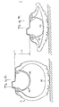
- a -safety tire and rim assembly is generally indicated by the reference number 10 in Fig. 1.
- the assembly 10 comprises a standard tubeless pneumatic tire 12, with a pneumatic insert member 14 both mounted on standard one-piece drop center rim 16.
- the pneumatic tire 12 includes spaced annular bead portions 18 and 20 with sidewalls 22 and 24 extending therefrom and a tread portion 26 bridging the tire sidewalls. Inner surfaces 28, 30, and 32 of the tire sidewalls and tire tread define a Tire cavity 34.
- the pneumatic insert member 14 is of generally toroidal shape and comprises two fabric reinforced rubber plies 36 and 38 wrapped around annular beads 40 and 42 that are of smaller cross section than the tire beads 18 and 20.
- the insert 14 also comprises sidewalls 44 and 46, and a crown portion 48.
- the insert is thus of the general form disclosed in published U.K. application No. 2004234A.
- the insert plies 36 and 38 are laminated orthotropic structures such as rubber impregnated matrices of cord.
- the cords are formed of any suitable material such as rayon with a minimum tensile strength of 53 Kg and 50 to 61 ends per cm, which provides a breaking strength of approximately 1059 to 1270 Kg per cm. Polyester with a tensile strength of from 54 to 58 Kg and approximately 56 ends per cm can also be used, and provides a breaking strength of approximately 1191 to 1267 Kg per cm.
- Other types of fabric such as monofil nylon cords of 2300 denier or a high tensile strength polyamide sold under the designation Keylar can be used as well. The use of steel cords is also feasible.
- the ply 36 comprises at least one ply section 50 (Fig. 10) having a relatively low cord angle A with respect to the mid-circumferential or equatorial plane E of the insert 14 and another ply section 52 having a relatively high cord angle B with respect to the equatorial plane E.
- the ply sections 50 and 52 are formed of the same material differing only in the respective cord angles.
- the ply sections 50 and 52 are cut along their respective cords as shown in Fig. 10 and joined together in an overlap splice 54 (Fig. 11). As seen in Fig. 1 the splice 54 is longer at an edge 56 of the ply 36 than at an edge 58.
- the ply 38 (Fig. 12) is equivalent to the ply 36 in a flipped over condition and includes a low cord angle section 60 corresponding to the section 50, a high cord angle, section 62 corresponding to the section 52, and an overlap splice 64 corresponding to the overlap splice 54.
- the plies 35 and 38 are superimposed with the cords and splice in one layer intersecting the cords and splice of the other layer.
- the splices 54 and 64 are overlapped in criss-cross fashion as shown in Fig. 13 forming a transition region 66.
- the transition region 66 is characterized by a number of multiple ply areas consisting of two, three and four overlapping plies as indicated in Fig. 13.
- the number of overlap splices in each insert ply corresponds to the number of ply sections that form the insert ply.
- an insert ply consisting of two ply sections will have two overlap splices.
- An insert 14 cured in a known manner, and formed of the superimposed plies 36 and 38 is characterized by two transition regions 66 and 68 (Fig. 14) that result from two sets of two overlapping splices such as shown in Fig. 13.
- the transition regions 66 and 68 also represent the boundaries of the low angle ply sections 50, 60 and the high angle ply sections 52, 62.
- the low cord angle ply sections 50, 60 have a radius Rl that is smaller than the radius R2 of the high cord angle ply sections 52, . 62.
- the insert 14 is furnished with-two distinct radii which, for the purposes of this invention, is a desirable nonuniformity.
- a ply 36a comprises a low angle (A) ply section 70 and a high angle (B) ply section 72 cut at the same angle (B).
- the ply sections 70 and 72 are joined together in an overlap splice. 74 (Fig. 16) that is of equal length along both edges 76 and 78 of the ply 36a.
- a ply 38a of this embodiment is equivalent to the ply 36a in a flipped -over condition and includes an overlap splice 80 corresponding to the overlap splice 74.
- the plies 36a and 38a are superimposed with the splices 76 and 80 overlapped in criss-cross fashion forming a transition region 82 consisting of two, three and four overlapping plies as indicated in Fig. 17.
- the overlap splices 74 and 80 of the transition region 82 are of uniform extent along each edge of the superimposed plies 36a, 38a.
- the. area of the overlap splices 54 and 64 in Fig. 13 is dependent upon the angles A and B. In general, the overlap splice area increases as the difference between the angles A and B increases. However, the area of the overlap splices 74 and 80 in Fig. 17 does not depend upon the differences between the angles A and B, and the extent of the overlap can be made quite narrow such as for example 1 . 7 cm .
- An insert 14a as shown in Fig. 18, cured in a known manner and formed of the superimposed plies 36a and 38a, is characterized by two transition regions 82 and 84 that result from two sets of two overlapping splices such as shown in Fig. 17.
- the transition regions 82 and 84 represent the boundaries of the low angle ply sections such as 70 and the high angle ply section such as 72.
- the low cord angle ply sections have a radius Rl that is smaller than the radius R2 of the high cord angle ply sections.
- the transition regions 82 and 84 are narrower than the transition regions 66 and 68 and therefore take up less circumferential extent than the transition regions 66 and 68, and permit generation of a greater number of R 1 and R 2 sections than the Fig. 14 embodiment.
- each ply section 70, 72 (Fig. 16) in the ply 36a for example, one can control the peripheral extent of each circumferential portion defined by the radii Rl and R2 in Figs. 18 and 19.
- the angular difference between ply sections of a single insert ply one can control the difference in radii of the high and low angle sections.
- one can provide circumferential sections having different radii, the magnitudes of which are directly related to the respective selected cord angles for each ply section that comprise the insert ply or plies being used.
- FIG. 22 shows an insert ply 36b formed of ply sections 86 and 88 of different cord angles separated by transition zones 90 and 92.
- the ply sections 88 and 96 are of substantially equal circumferential extent as indicated by the angle C, and the transition zones 90, 98 and 92, 100 are in substantial registration. It is not necessary that the overlapping ply sections be of the same cord angle as long as the selected cord angles furnish a radius in the circumferential region defined by the angle C that is distinctly different from the radius defined in the circumferential section beyond the angle C.
- Fig. 23 differs from Fig. 22 by a predetermined offset D between the transition zones 90, 98 and 92, 100.
- the offset D can exceed the angular .relationships depicted in Fig. 23 and it will be appreciated that such relationships as illustrated are not intended to limit-the scope of the invention.
- the Fig. 23 embodiment will have three distinct radial dimensions and four distinctive circumferential sections. A first radial dimension is attributable to overlapping ply sections having the same cord angle such as B-B, which lie on the major circumferential sections defined between the transition zones 90 and 100.
- a second radial dimension is attributable to overlapping ply sections having different cord angles such as A-B or B-A, which lie between the transition zones 92-100 and, 90-98 respectively.
- a third radial dimension is attributable to overlapping ply sections having the same cord angles such as A-A which lie on the minor circumferential sections defined between the transition zones 98 and 92.
- Fig. 24 shows an insert ply 36c formed of ply sections 102 and 104 of different cord angles separated by transition zones 106 and 108, whereas an insert ply 38c is formed of ply sections 110 and 112 of corresponding different cord angles separated by transition zones 114 and 116.
- the inner ply section 102 is of greater circumferential extent than the corresponding ply section 110.
- Fig. 25 shows an insert ply 36d formed of ply sections 118 and 120 of different cord angles separated by transition zones 122 and 124, whereas an insert ply 38d is formed of ply sections 126 and 128 of corresponding different cord angles separated by transition zones 130 and 132.
- the inner ply section 118 is of smaller circumferential extent than the corresponding ply section 126.
- the Fig. 24 and Fig. 25 embodiments also furnish an insert having three distinct radial dimensions and four distinctive circumferential sections because of overlapping ply sections with A-A cord angles, A-B cord angles, B-A cord angles and B-B cord angles.
- the insert member 14 further includes an outside cover 140 preferably formed of rubber that is less than 0.05 inches thick, an inner diffusion resistant liner 142 preferably formed of chlorobutyl that is less than 0.1 inches thick, and toe strips 144 and 146 around the insert beads 40 and 42.
- a pair of annular rings 148 and 150 henceforth called flaps are respectively joined to the outside surfaces of the insert sidewalls 44 and 46.
- The. flaps 148 and 150 are preferably formed of rubber reinforced fabric ranging in thickness from approximately 0.127 to 0.254 cm.
- the inner diameter of the flaps 148 and 150 are preferably from 5 to 7.6 cm smaller than the diameter of the insert beads 40 and 42.
- the flaps 148 and 150 also preferably extend approximately 3.8 to 5.1 cm below the toe strips 144 and 146 (Fig.'14) and need to extend identical amounts.
- a layer of puncture sealant material 152 (Fig. 1) such as disclosed in U.S. patent 3,981,342 coats the inside surface of the insert member 14.
- a warning system incorporating a pneumatic insert having different radii is of limited value unless the insert is protected against puncture.
- an object such as a nail is picked up by a tire a leak will develop that eventually causes the tire to collapse against the insert. The nail may come in contact with the insert and cause an insert failure. The insert pressure is then liberated into the tire which reinflates momentarily.
- an insert which also loses its air pressure will allow a driver to drive his vehicle until all the insert air pressure is lost. The driver is then forced to stop without warning facing whatever inconveniences and hazards that accompany such a stop.
- the present insert also includes a fear-resistant reinforcement 154 (Fig. 21) provided at the insert crown portion 48 extending into the inscrt sidewalls 44 and 46 above or between the insert plies 36 and 38.
- the reinforcement 154 can comprise a fabric or wire belt, a high modulus rubber strip or any suitable known specially woven tear-resistant fabric such as triaxially woven fabric of chafer fabric.
- the strength of the tear-resistant material can be measured by penetrating the material with a 0.41 cm diameter nail for example, and pulling the nail and material in opposite directions parallel to the plane of the material. The tearing force required to pull the nail a distance of 1.27 cm is measured, since this size hole would allow deflation of an insert even with puncture sealant. An adequate level of protection is obtained by material requiring a tearing force in excess of 27.2 Kg.
- the tear resistant reinforcement 154 in the crown region and the layer of puncture sealant 152 on the inner liner of the insert 14 help the insert to remain in operation even when contacted by objects which lead to a tire failure, as disclosed in detail in my previously referred to patent application. Thus the integrity of the warning system is assured.
- Valve means and other associated structure for inflating the tire 12 and the insert 14, although not shown are also disclosed in detail in my U.K. published application No. 2004234A.
- the mounting and inflation procedures for the tire 12 and the insert 14 are likewise disclosed in detail in said published application.
- the irregularities or non-uniformities in the contour of the insert 14 such as shown in Figs. 6-7 and 18-20 are intended to introduce a vibrating condition in the wheel a:de when a run-flat condition has occurred.
- the vibrations, which are transmitted to the steering wheel or the vehicle body are intended to be atypical of those usually encountered under normal driving conditions and their atypical quality will alert the driver, while the vehicle is still operable, that one of the tires must be repaired.
- a safety tire and wheel assembly 10 in a run-flat condition as shown in Figs. 6 and 7 has an axial deflection J as the tire moves from the position of Fig. 6 to the position of Fig. 7.
- the axial deflection J can be compared to the amplitude of vibrations that. occur in the run-flat condition.
- the frequency of such vibrations is related to the number of sections of the insert 14 having different radii and the vehicle speed.
- axial deflection J relates not only to the differences between Rl and R2 of the insert 14 but also to the ability of insert 14 to resist deflecting a disproportionate amount under load relative to the Rl and R2 dimensions.
- a pneumatic insert 160 (Figs. 4 and 5), which is representative of the prior art, also includes two sections of Rl magnitude and two sections of R2 magnitude.
- the Rl and R2 magnitudes are not attributable to ply sections having different cord angles but to materials having different stretch characteristics under pressure such as disclosed in U.S. patent 3,085,615.
- the R2 section is formed of material which is more stretchable under pressure than the Rl section.
- the R2 section increases in size as the tire pressure drops below that of the insert.
- the R2 section of the insert 160 is more stretchable than the Rl section it is softer under load and will deflect a disproportionately greater amount than the Rl section. Therefore the net deflection K is of lesser magnitude than the deflection J (Figs. 6 and 7) furnished by the present invention. Consequently any run-flat vibrations attributable to the deflection K may not be recognized by a driver- as- being atypical of those usually encountered under normal driving conditions.
- the magnitude of the Rl and R2 sections of the insert 14 in Figs. 6 and 7 does not depend on a reduction in tire pressure below that of the insert.
- the R1 and R2 dimensions of my insert are substantially constant whether the tire cavity is inflated or not. For example when the insert 14 is inflated to 50 psi, which is approximately twice the inflation pressure of passenger tires, and the tire is deflated, the change in insert dimensions is less than 0.5% and the drop in insert inflation pressure is less than 703 K g/m 2 .
- An insert made according to the present invention included two insert plies, each having two ply sections of different cord angles having a 10 degree angular difference and arranged at a 75% high angle -. 25% low angle circumferential relationship as shown in Fig. 18.
- the insert when inflated to 35155 Kg/m 2 , included a minimum radius of 25.27 cm and a maximum radius of 26.42 cm.
- a P205/70 R 14 tire containing the insert was deflected and subjected to normal load conditions (Tire and Rim Association's load rating of 535 Kg at 1828 1 K g/m 2 ).
- the R1 section deflected 2.68 inches under load and the R2 section deflected 6.81 cm under load resulting in a J value of 0.86 cm.
- 0.34/(10.4 - 9.95) or 75% of the difference in radii is translated into axial displacement J.
- one of the insert ply sections can have a cord angle range of 35° to 90° with the angle difference (B-A) between ply sections of an insert ply ranging from 3° to 20°.
- FIG. 2 Another embodiment of my invention, shown in Fig. 2 comprises a pneumatic insert 170 having an out-of-round condition such as a bump 172 formed at a predetermined location on the insert crown 174.
- a pneumatic tire has some enveloping property as it rolls over an object and the greater the enveloping ability of the tire the smoother the resulting ride. Therefore the size of the bump 172 should be comparable to the size of its contact patch between the insert and the tire liner in a run-flat condition.
- the size of the contact patch of a pneumatic insert of 65° drum angle construction is an ellipse with a major axisof 20.32cm and minor axis of 9.53 cm at a rolling radius of 23.62 cm.
- a bump thickness of about 0.76 cm will cause roughness in ride which is bredominant at low speeds (0-48 Km/h)but fades generally at higher speeds.
- the bumps are made of a hard material such as rubber or plastic of Shore A hardness of at least 30. Other materials can also be used provided that they adhere well to the insert and are flexible in order not to break under load. Rubber slabs with a Shore A hardness of 60 are also satisfactory.
- Further embodiments of the invention comprise inserts built with more than one bump at the periphery.
- the number, spacing and thickness of the bumps affect the type of vibration produced inside the vehicle.
- An insert 176 (Fig. 3) with four such bumps 178, 180, 182 and 184 symmetrically placed will produce roughness at low speeds, and a less disturbing vibration at 64-72 K m/h which disappears at higher speeds.
- Still another insert with 4 such bumps but each being 1.27 cm thick instead of 0.76 cm thick will produce roughness up to 72 Km/h which changes gradually to a high frequency vibration up to 97 Km/h.
- the bumps can be a part of the insert during its manufacture. For example after the required layers of ply and rubber are wrapped around a building drum the bumps can be cemented on at the appropriate places around the circumference. The whole assembly can then be shaped and cured in a simple operation. If a mold is used the assembled carcass will have to be positioned so that the bumps fit in respective depressions in the mold surface. Alternatively the bumps can be attached to the uncured carcass after expansion and before the assembly is put into the mold. Still a third method of building the bumps is to adhere the cured (or uncured) slabs to the cured insert in a manner similar to a cold (or hot) recapping process. This method eliminates rubber flow problems.
- a further embodiment of the invention comprises the combination of an insert such as shown in Fig. 18 with a bump such as 172 of Fig. 2.
- the insert need not necessarily be an open toroidal structure as disclosed herein but can be closed at its inner diameter and need not include beads.
- Such inserts are generally shown in the patents previously referred to.
- the type of pneumatic arrangement used is essentially a matter of choice.
- the insert disclosed herein is a two-ply construction further analogous cmbodiments of the invention can be incorporated in an insert with a single ply construction.
- the sections of different radii may be of equal or unequal circumferential extent, and high and low radius portions of the insert may be spaced or repeated several times at different circumferential regions.
- the insert Since the clearance between the insert and the tire can be established to provide contact at a predetermined inflation pressure as the tire loses air the insert thereby functions as a low pressure warning system as well as a run-flat warning system.
- the severity of the vibrations depend upon a number of factors among which are the residual inflation in the tire, the size, number and distribution of the protrusions or lobes around the insert as well as the speed of the vehicle.
- the sensation of a vibration is different at different speeds as shown in the table. Therefore the quality of the vibration or disturbance can be controlled once a run-flat condition has been detected by operating the tire in a speed range that will produce the minimum amount of discomfort.
Applications Claiming Priority (2)
| Application Number | Priority Date | Filing Date | Title |
|---|---|---|---|
| US06/036,611 US4262724A (en) | 1979-05-03 | 1979-05-03 | Low pressure and run-flat warning system for a pneumatic tire |
| US36611 | 1979-05-03 |
Publications (2)
| Publication Number | Publication Date |
|---|---|
| EP0018831A1 true EP0018831A1 (de) | 1980-11-12 |
| EP0018831B1 EP0018831B1 (de) | 1983-04-20 |
Family
ID=21889588
Family Applications (1)
| Application Number | Title | Priority Date | Filing Date |
|---|---|---|---|
| EP80301432A Expired EP0018831B1 (de) | 1979-05-03 | 1980-05-01 | Zusammengesetzter, drucklos betriebsfähiger Luftreifen und dementsprechender Einsatz |
Country Status (5)
| Country | Link |
|---|---|
| US (1) | US4262724A (de) |
| EP (1) | EP0018831B1 (de) |
| JP (1) | JPS595446B2 (de) |
| CA (1) | CA1115189A (de) |
| DE (1) | DE3062809D1 (de) |
Cited By (5)
| Publication number | Priority date | Publication date | Assignee | Title |
|---|---|---|---|---|
| EP0844111A1 (de) * | 1996-11-26 | 1998-05-27 | Compagnie Générale des Etablissements MICHELIN-MICHELIN & CIE | Sicherheitseinlage mit Warnfunktion |
| WO1999038715A1 (fr) * | 1998-01-30 | 1999-08-05 | Compagnie Generale Des Etablissements Michelin - Michelin & Cie | Insert de securite avertisseur |
| FR2774335A1 (fr) * | 1998-01-30 | 1999-08-06 | Michelin & Cie | Insert de securite avertisseur |
| CN108349335A (zh) * | 2015-11-13 | 2018-07-31 | 凯斯纽荷兰(中国)管理有限公司 | 用于控制轮胎压力的控制回路 |
| CN108349336A (zh) * | 2015-11-13 | 2018-07-31 | 凯斯纽荷兰(中国)管理有限公司 | 用于控制轮胎轮的压力的控制回路 |
Families Citing this family (24)
| Publication number | Priority date | Publication date | Assignee | Title |
|---|---|---|---|---|
| ZA811396B (en) * | 1980-03-13 | 1982-04-28 | Dunlop Ltd | Tyre treads and tyres |
| US4580519A (en) * | 1980-10-29 | 1986-04-08 | Brewer Howell K | Low tire pressure warning device |
| JPS5868408U (ja) * | 1981-10-31 | 1983-05-10 | 横浜ゴム株式会社 | 空気タイヤとリムからなる車輪 |
| JPS61191369U (de) * | 1985-05-21 | 1986-11-28 | ||
| US4674549A (en) * | 1985-09-03 | 1987-06-23 | The Budd Company | Bead lock device |
| JPH05162505A (ja) * | 1991-12-10 | 1993-06-29 | Sadayuki Yamada | トレツドを二重にしたスノータイヤ |
| US5246050A (en) * | 1992-07-10 | 1993-09-21 | The Goodyear Tire & Rubber Company | Tubeless shield and assembly |
| FR2694398A1 (fr) * | 1992-08-03 | 1994-02-04 | Michelin & Cie | Procédé et dispositifs de détection de la mise en appui d'un pneumatique sur un appui de sécurité. |
| DE4329528C1 (de) * | 1993-09-02 | 1995-03-09 | Continental Ag | Fahrschlauch und Verfahren zu seiner Herstellung |
| DE69831797T2 (de) | 1997-04-18 | 2006-07-13 | Compagnie Générale des Etablissements Michelin-Michelin & Cie., Clermont-Ferrand | Sicherheitseinsatz, der ein Vibrationssignal in Querrichtung erzeugt, und Vorrichtung zum Detektieren des Aufliegens eines Reifens auf einem Einsatz |
| FR2762260A1 (fr) * | 1997-04-18 | 1998-10-23 | Michelin & Cie | Insert de securite generant un signal vibratoire transversal et dispositif de detection de la mise en appui d'un pneumatique sur un insert |
| FR2780682A1 (fr) * | 1998-07-06 | 2000-01-07 | Michelin Rech Tech | Procede et dispositif de detection d'une condition de roulage a plat d'un pneumatique - inserts, roues et pneumatiques concus pour ce procede |
| FR2784055B1 (fr) | 1998-10-02 | 2000-12-22 | Valeo Electronique | Procede et dispositif pour la detection de la signature vibratoire d'un insert de securite equipant un pneumatique |
| US7418988B2 (en) * | 1999-12-10 | 2008-09-02 | Michelin Recherche Et Technique S.A. | Non-pneumatic tire |
| US6367528B1 (en) | 2000-02-28 | 2002-04-09 | The Goodyear Tire & Rubber Company | Tire deflection alarm |
| US6688359B2 (en) | 2001-08-31 | 2004-02-10 | Michelin Recherche Et Technique, S.A. | Pneumatic inner liner for a tire |
| JP4166601B2 (ja) * | 2003-03-25 | 2008-10-15 | 横浜ゴム株式会社 | タイヤホイール組立体 |
| GB0314628D0 (en) * | 2003-06-24 | 2003-07-30 | Thompson Roger | A wheel |
| US8617333B2 (en) * | 2007-09-20 | 2013-12-31 | The Goodyear Tire & Rubber Company | Pneumatic tire having built-in sealant layer and preparation thereof |
| US20090078353A1 (en) * | 2007-09-21 | 2009-03-26 | Ramendra Nath Majumdar | Pneumatic Tire Having Built-In Sealant Layer And Preparation Thereof |
| US20090084482A1 (en) * | 2007-09-28 | 2009-04-02 | Ramendra Nath Majumdar | Pneumatic tire having built-In sealant layer and preparation thereof |
| US8316903B2 (en) | 2007-10-01 | 2012-11-27 | The Goodyear Tire & Rubber Company | Pneumatic tire having built-in sealant layer and preparation thereof |
| CA2915483C (en) | 2013-06-15 | 2021-11-16 | Ronald Thompson | Annular ring and non-pneumatic tire |
| US10953696B2 (en) | 2015-02-04 | 2021-03-23 | Camso Inc | Non-pneumatic tire and other annular devices |
Citations (3)
| Publication number | Priority date | Publication date | Assignee | Title |
|---|---|---|---|---|
| US3085615A (en) * | 1960-04-04 | 1963-04-16 | Goodyear Tire & Rubber | Flat tire warning device |
| DE2448315A1 (de) * | 1974-10-10 | 1976-04-22 | Continental Gummi Werke Ag | Notlaufring fuer luftbereifungen |
| GB2004234A (en) * | 1977-09-14 | 1979-03-28 | Uniroyal Inc | Pneumatic tyre and wheel rim assembly and an assembly and a pneumatic safety insert for use in such assembly |
Family Cites Families (7)
| Publication number | Priority date | Publication date | Assignee | Title |
|---|---|---|---|---|
| US1144239A (en) * | 1915-02-23 | 1915-06-22 | Reinforced Inner Tube Company | Inner tube for pneumatic tires. |
| US2713372A (en) * | 1950-04-20 | 1955-07-19 | Firestone Tire & Rubber Co | Tubeless tire and safety diaphragm combination |
| US2884983A (en) * | 1952-09-06 | 1959-05-05 | Cuesta Francisco Gonzalez | Safety pneumatic tire wheel |
| US2754876A (en) * | 1953-05-05 | 1956-07-17 | Firestone Tire & Rubber Co | Safety tire |
| FR1378047A (fr) * | 1963-06-04 | 1964-11-13 | Michelin & Cie | Perfectionnements aux enveloppes de pneumatiques |
| JPS5244085A (en) * | 1975-10-03 | 1977-04-06 | Toshiba Corp | Outside lead wire bending device for lamp tube |
| JPS5813363B2 (ja) * | 1977-07-07 | 1983-03-14 | オ−ツタイヤ株式会社 | 車輪 |
-
1979
- 1979-05-03 US US06/036,611 patent/US4262724A/en not_active Expired - Lifetime
- 1979-08-31 CA CA334,835A patent/CA1115189A/en not_active Expired
-
1980
- 1980-05-01 EP EP80301432A patent/EP0018831B1/de not_active Expired
- 1980-05-01 DE DE8080301432T patent/DE3062809D1/de not_active Expired
- 1980-05-02 JP JP55057983A patent/JPS595446B2/ja not_active Expired
Patent Citations (3)
| Publication number | Priority date | Publication date | Assignee | Title |
|---|---|---|---|---|
| US3085615A (en) * | 1960-04-04 | 1963-04-16 | Goodyear Tire & Rubber | Flat tire warning device |
| DE2448315A1 (de) * | 1974-10-10 | 1976-04-22 | Continental Gummi Werke Ag | Notlaufring fuer luftbereifungen |
| GB2004234A (en) * | 1977-09-14 | 1979-03-28 | Uniroyal Inc | Pneumatic tyre and wheel rim assembly and an assembly and a pneumatic safety insert for use in such assembly |
Cited By (9)
| Publication number | Priority date | Publication date | Assignee | Title |
|---|---|---|---|---|
| EP0844111A1 (de) * | 1996-11-26 | 1998-05-27 | Compagnie Générale des Etablissements MICHELIN-MICHELIN & CIE | Sicherheitseinlage mit Warnfunktion |
| US6039099A (en) * | 1996-11-26 | 2000-03-21 | Compagnie Generale Des Etablisse-Michelin-Michelin & Cie | Safety insert with warning function |
| WO1999038715A1 (fr) * | 1998-01-30 | 1999-08-05 | Compagnie Generale Des Etablissements Michelin - Michelin & Cie | Insert de securite avertisseur |
| FR2774335A1 (fr) * | 1998-01-30 | 1999-08-06 | Michelin & Cie | Insert de securite avertisseur |
| US6543500B1 (en) | 1998-01-30 | 2003-04-08 | COMPAGNIE GéNéRALE DES ETABLISSEMENTS MICHELIN & CIE | Alarm safety insert |
| CN108349335A (zh) * | 2015-11-13 | 2018-07-31 | 凯斯纽荷兰(中国)管理有限公司 | 用于控制轮胎压力的控制回路 |
| CN108349336A (zh) * | 2015-11-13 | 2018-07-31 | 凯斯纽荷兰(中国)管理有限公司 | 用于控制轮胎轮的压力的控制回路 |
| CN108349335B (zh) * | 2015-11-13 | 2020-04-17 | 凯斯纽荷兰(中国)管理有限公司 | 用于控制轮胎压力的控制回路 |
| CN108349336B (zh) * | 2015-11-13 | 2020-04-21 | 凯斯纽荷兰(中国)管理有限公司 | 用于控制轮胎轮的压力的控制回路 |
Also Published As
| Publication number | Publication date |
|---|---|
| EP0018831B1 (de) | 1983-04-20 |
| DE3062809D1 (en) | 1983-05-26 |
| US4262724A (en) | 1981-04-21 |
| JPS562205A (en) | 1981-01-10 |
| CA1115189A (en) | 1981-12-29 |
| JPS595446B2 (ja) | 1984-02-04 |
Similar Documents
| Publication | Publication Date | Title |
|---|---|---|
| EP0018831B1 (de) | Zusammengesetzter, drucklos betriebsfähiger Luftreifen und dementsprechender Einsatz | |
| US5263526A (en) | Pneumatic tire having specified bead structure | |
| US4153095A (en) | Pneumatic tire having a pneumatic safety insert with beads | |
| US4405007A (en) | Pneumatic safety tire | |
| JP5284307B2 (ja) | クラウン強化のためのアンダーレイ構造 | |
| US4248286A (en) | Safety support assembly for pneumatic tires | |
| CA2412644A1 (en) | Structurally supported resilient tire with bias ply carcass | |
| US20040244892A1 (en) | Runflat tire system and support ring therefor | |
| JP4342724B2 (ja) | トレッドの支持膜 | |
| US4246948A (en) | Pneumatic tire having a pneumatic safety insert with beads | |
| JPS6219300B2 (de) | ||
| JPH0732827A (ja) | 安全車輪及びその中子 | |
| JP2000127711A5 (de) | ||
| JPS5981207A (ja) | 空気入りタイヤ | |
| AU708113B2 (en) | Low pressure all terrain vehicle tire | |
| JP4866523B2 (ja) | タイヤトレッド支持膜 | |
| CA1143644A (en) | Low pressure and run-flat warning system for a pneumatic tire | |
| EP0426389B1 (de) | Luftreifen | |
| US5151141A (en) | Tire and rim | |
| JP3735447B2 (ja) | 空気入りタイヤ | |
| CA1153677A (en) | Low pressure and run-flat warning system for a pneumatic tire | |
| JP2005507338A (ja) | 改善されたビード構造体を備えた自動車ホイール用のタイヤ | |
| JP3428680B2 (ja) | 安全車輪及びその中子 | |
| KR102646626B1 (ko) | 비공기압 타이어 | |
| KR20060072054A (ko) | 타이어 |
Legal Events
| Date | Code | Title | Description |
|---|---|---|---|
| PUAI | Public reference made under article 153(3) epc to a published international application that has entered the european phase |
Free format text: ORIGINAL CODE: 0009012 |
|
| AK | Designated contracting states |
Designated state(s): DE FR GB IT SE |
|
| 17P | Request for examination filed |
Effective date: 19810410 |
|
| ITF | It: translation for a ep patent filed |
Owner name: DE DOMINICIS & MAYER S.R.L. |
|
| GRAA | (expected) grant |
Free format text: ORIGINAL CODE: 0009210 |
|
| AK | Designated contracting states |
Designated state(s): DE FR GB IT SE |
|
| REF | Corresponds to: |
Ref document number: 3062809 Country of ref document: DE Date of ref document: 19830526 |
|
| ET | Fr: translation filed | ||
| PGFP | Annual fee paid to national office [announced via postgrant information from national office to epo] |
Ref country code: FR Payment date: 19840319 Year of fee payment: 5 |
|
| PGFP | Annual fee paid to national office [announced via postgrant information from national office to epo] |
Ref country code: DE Payment date: 19840419 Year of fee payment: 5 |
|
| PGFP | Annual fee paid to national office [announced via postgrant information from national office to epo] |
Ref country code: SE Payment date: 19840630 Year of fee payment: 5 |
|
| PG25 | Lapsed in a contracting state [announced via postgrant information from national office to epo] |
Ref country code: SE Effective date: 19850502 |
|
| GBPC | Gb: european patent ceased through non-payment of renewal fee | ||
| PG25 | Lapsed in a contracting state [announced via postgrant information from national office to epo] |
Ref country code: FR Free format text: LAPSE BECAUSE OF NON-PAYMENT OF DUE FEES Effective date: 19860131 |
|
| PG25 | Lapsed in a contracting state [announced via postgrant information from national office to epo] |
Ref country code: DE Effective date: 19860201 |
|
| REG | Reference to a national code |
Ref country code: FR Ref legal event code: ST |
|
| PG25 | Lapsed in a contracting state [announced via postgrant information from national office to epo] |
Ref country code: GB Effective date: 19881118 |
|
| EUG | Se: european patent has lapsed |
Ref document number: 80301432.3 Effective date: 19860702 |
|
| PLBE | No opposition filed within time limit |
Free format text: ORIGINAL CODE: 0009261 |
|
| STAA | Information on the status of an ep patent application or granted ep patent |
Free format text: STATUS: NO OPPOSITION FILED WITHIN TIME LIMIT |