EP0018251B1 - Procédé de contrôle de calage d'un allumeur de véhicule automobile - Google Patents
Procédé de contrôle de calage d'un allumeur de véhicule automobile Download PDFInfo
- Publication number
- EP0018251B1 EP0018251B1 EP19800400408 EP80400408A EP0018251B1 EP 0018251 B1 EP0018251 B1 EP 0018251B1 EP 19800400408 EP19800400408 EP 19800400408 EP 80400408 A EP80400408 A EP 80400408A EP 0018251 B1 EP0018251 B1 EP 0018251B1
- Authority
- EP
- European Patent Office
- Prior art keywords
- advance
- speed
- engine
- rotation
- function
- Prior art date
- Legal status (The legal status is an assumption and is not a legal conclusion. Google has not performed a legal analysis and makes no representation as to the accuracy of the status listed.)
- Expired
Links
- 238000000034 method Methods 0.000 title claims description 16
- 238000002485 combustion reaction Methods 0.000 claims description 3
- 238000006243 chemical reaction Methods 0.000 claims description 2
- 239000002184 metal Substances 0.000 claims 1
- 238000005259 measurement Methods 0.000 description 3
- 238000012800 visualization Methods 0.000 description 3
- 238000010586 diagram Methods 0.000 description 2
- 230000003068 static effect Effects 0.000 description 2
- 238000013475 authorization Methods 0.000 description 1
- 230000000903 blocking effect Effects 0.000 description 1
- 239000003086 colorant Substances 0.000 description 1
- 238000006073 displacement reaction Methods 0.000 description 1
- 230000000694 effects Effects 0.000 description 1
- 230000035899 viability Effects 0.000 description 1
Images
Classifications
-
- F—MECHANICAL ENGINEERING; LIGHTING; HEATING; WEAPONS; BLASTING
- F02—COMBUSTION ENGINES; HOT-GAS OR COMBUSTION-PRODUCT ENGINE PLANTS
- F02P—IGNITION, OTHER THAN COMPRESSION IGNITION, FOR INTERNAL-COMBUSTION ENGINES; TESTING OF IGNITION TIMING IN COMPRESSION-IGNITION ENGINES
- F02P17/00—Testing of ignition installations, e.g. in combination with adjusting; Testing of ignition timing in compression-ignition engines
- F02P17/02—Checking or adjusting ignition timing
- F02P17/04—Checking or adjusting ignition timing dynamically
Definitions
- the known methods are essentially of two types: static timing, that is to say engine stopped, or dynamic timing, that is to say engine in operation.
- the static stalling process is used when the additional means made available to the operator are very limited and limited to the possession of a device enabling the opening or closing of a contact of the igniter to be observed.
- the engine being placed in the top dead center of the first cylinder, the manipulation consists in orienting the igniter in order to place itself at the limit of the opening of the contacts of the contact grains of the igniter breaker, this result being observed at using the device allowing to observe the opening or closing previously connected.
- the dynamic setting process is the most traditionally used.
- the work consists in orienting the igniter until a mark placed on the flywheel coincides with a fixed mark, the whole being lit by the lamp of a strobe being controlled.
- the ignition signals (or tops) requesting the spark plug of the first cylinder to be able to carry out this operation, the engine must first be brought to the speed appropriate to the advance value existing between the two marks.
- the object of the present invention is to increase the timing accuracy of any type of igniter with control of the mechanical or magnetic ignition signal comprising a centrifugal advance system as a function of the rotation speed of the engine and for this purpose relates a timing control method of an internal combustion engine igniter for a motor vehicle, ignition type of the control type, of the ignition point, mechanical or magnetic, comprising an ignition advance device as a function of the speed of rotation of the engine such as using metallic masses driven in rotation by the axis of the igniter and subjected to the reaction of springs which act in traction, characterized in that from a signal of the ignition and of the engine rotation speed is produced a voltage U1 as a function of the effective advance of the igniter to be checked, which voltage is then compared to a reference voltage U3, which is a function of a reference advance, developed from vi tesse of rotation of the engine and of coordinates of two points of an advance curve of a type chosen as a function of the igniter to be checked, said comparison being visualized using signals, which indicate the direction
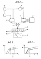
- the mark 1 indicates the igniter mounted on a vehicle engine
- the mark 2 indicates a speed sensor which takes the speed of the engine on which the igniter 1 is mounted.
- the signals from the sensor 2 and from the igniter 1 are transformed by a device 3 into a voltage U1 as a function of the true advance of the igniter considered.
- the signals from the sensor 2 are transformed into a voltage U2 by means of a transformer4; this voltage U2 is then exploited using an element 5 into which are inserted coordinates, coming from a storage element 6, of two points M and N defining a segment corresponding to a portion of the curve of the ideal advance, surrounding a selected speed of rotation of the engine for said igniter 1 considered.
- This element 5 then develops a voltage U3 called the reference voltage.
- the voltages U1 and U3 are then compared using a comparator7.
- the signal from comparator 7 is then used to control the display of the offset between the true advance of the igniter 1 and the ideal advance created.
- This visualization is carried out using an element 8, which can, as necessary, be only information using indicator lights 8 indicating the direction and the order of magnitude of said offset or more precise and give a value real difference between the true advance and the ideal advance for a small difference between these two advances.
- Such a method essentially consists in eliminating the influence of the fluctuations in the speed of rotation of the motor on the reading of the comparison during the control.
- the adjustment point will therefore be chosen in zone C of FIG. 2 and may be processed by the user by a method of comparison of a reference voltage U3 representative of the advance to be obtained and of a voltage U1 reflecting the 'true advance.
- the reference voltage will therefore be defined on the one hand by the speed of rotation of the motor and on the other hand by the coordinates of two points M and N delimiting the portion of curve of said setpoint voltage (see fig. 2).
- a galvanometer q can take up the central zone corresponding to the indicator 8a in order to increase the precision of the setting of the setting.
Landscapes
- Engineering & Computer Science (AREA)
- Chemical & Material Sciences (AREA)
- Combustion & Propulsion (AREA)
- Mechanical Engineering (AREA)
- General Engineering & Computer Science (AREA)
- Electrical Control Of Ignition Timing (AREA)
- Ignition Installations For Internal Combustion Engines (AREA)
Applications Claiming Priority (2)
| Application Number | Priority Date | Filing Date | Title |
|---|---|---|---|
| FR7909263 | 1979-04-12 | ||
| FR7909263A FR2453987A1 (fr) | 1979-04-12 | 1979-04-12 | Procede de controle de calage d'un allumeur de vehicule automobile |
Publications (2)
| Publication Number | Publication Date |
|---|---|
| EP0018251A1 EP0018251A1 (fr) | 1980-10-29 |
| EP0018251B1 true EP0018251B1 (fr) | 1982-04-07 |
Family
ID=9224253
Family Applications (1)
| Application Number | Title | Priority Date | Filing Date |
|---|---|---|---|
| EP19800400408 Expired EP0018251B1 (fr) | 1979-04-12 | 1980-03-27 | Procédé de contrôle de calage d'un allumeur de véhicule automobile |
Country Status (5)
| Country | Link |
|---|---|
| EP (1) | EP0018251B1 (show.php) |
| DE (1) | DE3060274D1 (show.php) |
| ES (1) | ES490452A0 (show.php) |
| FR (1) | FR2453987A1 (show.php) |
| PT (1) | PT71083A (show.php) |
Family Cites Families (2)
| Publication number | Priority date | Publication date | Assignee | Title |
|---|---|---|---|---|
| GB1467078A (en) * | 1973-06-01 | 1977-03-16 | Scans Associates Inc | Method and apparatus for determining the average timing angle in internal combustion engines |
| FR2294337A1 (fr) * | 1974-12-10 | 1976-07-09 | Peugeot & Renault | Appareil permettant le reglage de l'avance a l'allumage |
-
1979
- 1979-04-12 FR FR7909263A patent/FR2453987A1/fr active Granted
-
1980
- 1980-03-27 DE DE8080400408T patent/DE3060274D1/de not_active Expired
- 1980-03-27 EP EP19800400408 patent/EP0018251B1/fr not_active Expired
- 1980-04-10 ES ES490452A patent/ES490452A0/es active Granted
- 1980-04-10 PT PT7108380A patent/PT71083A/pt unknown
Also Published As
| Publication number | Publication date |
|---|---|
| FR2453987B1 (show.php) | 1983-12-16 |
| PT71083A (fr) | 1980-05-01 |
| EP0018251A1 (fr) | 1980-10-29 |
| ES8101203A1 (es) | 1980-12-01 |
| ES490452A0 (es) | 1980-12-01 |
| FR2453987A1 (fr) | 1980-11-07 |
| DE3060274D1 (en) | 1982-05-19 |
Similar Documents
| Publication | Publication Date | Title |
|---|---|---|
| FR2463935A1 (fr) | Dispositif pour la detection de la vitesse de rotation et la detection d'un angle de rotation d'un arbre, en particulier du vilebrequin d'un moteur a combustion interne | |
| FR2543221A1 (fr) | Procede et dispositif pour determiner l'instant d'injection dans les moteurs a combustion interne pendant le processus de demarrage | |
| FR2470263A1 (fr) | Analyseur de moteur | |
| FR2770902A1 (fr) | Dispositif servant a detecter la rotation d'une piece, y compris son sens de rotation | |
| EP0010033B1 (fr) | Capteur de position angulaire pour moteur à combustion interne équipé d'un système d'allumage électronique | |
| EP0018251B1 (fr) | Procédé de contrôle de calage d'un allumeur de véhicule automobile | |
| FR2541456A1 (fr) | Dispositif pour afficher et/ou memoriser des defauts de dispositifs indicateurs sur des moteurs a combustion interne | |
| EP0101342B1 (fr) | Procédé d'optimisation de l'avance à l'allumage pour moteur à combustion interne | |
| EP0032333B1 (fr) | Dispositif de détection de défauts de combustion dans un moteur à explosions | |
| EP0027411B1 (fr) | Procédé pour mesurer la puissance d'un moteur de véhicule automobile sur un banc à rouleaux, et banc de mesure pour la mise en oeuvre de ce procédé | |
| FR2566839A1 (fr) | Capteur destine a detecter le passage d'un piston ou groupe de pistons d'un moteur a combustion interne par la position du point mort haut | |
| FR2529674A1 (fr) | Procede et installation de mesure des caracteristiques dynamiques d'un systeme tournant, notamment d'un moteur electrique | |
| FR2570634A1 (fr) | Dispositif pour maintenir, de facon telecommandee, en bon etat des parties d'une installation nucleaire protegee | |
| FR2488081A1 (fr) | Installation pour la determination de l'instant de declenchement d'un signal | |
| EP0128817A1 (fr) | Procédé de réglage et de mesure du vieillissement d'un moteur à combustion interne | |
| FR2680833A1 (fr) | Procede et dispositif de detection de l'encrassement d'une bougie. | |
| FR2860176A3 (fr) | Dispositif de controle pour cle dynamometrique | |
| EP0412017B1 (fr) | Procédé et dispositif de détection pour le système d'injection électronique d'un moteur multicylindre | |
| FR2523214A1 (fr) | Dispositif et procede de determination de la position du piston dans le cylindre d'un moteur a mouvement alternatif | |
| EP0889235B1 (fr) | Dispositif de détermination de la phase de fonctionnement d'un moteur à combustion interne | |
| EP0187071B1 (fr) | Système électronique d'élaboration d'un signal synchrone d'un signal d'allumage de moteur à combustion interne | |
| EP0150642A2 (fr) | Dispositif de détection de référence angulaire d 'une pièce dentée tournante | |
| WO1988007630A1 (fr) | Dispositif et procede de verification du cablage du module de puissance d'allumage | |
| FR2656379A1 (fr) | Dispositif pour la commande et/ou la regulation du dosage du carburant et/ou de l'angle d'allumage d'un moteur a combustion interne. | |
| FR2584499A1 (fr) | Procede pour detecter des fluctuations de la vitesse de rotation d'un moteur a combustion interne. |
Legal Events
| Date | Code | Title | Description |
|---|---|---|---|
| PUAI | Public reference made under article 153(3) epc to a published international application that has entered the european phase |
Free format text: ORIGINAL CODE: 0009012 |
|
| AK | Designated contracting states |
Designated state(s): DE GB IT SE |
|
| 17P | Request for examination filed |
Effective date: 19801002 |
|
| ITF | It: translation for a ep patent filed | ||
| GRAA | (expected) grant |
Free format text: ORIGINAL CODE: 0009210 |
|
| AK | Designated contracting states |
Designated state(s): DE GB IT |
|
| REF | Corresponds to: |
Ref document number: 3060274 Country of ref document: DE Date of ref document: 19820519 |
|
| PGFP | Annual fee paid to national office [announced via postgrant information from national office to epo] |
Ref country code: DE Payment date: 19840405 Year of fee payment: 5 |
|
| GBPC | Gb: european patent ceased through non-payment of renewal fee | ||
| PG25 | Lapsed in a contracting state [announced via postgrant information from national office to epo] |
Ref country code: DE Effective date: 19871201 |
|
| PG25 | Lapsed in a contracting state [announced via postgrant information from national office to epo] |
Ref country code: GB Effective date: 19881118 |
|
| PLBE | No opposition filed within time limit |
Free format text: ORIGINAL CODE: 0009261 |
|
| STAA | Information on the status of an ep patent application or granted ep patent |
Free format text: STATUS: NO OPPOSITION FILED WITHIN TIME LIMIT |