EP0018158B1 - Appareil à dénuder des câbles - Google Patents
Appareil à dénuder des câbles Download PDFInfo
- Publication number
- EP0018158B1 EP0018158B1 EP19800301122 EP80301122A EP0018158B1 EP 0018158 B1 EP0018158 B1 EP 0018158B1 EP 19800301122 EP19800301122 EP 19800301122 EP 80301122 A EP80301122 A EP 80301122A EP 0018158 B1 EP0018158 B1 EP 0018158B1
- Authority
- EP
- European Patent Office
- Prior art keywords
- aperture
- carrier
- cable
- tool
- blade
- Prior art date
- Legal status (The legal status is an assumption and is not a legal conclusion. Google has not performed a legal analysis and makes no representation as to the accuracy of the status listed.)
- Expired
Links
Images

Classifications
-
- H—ELECTRICITY
- H02—GENERATION; CONVERSION OR DISTRIBUTION OF ELECTRIC POWER
- H02G—INSTALLATION OF ELECTRIC CABLES OR LINES, OR OF COMBINED OPTICAL AND ELECTRIC CABLES OR LINES
- H02G1/00—Methods or apparatus specially adapted for installing, maintaining, repairing or dismantling electric cables or lines
- H02G1/12—Methods or apparatus specially adapted for installing, maintaining, repairing or dismantling electric cables or lines for removing insulation or armouring from cables, e.g. from the end thereof
- H02G1/1202—Methods or apparatus specially adapted for installing, maintaining, repairing or dismantling electric cables or lines for removing insulation or armouring from cables, e.g. from the end thereof by cutting and withdrawing insulation
- H02G1/1204—Hand-held tools
- H02G1/1221—Hand-held tools the cutting element rotating about the wire or cable
- H02G1/1224—Hand-held tools the cutting element rotating about the wire or cable making a transverse cut
Definitions
- This invention relates to a wire stripper, i.e. a tool for use in stripping the sheathing from an electrical conductor by making a peripheral slit in the sheathing and moving the tool axially relative to the conductor so as to sever and remove a portion of the sheathing.
- British patent GB-A-811822 provides a simple tool for this purpose in which a pair of cutting blades are mounted on respective body parts which can be moved towards one another against spring loading so that Vee shaped cutting edges cooperate to make a diamond shaped aperture which is reduced in dimensions as the body parts approach one another.
- the minimum size of the aperture, and hence the depth of cut into a predetermined cable is fixed due to the construction employed.
- German DE-A-2523148 proposes a tool which has plier like parts, one of which carries a plurality of cutters which can be individually adjusted to different depths, and which can all be adjuated relative to one another to vary the positions of the cuts axially along the cable (within narrow limits) and which is intended for coaxial cables. Whilst this tool avoids the necessity for adjustment between carrying out the separate cuts on a co-axial cable, it is unsuitable for ordinary cables.
- the object of the invention is to provide a simple and relatively inexpensive tool for stripping cables, suitable for use with a range of difference cable sizes or with co-axial cables, and which overcomes these problems.
- a tool for stripping cables comprises a body formed with at least one aperture, a blade carrier which is movable relative to the body towards and away from the aperture, a stop limiting travel of the carrier in the direction towards the aperture, at least one blade extending across the aperture, and means connecting the blade to the carrier for adjusting their relative positions so that when a cable extends through said aperture and the carrier is against the stop the depth of cut of the blade into the cable depends upon the said adjustment means, and is characterised in that said carrier is urged by spring means in the direction which takes the blade towards and across the aperture.
- the invention avoids the use of parts which have to be closed together to embrace the cable, since instead of two movable parts there is one body with an aperture for the cable.
- the invention uses a spring to drive the cutter, and hence complete stripping becomes more likely, and the problem of providing efficient stripping in such a tool is solved.
- a plurality of apertures is provided in the body, with the same number of blades as apertures, each blade being associated with separate connection means whereby a plurality of depth of cut settings can be maintained.
- each aperture to be used with a different cable size, so that a range of cables can be dealt with without interfering with the settings, or it enables the different depth cuts with co-axial cable to be made and again without interfering with the other settings.
- it when so used with co-axial cables, it enables the axial separation of the cuts to be selected without limit.
- the tool body is in the form of a housing in which the carrier is slidably mounted and the housing and carrier are formed with holes to enable the user to withdraw the carrier from its limiting position by inserting his finger through the holes and retracting the carrier.
- the holes in the housing may for example be pyriforme with their major axes extending in the direction of movement of the carrier and the hole in the carrier may be circular.
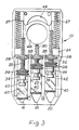
- the tool comprises a housing 10 consisting of two tray- like halves 12, 14. Adjacent one end, each housing portion 12, 14 is formed with three apertures 16, 18 and 20 aligned one with each of the corresponding apertures in the other housing portion so that a cable 22 can be inserted through any one pair of registering apertures in the manner indicated in Figure 2.
- the apertures 16, 18 and 20 are of a tapering configuration for reasons that will become apparent subsequently and, in the embodiment illustrated, each aperture comprises a semicircular portion and a V-shaped portion, the apices of the V's being located closest to the adjacent end of the housing.
- the margins of the apertures 16, 18 and 20 may be formed with flanges which project inwardly of the housing so as to provide extended support for the cable.
- a blade carrier 24 is mounted within the housing 10 for sliding movement lengthwise of the housing towards and away from the apertures 16, 18 and 20.
- the blade-carrier is limited in its movement towards the apertures 16, 18 and 20 by suitable stop means, for example internal shoulders 26 within the housing, and is biassed towards this limiting position by springs 27.
- the carrier 24 is formed with a number of internally threaded bores which receive respective screw-threaded rods 28, 30 and 32.
- the rods 28, 30 and 32 extend lengthwise of the housing towards respective ones of the apertures 16, 18 and 20 and terminate in portions 34 which are rotatably connected with the rods 28, 30 and 32 and are provided with knurled sections 36 by means of which the rods 28, 30 and 32 can be adjusted relative to the carrier 24 in the lengthwise direction.
- Lock nuts 38 are also provided for securing the rods, in a selected position of adjustment, the lock nuts 38 also including knurled sections to aid manipulation thereof. In the area of the lock nut 38 and the knurled sections 36 of portions 34, the housing portions 12, 14 are cut away to allow the user access to these components for the purposes of adjustment.
- the portions 34 are each connected to a respective blade 40 which are guided for sliding movement within the housing and are formed with generally T-shaped slots for reception of the heads 42 and portions 34.
- the blades 40 undergo corresponding adjustments and it will be understood from Figure 3 that the extent to which the blades 40 encroach upon the apertures 16, 18-and 20 can be varied by appropriate adjustment of the rods 28, 30 and 32.
- the housing portions 12, 14 are formed with slots 44 and the carrier 24 is formed with an opening 46 so that the user can effect retraction of the blade-carrier by inserting the finger through the holes 44 and 46 and pulling the carrier in the appropriate direction. During this action, the extent to which the blades 40 encroach upon the apertures 16, 18 and 20 is reduced to facilitate insertion of the cable.
- the housing portion 14 Adjacent each of the apertures 16, 18 and 20, the housing portion 14 is formed with apertures 48 forming sockets for reception of spigot portions of L-shaped stop elements 50 which can be arranged to overlie respective ones of the apertures 16, 18 and 20 to limit the extent to which the cable can be inserted through the housing and hence the length of sheath etc. that can be stripped.
- the stop elements will be made in a range of sizes so that the user can select the appropriate size for the length of sheath etc. to be stripped.
- the blades 40 are set by means of adjustment of the rods 28, 30 and 32 so as to produce an incision of predetermined depth for given cable size.
- the blade 40 associated with aperture 20 is intended to produce an incision of predetermined depth into the outer sheathing of a co-axial cable
- the blade 40 associated with aperture 18 is set to make an incision into the mesh-like conductor of the cable
- the blade 40 associated with the aperture 16 is set to make an incision of predetermined depth into the sleeve surrounding the inner conductor of the cable.
- the carrier 24 is retracted to enable the cable to be inserted into aperture 20, the cable is inserted until it comes into abutment with the corresponding stop element, the carrier is released so that the blade associated with aperture 20 makes the required incision and the incision can then be extended around the complete periphery of the cable by rotating the tool about the cable while the cable end is maintained in abutment with the corresponding stop element 50.
- the outer sheathing is then removed by pulling the tool axially of the cable and after removal of the outer sheathing, the same procedure can be carried out for the remaining elements of the cable which are to be stripped, the subsequent operations being carried out using the apertures 18 and 16 respectively.
- the settings of the blades are adjusted accordingly by releasing the lock nuts 38 and rotating the portions 34.
- the tapering configuration of the apertures 16, 18 and 20 caters for the differing diameters of the respective elements of a given size of co- axial cable.
- the tool can be used for other types of cable.
- the tool will be particularly useful in instances where electrical assembly work involves stripping of a limited range of for example single conductor cables, each blade being set for the cutting of a different sized cable of the range.
Landscapes
- Removal Of Insulation Or Armoring From Wires Or Cables (AREA)
Claims (6)
Applications Claiming Priority (2)
| Application Number | Priority Date | Filing Date | Title |
|---|---|---|---|
| GB7913948 | 1979-04-21 | ||
| GB7913948 | 1979-04-21 |
Publications (2)
| Publication Number | Publication Date |
|---|---|
| EP0018158A1 EP0018158A1 (fr) | 1980-10-29 |
| EP0018158B1 true EP0018158B1 (fr) | 1983-01-26 |
Family
ID=10504696
Family Applications (1)
| Application Number | Title | Priority Date | Filing Date |
|---|---|---|---|
| EP19800301122 Expired EP0018158B1 (fr) | 1979-04-21 | 1980-04-09 | Appareil à dénuder des câbles |
Country Status (4)
| Country | Link |
|---|---|
| EP (1) | EP0018158B1 (fr) |
| JP (1) | JPS6322127B2 (fr) |
| DE (1) | DE3061740D1 (fr) |
| WO (1) | WO1980002345A1 (fr) |
Families Citing this family (5)
| Publication number | Priority date | Publication date | Assignee | Title |
|---|---|---|---|---|
| GB2133226B (en) * | 1983-01-07 | 1986-07-02 | Zdzislaw Bieganski | Cable stripper |
| GB2226461B (en) * | 1988-12-22 | 1993-05-26 | Zdzislaw Bieganski | Coaxial cable stripper |
| US7565740B2 (en) | 2004-12-01 | 2009-07-28 | Corning Gilbert Inc. | Method for standardizing coaxial cable jacket diameters |
| GB2543002B (en) * | 2014-07-03 | 2020-12-09 | Ppc Broadband Inc | Modular blade cartridge for a cable stripping tool and a stripping tool utilizing a modular blade cartridge |
| US10418796B2 (en) | 2016-03-27 | 2019-09-17 | Southwire Company, Llc | Cable stripper |
Family Cites Families (4)
| Publication number | Priority date | Publication date | Assignee | Title |
|---|---|---|---|---|
| GB611822A (en) * | 1946-05-09 | 1948-11-04 | Gerald Stains Ltd | Improvements in or relating to cutting tools |
| US2738479A (en) * | 1951-10-04 | 1956-03-13 | Warren H Kintzinger | Plural wire stripper and electrical connector |
| GB1102808A (en) * | 1965-09-22 | 1968-02-14 | John Jackson Turner | Improvements in or relating to wire-stripping tools |
| DE2523148C2 (de) * | 1975-05-24 | 1982-04-15 | Licentia Patent-Verwaltungs-Gmbh, 6000 Frankfurt | Absetzwerkzeug für Koaxialkabel |
-
1980
- 1980-04-02 JP JP50067080A patent/JPS6322127B2/ja not_active Expired
- 1980-04-02 WO PCT/GB1980/000061 patent/WO1980002345A1/fr unknown
- 1980-04-09 EP EP19800301122 patent/EP0018158B1/fr not_active Expired
- 1980-04-09 DE DE8080301122T patent/DE3061740D1/de not_active Expired
Also Published As
| Publication number | Publication date |
|---|---|
| JPS6322127B2 (fr) | 1988-05-10 |
| DE3061740D1 (en) | 1983-03-03 |
| WO1980002345A1 (fr) | 1980-10-30 |
| JPS56500436A (fr) | 1981-04-02 |
| EP0018158A1 (fr) | 1980-10-29 |
Similar Documents
| Publication | Publication Date | Title |
|---|---|---|
| US4366619A (en) | Cable stripper | |
| US4345375A (en) | Cable tool | |
| EP0251704A2 (fr) | Appareil à dénuder des câbles électriques et similaires | |
| US6687991B2 (en) | Method for removing an outer sheath of an electrical cable | |
| US5062192A (en) | Cable stripping tool | |
| US5732471A (en) | Wire stripper with integral cable sheath cutter | |
| US5009006A (en) | Cable stripping tool | |
| GB2153158A (en) | Co-axial cable end portion preparation | |
| US6618945B2 (en) | Microcable stripping tool | |
| EP0018158B1 (fr) | Appareil à dénuder des câbles | |
| EP0184897A1 (fr) | Pince pour le dénudage d'un câble | |
| CN215419363U (zh) | 一种电气工程用的剥线装置 | |
| US2752676A (en) | Universal protective covering cutter for coaxial and other cables | |
| US3237300A (en) | Insulation cutting pliers having parallel longitudinal and transverse cutting edges | |
| JPS6133329B2 (fr) | ||
| US4934219A (en) | Coaxial cable stripper tool and method | |
| US4953428A (en) | Tool for stripping cables, in particular constituted cables | |
| US6079105A (en) | Cable sheath stripping tool | |
| US3361015A (en) | End stripping tool | |
| US8141219B2 (en) | Tool for assisting in cutting the conductors of an electrical cable to a precise length | |
| GB2219696A (en) | Cable shield stripping apparatus | |
| US5009005A (en) | Cable stripper | |
| EP0990929A2 (fr) | Procédé et dispositif pour enlever la gaine d'une fibre optique | |
| US3014387A (en) | Sheath cutting tool for working sheath covered cables | |
| US6067715A (en) | Wire and cable stripping tool |
Legal Events
| Date | Code | Title | Description |
|---|---|---|---|
| PUAI | Public reference made under article 153(3) epc to a published international application that has entered the european phase |
Free format text: ORIGINAL CODE: 0009012 |
|
| AK | Designated contracting states |
Designated state(s): DE FR GB NL SE |
|
| 17P | Request for examination filed |
Effective date: 19810422 |
|
| GRAA | (expected) grant |
Free format text: ORIGINAL CODE: 0009210 |
|
| AK | Designated contracting states |
Designated state(s): DE FR GB NL SE |
|
| PG25 | Lapsed in a contracting state [announced via postgrant information from national office to epo] |
Ref country code: SE Effective date: 19830126 |
|
| REF | Corresponds to: |
Ref document number: 3061740 Country of ref document: DE Date of ref document: 19830303 |
|
| ET | Fr: translation filed | ||
| PGFP | Annual fee paid to national office [announced via postgrant information from national office to epo] |
Ref country code: FR Payment date: 19840227 Year of fee payment: 5 |
|
| PGFP | Annual fee paid to national office [announced via postgrant information from national office to epo] |
Ref country code: DE Payment date: 19840628 Year of fee payment: 5 |
|
| REG | Reference to a national code |
Ref country code: GB Ref legal event code: 732 |
|
| REG | Reference to a national code |
Ref country code: FR Ref legal event code: TP |
|
| PGFP | Annual fee paid to national office [announced via postgrant information from national office to epo] |
Ref country code: NL Payment date: 19860430 Year of fee payment: 7 |
|
| PG25 | Lapsed in a contracting state [announced via postgrant information from national office to epo] |
Ref country code: NL Effective date: 19871101 |
|
| NLV4 | Nl: lapsed or anulled due to non-payment of the annual fee | ||
| PG25 | Lapsed in a contracting state [announced via postgrant information from national office to epo] |
Ref country code: FR Free format text: LAPSE BECAUSE OF NON-PAYMENT OF DUE FEES Effective date: 19871230 |
|
| GBPC | Gb: european patent ceased through non-payment of renewal fee | ||
| PG25 | Lapsed in a contracting state [announced via postgrant information from national office to epo] |
Ref country code: DE Effective date: 19880101 |
|
| REG | Reference to a national code |
Ref country code: FR Ref legal event code: ST |
|
| PG25 | Lapsed in a contracting state [announced via postgrant information from national office to epo] |
Ref country code: GB Effective date: 19881118 |
|
| PLBE | No opposition filed within time limit |
Free format text: ORIGINAL CODE: 0009261 |
|
| STAA | Information on the status of an ep patent application or granted ep patent |
Free format text: STATUS: NO OPPOSITION FILED WITHIN TIME LIMIT |