EP0017596B1 - Dispositif photorécepteur à faible bruit - Google Patents
Dispositif photorécepteur à faible bruit Download PDFInfo
- Publication number
- EP0017596B1 EP0017596B1 EP80400472A EP80400472A EP0017596B1 EP 0017596 B1 EP0017596 B1 EP 0017596B1 EP 80400472 A EP80400472 A EP 80400472A EP 80400472 A EP80400472 A EP 80400472A EP 0017596 B1 EP0017596 B1 EP 0017596B1
- Authority
- EP
- European Patent Office
- Prior art keywords
- level
- output
- signal
- transducer
- main amplifier
- Prior art date
- Legal status (The legal status is an assumption and is not a legal conclusion. Google has not performed a legal analysis and makes no representation as to the accuracy of the status listed.)
- Expired
Links
- 238000005286 illumination Methods 0.000 claims abstract 2
- 108091008695 photoreceptors Proteins 0.000 description 11
- 230000010287 polarization Effects 0.000 description 11
- 241001644893 Entandrophragma utile Species 0.000 description 7
- 238000010586 diagram Methods 0.000 description 6
- 230000000694 effects Effects 0.000 description 3
- 235000021183 entrée Nutrition 0.000 description 3
- 230000007423 decrease Effects 0.000 description 2
- 241001080024 Telles Species 0.000 description 1
- 230000003321 amplification Effects 0.000 description 1
- 238000004458 analytical method Methods 0.000 description 1
- 230000005540 biological transmission Effects 0.000 description 1
- 238000001914 filtration Methods 0.000 description 1
- 230000004907 flux Effects 0.000 description 1
- 238000003199 nucleic acid amplification method Methods 0.000 description 1
- 230000003287 optical effect Effects 0.000 description 1
- 239000004065 semiconductor Substances 0.000 description 1
- 238000000926 separation method Methods 0.000 description 1
Images
Classifications
-
- H—ELECTRICITY
- H03—ELECTRONIC CIRCUITRY
- H03G—CONTROL OF AMPLIFICATION
- H03G3/00—Gain control in amplifiers or frequency changers
- H03G3/20—Automatic control
- H03G3/30—Automatic control in amplifiers having semiconductor devices
- H03G3/3084—Automatic control in amplifiers having semiconductor devices in receivers or transmitters for electromagnetic waves other than radiowaves, e.g. lightwaves
-
- G—PHYSICS
- G01—MEASURING; TESTING
- G01S—RADIO DIRECTION-FINDING; RADIO NAVIGATION; DETERMINING DISTANCE OR VELOCITY BY USE OF RADIO WAVES; LOCATING OR PRESENCE-DETECTING BY USE OF THE REFLECTION OR RERADIATION OF RADIO WAVES; ANALOGOUS ARRANGEMENTS USING OTHER WAVES
- G01S7/00—Details of systems according to groups G01S13/00, G01S15/00, G01S17/00
- G01S7/48—Details of systems according to groups G01S13/00, G01S15/00, G01S17/00 of systems according to group G01S17/00
- G01S7/491—Details of non-pulse systems
- G01S7/493—Extracting wanted echo signals
-
- H—ELECTRICITY
- H01—ELECTRIC ELEMENTS
- H01J—ELECTRIC DISCHARGE TUBES OR DISCHARGE LAMPS
- H01J43/00—Secondary-emission tubes; Electron-multiplier tubes
- H01J43/04—Electron multipliers
- H01J43/30—Circuit arrangements not adapted to a particular application of the tube and not otherwise provided for
-
- H—ELECTRICITY
- H04—ELECTRIC COMMUNICATION TECHNIQUE
- H04B—TRANSMISSION
- H04B10/00—Transmission systems employing electromagnetic waves other than radio-waves, e.g. infrared, visible or ultraviolet light, or employing corpuscular radiation, e.g. quantum communication
- H04B10/60—Receivers
-
- H—ELECTRICITY
- H10—SEMICONDUCTOR DEVICES; ELECTRIC SOLID-STATE DEVICES NOT OTHERWISE PROVIDED FOR
- H10F—INORGANIC SEMICONDUCTOR DEVICES SENSITIVE TO INFRARED RADIATION, LIGHT, ELECTROMAGNETIC RADIATION OF SHORTER WAVELENGTH OR CORPUSCULAR RADIATION
- H10F77/00—Constructional details of devices covered by this subclass
- H10F77/95—Circuit arrangements
- H10F77/953—Circuit arrangements for devices having potential barriers
- H10F77/959—Circuit arrangements for devices having potential barriers for devices working in avalanche mode
Definitions
- the present invention relates to photoreceptor devices, and applies in particular to telecommunications and electro-optical telemetry.
- Photoreceptor devices are already known comprising a photoelectric transducer with polarization variable multiplying factor, such as an avalanche photodiode or a photomultiplier tube. To this transducer are added a controlled polarization circuit, a main amplifier mounted between the output of the photomultiplier and the output terminal of the photoreceptor device, and a bias control chain mounted between the output of the main amplifier and the input. of the polarization circuit.
- electro-optical rangefinders currently operate at a very long distance, and it is the signal-to-noise ratio of the photoreceptor transducer that defines the maximum suitable operating distance.
- the main object of the present invention is to provide a photoreceptor device having a very suitable signal-to-noise ratio.
- the output terminal finally gives the useful signal, a noise multiplied by the transducer, due to the ambient lighting as well as to the specific characteristics of the transducer, and a noise not multiplied by the transducer, due only to specific characteristics of the transducer and the main amplifier.
- the auxiliary signal By passing the auxiliary signal through the main amplifier, one avoids the temperature drifts of the electronic circuits, since this auxiliary signal crosses the same amplifier stages as the useful signal and the noises.
- the multiplication of the useful signal level by the transducer being proportional to M 2
- the multiplication of the noise level by the transducer being proportional to M d , where is a quantity linked to the transducer, and which varies between 2.3 and 3 as a function of the multiplier factor M, K is less than
- the servo chain prefferably includes a broadband amplifier inserted between the output of the main amplifier and the inputs of the two detector circuits.
- the auxiliary signal is an alternating sinusoidal signal.
- Said predetermined polarization imposed by the polarization circuit when the level N s of the useful signal is much higher than the levels N b and N x of the noises is advantageously chosen to define a multiplying factor equal to a few units approximately.
- the photoelectric transducer used according to the present invention is preferably an avalanche photodiode, but it is also possible to use a photomultiplier tube.
- the Applicant has also observed that the use of avalanche gain in an avalanche photodiode makes it possible to increase the output signal of the photodiode, and thereby reduce the effect of the noise of the amplifier which follows it.
- the practical problem is that beyond a certain threshold, which varies with temperature, the increase in the multiplying factor of the avalanche photodiode is accompanied by a very rapid increase in noise.
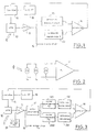
- FIG. 1 illustrates the block diagram of a photodetector device according to the invention.
- an avalanche photodiode 10 receives a light flux 0 consisting for example of an infrared beam modulated at a frequency F of the order of 10 MHz.
- the output of the photodiode 10, including an electrical signal of frequency F, is applied to a main amplifier; and the output thereof gives on the output terminal 12, in addition to the noises, a useful signal which will then be processed by the reception circuits of a range finder.
- the avalanche photodiode 10 receives a polarization voltage defined by the polarization control circuit 15, from a high voltage supply circuit 16 (the polarization voltages commonly reach one hundred volts).
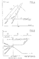
- the useful signal current i s depends on the useful photocurrent I Ph , in the photodiode, on the modulation index m of the received light beam, as well as on the multiplier factor M of the avalanche photodiode; the mean value of the useful signal level is written:
- the average value of the amplified noise level can be written:
- the unamplified noise current i x depends on the series resistance of the photodiode, its surface leakage current, and the noise current of the amplifier stage, reduced to its input. These parameters, which can be known in advance, are noted l x .
- the average value of the non-amplified noise level is written:
- N x is known in advance.
- N b + Nx K where K is less than [d / (d - 2)] N , which is known in advance.
- K is less than [d / (d - 2)] N , which is known in advance.
- values of K very close to [d / (d - 2)] N x may be suitable, but it is generally desirable to take a value of K which is not too close to
- a detector circuit 13 ( Figure 1) rectifies the output of the main amplifier 11, thus providing a level: signal which is applied to a first input of a comparator 14.
- a reference circuit 20 produces an auxiliary reference level, predetermined, equal to K, applied to the second input of comparator 14.
- the levels of useful signal N s and of multiplied noise N b participate together in the control of the multiplier factor M, which provides automatic gain control, an advantageous property in particular in rangefinders.
- the automatic gain control is essentially carried out according to the useful signal.
- the polarization circuit fixes a predetermined polarization of the photodiode, corresponding to a small multiplying factor of the order of a few units (5 for example).
- the gain M is constant, and the servo no longer acts.
- the signal level can be adjusted, if necessary, by acting on the optical transmission of the system (diaphragm; gray filter) or on the gain of the electronics downstream of 12.
- the reference signal is applied to the input of the main amplifier 11, with the output signal of the photodiode 10. It retains the level 2 ⁇ N x , taking into account the amplification factors concerned; but it consists of a signal located in a frequency band outside that of the useful signal. Preferably, it is a pure sinusoidal signal whose frequency F r is of the order of 7 to 8 MHz.
- the output of the main amplifier 11 is applied to a wideband auxiliary amplifier 17, followed by the aforementioned detector circuit 13, which now includes a notch filter eliminating the frequency band from the reference signal, then a level detector 131 , the output of which arrives at the first input of comparator 14.
- a second detector assembly also connected to the output of the broadband amplifier 17, comprises a bandpass filter 230, selecting the frequency band of the reference signal, then a level detector 231, the output of which is connected to the second input of comparator 14.
- the device of the invention appreciably improves the performance of a photoreceptor device with an avalanche photodiode. This applies in particular to electro-optical rangefinders operating at long distance, regardless of the ambient lighting.
Landscapes
- Physics & Mathematics (AREA)
- Engineering & Computer Science (AREA)
- Electromagnetism (AREA)
- Computer Networks & Wireless Communication (AREA)
- General Physics & Mathematics (AREA)
- Remote Sensing (AREA)
- Radar, Positioning & Navigation (AREA)
- Signal Processing (AREA)
- Optical Radar Systems And Details Thereof (AREA)
- Optical Communication System (AREA)
- Photometry And Measurement Of Optical Pulse Characteristics (AREA)
- Control Of Amplification And Gain Control (AREA)
- Amplifiers (AREA)
- Photoreceptors In Electrophotography (AREA)
- Nuclear Medicine (AREA)
Priority Applications (1)
| Application Number | Priority Date | Filing Date | Title |
|---|---|---|---|
| AT80400472T ATE12547T1 (de) | 1979-04-10 | 1980-04-09 | Rauscharmer photoempfaenger. |
Applications Claiming Priority (2)
| Application Number | Priority Date | Filing Date | Title |
|---|---|---|---|
| FR7909057 | 1979-04-10 | ||
| FR7909057A FR2454105A1 (fr) | 1979-04-10 | 1979-04-10 | Dispositif photorecepteur a faible bruit |
Publications (2)
| Publication Number | Publication Date |
|---|---|
| EP0017596A1 EP0017596A1 (fr) | 1980-10-15 |
| EP0017596B1 true EP0017596B1 (fr) | 1985-04-03 |
Family
ID=9224175
Family Applications (1)
| Application Number | Title | Priority Date | Filing Date |
|---|---|---|---|
| EP80400472A Expired EP0017596B1 (fr) | 1979-04-10 | 1980-04-09 | Dispositif photorécepteur à faible bruit |
Country Status (4)
| Country | Link |
|---|---|
| EP (1) | EP0017596B1 (enExample) |
| AT (1) | ATE12547T1 (enExample) |
| DE (1) | DE3070409D1 (enExample) |
| FR (1) | FR2454105A1 (enExample) |
Families Citing this family (5)
| Publication number | Priority date | Publication date | Assignee | Title |
|---|---|---|---|---|
| GB2122447B (en) * | 1982-06-17 | 1985-11-13 | Standard Telephones Cables Ltd | Optical receiver |
| FR2571148B1 (fr) * | 1984-09-28 | 1987-01-02 | Electricite De France | Detecteur de faisceau lumineux a photodiode a circuit de reglage du point de fonctionnement |
| DE3870493D1 (de) * | 1987-03-17 | 1992-06-04 | Siemens Ag | Regelung des multiplikationsfaktors von lawinenphotodioden in optischen empfaengern. |
| EP0783808B1 (en) * | 1994-09-03 | 2000-08-02 | International Business Machines Corporation | Optical transmitter and transceiver module for wireless data transmission |
| US7309852B2 (en) * | 2004-10-18 | 2007-12-18 | Avago Technologies Ecbu Ip (Singapore) Pte Ltd. | Variable noise control for an optical transducer |
Family Cites Families (2)
| Publication number | Priority date | Publication date | Assignee | Title |
|---|---|---|---|---|
| US3644740A (en) * | 1969-07-22 | 1972-02-22 | Hughes Aircraft Co | Control circuit for biasing a photodetector so as to maintain a selected false alarm rate |
| US3898452A (en) * | 1974-08-15 | 1975-08-05 | Itt | Electron multiplier gain stabilization |
-
1979
- 1979-04-10 FR FR7909057A patent/FR2454105A1/fr active Granted
-
1980
- 1980-04-09 DE DE8080400472T patent/DE3070409D1/de not_active Expired
- 1980-04-09 EP EP80400472A patent/EP0017596B1/fr not_active Expired
- 1980-04-09 AT AT80400472T patent/ATE12547T1/de not_active IP Right Cessation
Non-Patent Citations (1)
| Title |
|---|
| Pulse, Digital and Switching Waveforms, MacGraw Hill, 1965, page 248, 7-11 * |
Also Published As
| Publication number | Publication date |
|---|---|
| FR2454105B1 (enExample) | 1983-11-18 |
| EP0017596A1 (fr) | 1980-10-15 |
| ATE12547T1 (de) | 1985-04-15 |
| FR2454105A1 (fr) | 1980-11-07 |
| DE3070409D1 (en) | 1985-05-09 |
Similar Documents
| Publication | Publication Date | Title |
|---|---|---|
| EP1740962B1 (fr) | Procede et dispositif de mesure avec detection synchrone et echantillonnage correle | |
| FR2938659A3 (fr) | Dispositif de mesure de distance par laser | |
| EP0658977A1 (fr) | Amplificateur à gain variable | |
| EP0017596B1 (fr) | Dispositif photorécepteur à faible bruit | |
| FR2735930A1 (fr) | Recepteur optique ayant une fonction de suppression des composantes inutiles de modulation d'intensite | |
| JP4276119B2 (ja) | 低ノイズ光受信機 | |
| FR2551555A1 (fr) | Detecteur de l'intensite d'un signal, notamment radioelectrique, et circuit le comprenant | |
| EP4305454B1 (fr) | Dispositif de conversion d'un signal photonique, lidar et procédé associés | |
| FR2738928A1 (fr) | Amplificateur optique | |
| EP2368095A2 (fr) | Dispositif pour quantifier et localiser un signal lumineux module a une frequence predeterminee | |
| FR2527864A1 (fr) | Circuit de reduction de bruit par compression et expansion du signal | |
| FR2640839A1 (fr) | Appareil de reproduction d'image video muni d'un reglage de contraste, et procede de reglage du contraste d'un tel appareil de reproduction | |
| EP0106728B1 (fr) | Procédé et dispositif de stabilisation du gain d'un élément photosensible à avalanche | |
| FR2494930A1 (fr) | Circuit de detection d'un niveau d'un signal | |
| FR2711792A1 (fr) | Dispositif de mesure de flux lumineux. | |
| EP0156725A1 (fr) | Lecteur optique fonctionnant en lecteur d'écran télévision et en lecteur de code à barres | |
| EP0027758A1 (fr) | Dispositif de contrôle automatique de gain à action optique dans un système de transmission de signaux électriques par liaison optique | |
| EP4213413B1 (fr) | Dispositif récepteur, système, procédé de réception et méthode de communication par signal de lumière | |
| FR2621753A1 (fr) | Dispositif de commande automatique de gain et recepteur comportant un tel dispositif | |
| FR2826809A1 (fr) | Unite de source de lumiere a longueur d'onde variable | |
| EP0560659A1 (fr) | Procédé de transmission optique d'un multiplex de porteuses électriques et dispositif pour la mise en oeuvre de ce procédé | |
| FR2667158A1 (fr) | Dispositif de traitement d'un signal provenant d'un capteur ayant une reponse du type derivatif. | |
| FR2566205A1 (fr) | Procede de controle d'un dispositif attenuateur/amplificateur a commande automatique de gain et recepteur optique | |
| FR2702053A1 (fr) | Dispositif à grande linéarité de limitation d'une caractéristique d'un signal, et utilisation du dispositif dans une chaîne de réception radar. | |
| FR2656485A1 (fr) | Procede de regulation d'une camera a couplage de charge, et camera pour sa mise en óoeuvre. |
Legal Events
| Date | Code | Title | Description |
|---|---|---|---|
| PUAI | Public reference made under article 153(3) epc to a published international application that has entered the european phase |
Free format text: ORIGINAL CODE: 0009012 |
|
| AK | Designated contracting states |
Designated state(s): AT BE CH DE GB IT LU NL SE |
|
| 17P | Request for examination filed |
Effective date: 19810427 |
|
| R17P | Request for examination filed (corrected) |
Effective date: 19810306 |
|
| GRAA | (expected) grant |
Free format text: ORIGINAL CODE: 0009210 |
|
| AK | Designated contracting states |
Designated state(s): AT BE CH DE GB IT LI LU NL SE |
|
| PG25 | Lapsed in a contracting state [announced via postgrant information from national office to epo] |
Ref country code: NL Effective date: 19850403 Ref country code: IT Free format text: LAPSE BECAUSE OF FAILURE TO SUBMIT A TRANSLATION OF THE DESCRIPTION OR TO PAY THE FEE WITHIN THE PRESCRIBED TIME-LIMIT;WARNING: LAPSES OF ITALIAN PATENTS WITH EFFECTIVE DATE BEFORE 2007 MAY HAVE OCCURRED AT ANY TIME BEFORE 2007. THE CORRECT EFFECTIVE DATE MAY BE DIFFERENT FROM THE ONE RECORDED. Effective date: 19850403 Ref country code: AT Effective date: 19850403 |
|
| REF | Corresponds to: |
Ref document number: 12547 Country of ref document: AT Date of ref document: 19850415 Kind code of ref document: T |
|
| PG25 | Lapsed in a contracting state [announced via postgrant information from national office to epo] |
Ref country code: LU Free format text: LAPSE BECAUSE OF NON-PAYMENT OF DUE FEES Effective date: 19850430 |
|
| REF | Corresponds to: |
Ref document number: 3070409 Country of ref document: DE Date of ref document: 19850509 |
|
| NLV1 | Nl: lapsed or annulled due to failure to fulfill the requirements of art. 29p and 29m of the patents act | ||
| PLBE | No opposition filed within time limit |
Free format text: ORIGINAL CODE: 0009261 |
|
| STAA | Information on the status of an ep patent application or granted ep patent |
Free format text: STATUS: NO OPPOSITION FILED WITHIN TIME LIMIT |
|
| 26N | No opposition filed | ||
| PG25 | Lapsed in a contracting state [announced via postgrant information from national office to epo] |
Ref country code: GB Effective date: 19890409 |
|
| PG25 | Lapsed in a contracting state [announced via postgrant information from national office to epo] |
Ref country code: SE Effective date: 19890410 |
|
| PG25 | Lapsed in a contracting state [announced via postgrant information from national office to epo] |
Ref country code: LI Effective date: 19890430 Ref country code: CH Effective date: 19890430 Ref country code: BE Effective date: 19890430 |
|
| BERE | Be: lapsed |
Owner name: SOC. D'ETUDES RECHERCHES ET CONSTRUCTIONS ELECTRON Effective date: 19890430 |
|
| GBPC | Gb: european patent ceased through non-payment of renewal fee | ||
| REG | Reference to a national code |
Ref country code: CH Ref legal event code: PL |
|
| PG25 | Lapsed in a contracting state [announced via postgrant information from national office to epo] |
Ref country code: DE Effective date: 19900103 |
|
| EUG | Se: european patent has lapsed |
Ref document number: 80400472.9 Effective date: 19900412 |