EP0017547B1 - Détecteur de proximité et son utilisation - Google Patents
Détecteur de proximité et son utilisation Download PDFInfo
- Publication number
- EP0017547B1 EP0017547B1 EP19800400376 EP80400376A EP0017547B1 EP 0017547 B1 EP0017547 B1 EP 0017547B1 EP 19800400376 EP19800400376 EP 19800400376 EP 80400376 A EP80400376 A EP 80400376A EP 0017547 B1 EP0017547 B1 EP 0017547B1
- Authority
- EP
- European Patent Office
- Prior art keywords
- signals
- antenna
- sections
- door
- signal
- Prior art date
- Legal status (The legal status is an assumption and is not a legal conclusion. Google has not performed a legal analysis and makes no representation as to the accuracy of the status listed.)
- Expired
Links
Images

Classifications
-
- B—PERFORMING OPERATIONS; TRANSPORTING
- B66—HOISTING; LIFTING; HAULING
- B66B—ELEVATORS; ESCALATORS OR MOVING WALKWAYS
- B66B13/00—Doors, gates, or other apparatus controlling access to, or exit from, cages or lift well landings
- B66B13/24—Safety devices in passenger lifts, not otherwise provided for, for preventing trapping of passengers
- B66B13/26—Safety devices in passenger lifts, not otherwise provided for, for preventing trapping of passengers between closing doors
-
- G—PHYSICS
- G01—MEASURING; TESTING
- G01V—GEOPHYSICS; GRAVITATIONAL MEASUREMENTS; DETECTING MASSES OR OBJECTS; TAGS
- G01V3/00—Electric or magnetic prospecting or detecting; Measuring magnetic field characteristics of the earth, e.g. declination, deviation
- G01V3/08—Electric or magnetic prospecting or detecting; Measuring magnetic field characteristics of the earth, e.g. declination, deviation operating with magnetic or electric fields produced or modified by objects or geological structures or by detecting devices
-
- G—PHYSICS
- G08—SIGNALLING
- G08B—SIGNALLING SYSTEMS, e.g. PERSONAL CALLING SYSTEMS; ORDER TELEGRAPHS; ALARM SYSTEMS
- G08B13/00—Burglar, theft or intruder alarms
- G08B13/22—Electrical actuation
- G08B13/24—Electrical actuation by interference with electromagnetic field distribution
- G08B13/2491—Intrusion detection systems, i.e. where the body of an intruder causes the interference with the electromagnetic field
Definitions
- the invention relates to a proximity sensor for detecting the presence of a body at a certain distance from an element such as for example an intruder near an entrance to a building or an obstacle. on the path of a mobile like the tool of a press.
- this detector Although not exclusively, it nevertheless relates more particularly to the application of this detector to the vertical edges of a door with automatic closure and in particular to landing doors and / or elevator cabs and hoists.
- the aim is obviously that the presence of a person or of an object liable to be struck when the door is closed is detected while the edge of the door is still at a certain distance from it, so that from the signal from this detector, one can then control the blocking of the door and therefore interrupt its closing or even order its reopening if the level of this signal exceeds a certain threshold.
- detectors of this type are well suited to solve the problem of detecting an obstacle to the closing of the doors.
- the processing of the signals from the antenna sections takes place by balancing in a bridge circuit (US Pat. No. 3,018,851 and 2,720,284), and it follows that the system is very unstable and of complex adjustment.
- the subject of the invention is a detector of the type mentioned above, in particular characterized in accordance with claim 1.
- the device comprises an oscillator 1 at very low frequency (FIG. 3), for example of eight kilohertz and of low power whose emission point 2 is connected to laterre3 to emit a sinusoidal signal amplitude and incidentally of constant frequency. Therefore, any person approaching being necessarily more or less coupled to the earth, it is supplied with energy which it radiates in its immediate environment in the form of electromagnetic waves.
- very low frequency for example of eight kilohertz and of low power
- the emission point 2 is connected to laterre3 to emit a sinusoidal signal amplitude and incidentally of constant frequency. Therefore, any person approaching being necessarily more or less coupled to the earth, it is supplied with energy which it radiates in its immediate environment in the form of electromagnetic waves.
- the two panels 5, 6 can be because of their connection to the earth at 7 , 8.
- the edges 11, 12 of the panels then receive, after the interposition of a point 9, 10 of insulating material of any known type, a metal screen 13, 14, for example of aluminum.
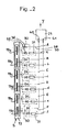
- each door edge receives an antenna 19, 20, split into several independent sections, for example into six sections 19 a, at 19 f (FIG. 2).
- These antenna sections receive only the waves reflected by certain bodies and especially the waves radiated by others, which are more or less coupled to the earth or which restore part of their induced voltage.
- this foreign body radiates or reflects a field of higher value, which then modifies the reception intensity of this antenna section and of its output signal, the more strongly the closer the foreign body is.
- the output signals can obviously be adjusted to a predetermined value so that, in the absence of foreign bodies, they are all equal.
- the signal is presented to two logic gates 23, 24 (FIG. 1) like triggers adjusted to different thresholds, the first commanding through a delay circuit 25 a relay 26 for blocking the doors, while the other also controls, through a delay circuit 27, the relay 28 for reopening the doors.
- a timed circuit 29 detects the persistence of the blocking or reopening commands beyond a preset time and activates an alarm.
- the antenna sections are connected to means for sampling two separate signals in relation, one with the peak value of the voltage induced on the section whose voltage is the most. the other with the average value of the voltages of all the sections, as well as with means for comparing these two signals.
- these sampling and analysis means comprise, first of all rectifying means 36, 37, positive and negative half-waves of the alternating signal which it receives, such as diodes.
- All the circuits 38 of the first signals which therefore come from positive half-waves, are connected to one of the inputs 40 of a comparator 21 such as an operational amplifier and this under the control of a gate 30 (FIG. 2), in order to effectively send to this input only the value of the first signal A, or B, or C, or D, or E, or F coming from the section whose voltage is the highest.
- a comparator 21 such as an operational amplifier
- circuits 39 of the second signals which originate from negative half-waves are connected to the other input 41 of the comparator 21 under the control of a limiter 31 such as a resistor, in order to effectively send only this input to this input.
- a limiter 31 such as a resistor
- the comparator then adds these two distinct signals and, during the initial adjustment mentioned above, which is carried out in the absence of a foreign body, the signals A and F and a to f of antenna sections being adjusted to be all identical, the detections on the positive and negative half-waves balance and the output signal Y is zero.
- the door 30 is formed by the diodes 36 which in known manner allow only the peak value to pass, provided that they are not otherwise, due to their connection by their bases, blocked by a higher signal from another diode.
- the output signal Y of the comparator 21 has the advantage of being accentuated and above all, when the balance is achieved, of being very little influenced by external operating conditions, resulting in high detection stability.
- the metal screen is produced by a U-shaped profile covering the edge of the door panel or the upright and carrying externally a strip 32, 33 hollowed out to accommodate the antenna and then closed at its front part by a plate 34, 35 permeable to waves.
- the strips 32, 33 housing the antennas of the two panels of a door are less than half the width of that of the screen and are offset with respect to each other: they therefore each adjoin one of the faces of the panel and are placed one next to the other in the closed door position.
Landscapes
- Physics & Mathematics (AREA)
- Electromagnetism (AREA)
- General Physics & Mathematics (AREA)
- Engineering & Computer Science (AREA)
- Remote Sensing (AREA)
- Life Sciences & Earth Sciences (AREA)
- General Life Sciences & Earth Sciences (AREA)
- Geology (AREA)
- Environmental & Geological Engineering (AREA)
- Geophysics (AREA)
- Geophysics And Detection Of Objects (AREA)
- Radar Systems Or Details Thereof (AREA)
- Elevator Door Apparatuses (AREA)
- Power-Operated Mechanisms For Wings (AREA)
- Switches That Are Operated By Magnetic Or Electric Fields (AREA)
- Electronic Switches (AREA)
- Control Of Vending Devices And Auxiliary Devices For Vending Devices (AREA)
- Indicating And Signalling Devices For Elevators (AREA)
Priority Applications (1)
| Application Number | Priority Date | Filing Date | Title |
|---|---|---|---|
| AT80400376T ATE8302T1 (de) | 1979-03-28 | 1980-03-20 | Naeherungsdetektor und dessen verwendung. |
Applications Claiming Priority (2)
| Application Number | Priority Date | Filing Date | Title |
|---|---|---|---|
| FR7908410A FR2452720A1 (fr) | 1979-03-28 | 1979-03-28 | Detecteur de proximite et element pourvu de ce detecteur |
| FR7908410 | 1979-03-28 |
Publications (2)
| Publication Number | Publication Date |
|---|---|
| EP0017547A1 EP0017547A1 (fr) | 1980-10-15 |
| EP0017547B1 true EP0017547B1 (fr) | 1984-07-04 |
Family
ID=9223909
Family Applications (1)
| Application Number | Title | Priority Date | Filing Date |
|---|---|---|---|
| EP19800400376 Expired EP0017547B1 (fr) | 1979-03-28 | 1980-03-20 | Détecteur de proximité et son utilisation |
Country Status (10)
| Country | Link |
|---|---|
| US (1) | US4326197A (enExample) |
| EP (1) | EP0017547B1 (enExample) |
| AT (1) | ATE8302T1 (enExample) |
| BR (1) | BR8001820A (enExample) |
| CA (1) | CA1148635A (enExample) |
| DE (1) | DE3068405D1 (enExample) |
| ES (1) | ES489970A1 (enExample) |
| FI (1) | FI70092C (enExample) |
| FR (1) | FR2452720A1 (enExample) |
| SU (1) | SU957774A3 (enExample) |
Cited By (1)
| Publication number | Priority date | Publication date | Assignee | Title |
|---|---|---|---|---|
| DE3445756A1 (de) * | 1983-12-14 | 1985-06-27 | Elevator GmbH, Baar | Verfahren und vorrichtung zur bilderzeugung |
Families Citing this family (6)
| Publication number | Priority date | Publication date | Assignee | Title |
|---|---|---|---|---|
| DE3114792C2 (de) * | 1981-04-11 | 1983-02-03 | Karl 7298 Loßburg Hehl | Schaltereinrichtung mit mehreren kontaktlosen Näherungsschaltern für Einzelfunktionen |
| FI70651C (fi) * | 1984-10-05 | 1986-09-24 | Kone Oy | Foerfarande och anordning foer oevervakning av omraodet framfoer en hissdoerr |
| GB8426010D0 (en) * | 1984-10-15 | 1984-11-21 | Memco Med Ltd | Automatic control |
| DE3632624C1 (de) * | 1986-09-25 | 1988-03-10 | Balluff Gebhard Feinmech | Stoerfeldunempfindlicher Naeherungsschalter |
| US6050369A (en) * | 1994-10-07 | 2000-04-18 | Toc Holding Company Of New York, Inc. | Elevator shaftway intrusion device using optical imaging processing |
| US5644111A (en) * | 1995-05-08 | 1997-07-01 | New York City Housing Authority | Elevator hatch door monitoring system |
Family Cites Families (16)
| Publication number | Priority date | Publication date | Assignee | Title |
|---|---|---|---|---|
| US2720284A (en) * | 1952-11-13 | 1955-10-11 | Otis Elevator Co | Elevator door control mechanism |
| US3018851A (en) * | 1957-11-19 | 1962-01-30 | Otis Elevator Co | Control mechanism for doors |
| FR1436069A (fr) * | 1965-03-12 | 1966-04-22 | Saxby | Détecteur de proximité |
| US3439358A (en) * | 1965-11-30 | 1969-04-15 | George Washington Ltd | Activity detectors |
| US3497995A (en) * | 1968-04-19 | 1970-03-03 | Stanley Works | Height sensitive proximity door operator system |
| US3496381A (en) * | 1968-05-10 | 1970-02-17 | Stanley Works | Proximity control guard plate |
| US3614724A (en) * | 1970-04-08 | 1971-10-19 | Atomic Energy Commission | Detection system |
| US3794992A (en) * | 1972-02-07 | 1974-02-26 | Gen Dynamics Corp | Radio frequency intrusion detection system |
| FR2173804B1 (enExample) * | 1972-03-03 | 1975-03-21 | Salmet Gaston | |
| US3846790A (en) * | 1973-06-08 | 1974-11-05 | Honeywell Inc | Intrusion detection systems |
| US3953770A (en) * | 1974-07-11 | 1976-04-27 | Jinnosuke Hayashi | Safety equipment for machinery used in processing plates, etc. |
| US3967261A (en) * | 1974-10-10 | 1976-06-29 | Fudaley Solly L | Proximity sensor with simultaneously active intermixed sensor types |
| US3973208A (en) * | 1975-02-14 | 1976-08-03 | Dovey Manufacturing Company | Capacitor detector device |
| GB1529862A (en) * | 1976-01-19 | 1978-10-25 | Thorn Domestic Appliances Ltd | Proximity switch |
| JPS5363582A (en) * | 1976-11-18 | 1978-06-07 | Mitsubishi Electric Corp | Proximity detector |
| JPS606280B2 (ja) * | 1977-03-24 | 1985-02-16 | 三菱電機株式会社 | 近接検出装置 |
-
1979
- 1979-03-28 FR FR7908410A patent/FR2452720A1/fr active Granted
-
1980
- 1980-03-20 EP EP19800400376 patent/EP0017547B1/fr not_active Expired
- 1980-03-20 DE DE8080400376T patent/DE3068405D1/de not_active Expired
- 1980-03-20 AT AT80400376T patent/ATE8302T1/de not_active IP Right Cessation
- 1980-03-21 CA CA000348083A patent/CA1148635A/en not_active Expired
- 1980-03-25 US US06/133,670 patent/US4326197A/en not_active Expired - Lifetime
- 1980-03-26 FI FI800932A patent/FI70092C/fi not_active IP Right Cessation
- 1980-03-26 BR BR8001820A patent/BR8001820A/pt not_active IP Right Cessation
- 1980-03-27 SU SU802906398A patent/SU957774A3/ru active
- 1980-03-27 ES ES489970A patent/ES489970A1/es not_active Expired
Cited By (1)
| Publication number | Priority date | Publication date | Assignee | Title |
|---|---|---|---|---|
| DE3445756A1 (de) * | 1983-12-14 | 1985-06-27 | Elevator GmbH, Baar | Verfahren und vorrichtung zur bilderzeugung |
Also Published As
| Publication number | Publication date |
|---|---|
| FI70092C (fi) | 1986-09-12 |
| ATE8302T1 (de) | 1984-07-15 |
| ES489970A1 (es) | 1980-10-01 |
| FR2452720B1 (enExample) | 1984-01-27 |
| SU957774A3 (ru) | 1982-09-07 |
| FR2452720A1 (fr) | 1980-10-24 |
| BR8001820A (pt) | 1980-11-18 |
| EP0017547A1 (fr) | 1980-10-15 |
| FI800932A7 (fi) | 1980-09-29 |
| CA1148635A (en) | 1983-06-21 |
| US4326197A (en) | 1982-04-20 |
| DE3068405D1 (en) | 1984-08-09 |
| FI70092B (fi) | 1986-01-31 |
Similar Documents
| Publication | Publication Date | Title |
|---|---|---|
| JP5283310B2 (ja) | 自動ドア周辺を検出するレーザ監視及び感知装置 | |
| FR2487554A1 (fr) | Appareil passif de detection infrarouge d'intrusions | |
| US20110108748A1 (en) | Evaluation of a difference signal between output signals of two receiving devices in a sensor apparatus | |
| FR2563646A1 (fr) | Appareil detecteur d'objets comprenant des photodetecteurs et destine a une zone de detection restreinte | |
| CN101641573A (zh) | 光学传感器芯片和具有这种传感器芯片的防夹装置 | |
| MXPA03005233A (es) | Sensor de deteccion de obstaculos que utiliza deteccion sincronica. | |
| BE1005734A5 (fr) | Procede et systeme de detection. | |
| US6271512B1 (en) | Optical system for detecting obstruction | |
| EP0017547A1 (fr) | Détecteur de proximité et son utilisation | |
| US7253890B2 (en) | Door obstacle sensor | |
| BE1028475B1 (fr) | Porte battante automatique et capteur | |
| BR9703893A (pt) | Barreira de luz para a reabertura de portas de elevador | |
| JP7549862B2 (ja) | 扉開閉用制御装置 | |
| US5703691A (en) | Integrated detector for laser remote sensors | |
| BE1005260A6 (fr) | Systeme de protection pour portes automatiques. | |
| EP1617030A2 (en) | Optical system for detecting an obstruction | |
| US5155354A (en) | Target detector capable of rejecting close-in objects | |
| KR100493982B1 (ko) | 개선된 잡음 허용 범위를 갖는 검출 시스템 | |
| BE1028378B1 (fr) | Porte automatique | |
| KR102826700B1 (ko) | 레이저 센서의 가변 수신 감도 제어 장치 및 방법 | |
| JP2871122B2 (ja) | 人体検知装置 | |
| JPH0412879B2 (enExample) | ||
| FR2469718A1 (fr) | Dispositif de detection d'un mouvement | |
| EP0380400A1 (fr) | Dispositif et procédé de contrôle électronique de sens de passage de clients dans l'entrée d'un magasin | |
| FR2746508A1 (fr) | Installation de detection par reflexion |
Legal Events
| Date | Code | Title | Description |
|---|---|---|---|
| PUAI | Public reference made under article 153(3) epc to a published international application that has entered the european phase |
Free format text: ORIGINAL CODE: 0009012 |
|
| AK | Designated contracting states |
Designated state(s): AT BE CH DE FR GB IT LU NL SE |
|
| 17P | Request for examination filed |
Effective date: 19810303 |
|
| ITF | It: translation for a ep patent filed | ||
| GRAA | (expected) grant |
Free format text: ORIGINAL CODE: 0009210 |
|
| AK | Designated contracting states |
Designated state(s): AT BE CH DE FR GB IT LU NL SE |
|
| REF | Corresponds to: |
Ref document number: 8302 Country of ref document: AT Date of ref document: 19840715 Kind code of ref document: T |
|
| REF | Corresponds to: |
Ref document number: 3068405 Country of ref document: DE Date of ref document: 19840809 |
|
| PLBE | No opposition filed within time limit |
Free format text: ORIGINAL CODE: 0009261 |
|
| STAA | Information on the status of an ep patent application or granted ep patent |
Free format text: STATUS: NO OPPOSITION FILED WITHIN TIME LIMIT |
|
| 26N | No opposition filed | ||
| ITTA | It: last paid annual fee | ||
| EPTA | Lu: last paid annual fee | ||
| EAL | Se: european patent in force in sweden |
Ref document number: 80400376.2 |
|
| PGFP | Annual fee paid to national office [announced via postgrant information from national office to epo] |
Ref country code: BE Payment date: 19950217 Year of fee payment: 16 |
|
| PGFP | Annual fee paid to national office [announced via postgrant information from national office to epo] |
Ref country code: AT Payment date: 19950228 Year of fee payment: 16 |
|
| PGFP | Annual fee paid to national office [announced via postgrant information from national office to epo] |
Ref country code: LU Payment date: 19950301 Year of fee payment: 16 |
|
| PGFP | Annual fee paid to national office [announced via postgrant information from national office to epo] |
Ref country code: GB Payment date: 19950310 Year of fee payment: 16 |
|
| PGFP | Annual fee paid to national office [announced via postgrant information from national office to epo] |
Ref country code: SE Payment date: 19950316 Year of fee payment: 16 |
|
| PGFP | Annual fee paid to national office [announced via postgrant information from national office to epo] |
Ref country code: CH Payment date: 19950323 Year of fee payment: 16 |
|
| PGFP | Annual fee paid to national office [announced via postgrant information from national office to epo] |
Ref country code: NL Payment date: 19950331 Year of fee payment: 16 |
|
| PGFP | Annual fee paid to national office [announced via postgrant information from national office to epo] |
Ref country code: DE Payment date: 19950425 Year of fee payment: 16 |
|
| PG25 | Lapsed in a contracting state [announced via postgrant information from national office to epo] |
Ref country code: LU Free format text: LAPSE BECAUSE OF NON-PAYMENT OF DUE FEES Effective date: 19960320 Ref country code: GB Effective date: 19960320 Ref country code: AT Effective date: 19960320 |
|
| PG25 | Lapsed in a contracting state [announced via postgrant information from national office to epo] |
Ref country code: SE Effective date: 19960321 |
|
| PG25 | Lapsed in a contracting state [announced via postgrant information from national office to epo] |
Ref country code: CH Effective date: 19960331 Ref country code: BE Effective date: 19960331 |
|
| BERE | Be: lapsed |
Owner name: SOC. LOGILIFT S.A.R.L. Effective date: 19960331 |
|
| PG25 | Lapsed in a contracting state [announced via postgrant information from national office to epo] |
Ref country code: NL Effective date: 19961001 |
|
| GBPC | Gb: european patent ceased through non-payment of renewal fee |
Effective date: 19960320 |
|
| REG | Reference to a national code |
Ref country code: CH Ref legal event code: PL |
|
| NLV4 | Nl: lapsed or anulled due to non-payment of the annual fee |
Effective date: 19961001 |
|
| PG25 | Lapsed in a contracting state [announced via postgrant information from national office to epo] |
Ref country code: DE Effective date: 19961203 |
|
| EUG | Se: european patent has lapsed |
Ref document number: 80400376.2 |
|
| REG | Reference to a national code |
Ref country code: FR Ref legal event code: CJ Ref country code: FR Ref legal event code: CA |
|
| REG | Reference to a national code |
Ref country code: FR Ref legal event code: CD |
|
| PGFP | Annual fee paid to national office [announced via postgrant information from national office to epo] |
Ref country code: FR Payment date: 19990224 Year of fee payment: 20 |