EP0017231A1 - Vertically movable centre board for a surf sail board - Google Patents
Vertically movable centre board for a surf sail board Download PDFInfo
- Publication number
- EP0017231A1 EP0017231A1 EP80101785A EP80101785A EP0017231A1 EP 0017231 A1 EP0017231 A1 EP 0017231A1 EP 80101785 A EP80101785 A EP 80101785A EP 80101785 A EP80101785 A EP 80101785A EP 0017231 A1 EP0017231 A1 EP 0017231A1
- Authority
- EP
- European Patent Office
- Prior art keywords
- sword
- plug
- arrangement according
- grooves
- side walls
- Prior art date
- Legal status (The legal status is an assumption and is not a legal conclusion. Google has not performed a legal analysis and makes no representation as to the accuracy of the status listed.)
- Granted
Links
- 238000007789 sealing Methods 0.000 claims description 3
- 230000005484 gravity Effects 0.000 description 13
- 238000006073 displacement reaction Methods 0.000 description 5
- XLYOFNOQVPJJNP-UHFFFAOYSA-N water Substances O XLYOFNOQVPJJNP-UHFFFAOYSA-N 0.000 description 4
- 230000009194 climbing Effects 0.000 description 2
- 238000007493 shaping process Methods 0.000 description 2
- 238000009966 trimming Methods 0.000 description 2
- 206010000496 acne Diseases 0.000 description 1
- 230000037396 body weight Effects 0.000 description 1
Images


Classifications
-
- B—PERFORMING OPERATIONS; TRANSPORTING
- B63—SHIPS OR OTHER WATERBORNE VESSELS; RELATED EQUIPMENT
- B63B—SHIPS OR OTHER WATERBORNE VESSELS; EQUIPMENT FOR SHIPPING
- B63B41/00—Drop keels, e.g. centre boards or side boards ; Collapsible keels, or the like, e.g. telescopically; Longitudinally split hinged keels
-
- B—PERFORMING OPERATIONS; TRANSPORTING
- B63—SHIPS OR OTHER WATERBORNE VESSELS; RELATED EQUIPMENT
- B63B—SHIPS OR OTHER WATERBORNE VESSELS; EQUIPMENT FOR SHIPPING
- B63B32/00—Water sports boards; Accessories therefor
- B63B32/60—Board appendages, e.g. fins, hydrofoils or centre boards
- B63B32/66—Arrangements for fixation to the board, e.g. fin boxes or foil boxes
Definitions
- the invention relates to a plug-in sword arrangement for a standing sail device with a sword box and a plug-in sword guided therein.
- a standing sail device essentially consists of a boat hull, a rig and a plug sword.
- the rig usually has a mast base with a joint, a mast, a boom and the sail.
- the mast track can be designed as a groove or blind hole or the like in the hull.
- the sword is usually arranged behind the mast, for which purpose a sword box is provided behind the mast track arranged in the longitudinal center plane, which forms a longitudinal slot going through the hull. The plug-in sword is pushed through this longitudinal slot and then protrudes downwards out of the hull.
- the control principle of the dock sail device is based on the shifting of the sail pressure point in relation to the Lateral center of gravity of the hull with a sword while sailing. Due to the articulated arrangement of the rig on the hull, the sail pressure point can be moved by tilting the mast forward or backward. In addition, several mast tracks arranged one behind the other can be provided, so that the sailor can choose the suitable mast track depending on the wind strength.
- the lateral center of gravity of the hull can be changed by adjusting the lateral center of gravity of the plug-in sword.
- folding swords can be used to a limited extent, which are tiltably mounted in the sword case and, by tilting backwards, shift the lateral center of gravity of the sword slightly to the rear. At the same time, however, the lateral center of gravity is also shifted upwards.
- a folding sword cannot guarantee the required stability because the lateral center of gravity cannot be shifted far enough to the rear and also moves upwards. The result of this is that the surfing device lurches in strong winds and high speeds, which leads to falls.
- the shaping of the hull efforts are made to choose the shape so that the hull forms the smallest possible wetted area very quickly and easily at higher speeds, ie rises very quickly out of the water. This possibility of shaping, however, is limited by the known sword arrangements.
- Another disadvantage is that the folding sword can not be placed vertically.
- the shift of the lateral center of gravity is not long enough, so that the surfing device not only lurches in strong winds, but also becomes very lucrative.
- the object of the invention is to provide a plug-in sword design for a standing sail device which enables an optimal lateral point adjustment of the plug-in sword, in particular for high speeds.
- a plug-in sword arrangement which consists of a sword box and a plug-in sword guided in the sword box, two in the side walls of the sword box genüberjif-ger.de, downward leading sack grooves are arranged and the plug-in sword has a horizontal axis running across the sword blade with protruding stumps, the stumps being inserted into the sack grooves when the sword is inserted and stored on the groove bottom, characterized in that the pocket grooves are connected to opposing longitudinal grooves arranged in the side walls. The stub axles from the pocket grooves can be inserted into these longitudinal grooves so that the plug-in sword can be moved in the longitudinal grooves in the longitudinal direction of the hull.
- detents for the axle journals are provided in the longitudinal grooves, so that the displacement of the plug-in sword can take place in sections.
- a folding sword known per se, which can be actuated with the foot, is preferably used as the plug-in sword.
- optimal trimming positions of the plug-in sword can be selected, the lateral center of gravity of the sword being able to be shifted both in the horizontal and in the vertical direction.
- the new plug-in sword arrangement ensures almost all trim positions between the center of gravity of the sail and the lateral center of gravity of the hull, which are necessary for the optimal control of the standing sail device.
- a telescopic sword is guided in the sword case, which can be pushed together and is also tiltably mounted in the sword case.
- the plug-in sword arrangement according to the invention is accommodated in a hull 1 of a standing sail device. Only the mast foot 2, which sits in the mast track 3, is indicated from the rig of the standing sail device. Further mast tracks 3 can of course be provided in the hull 1, so that mast displacement in the longitudinal direction of the hull is possible.
- the plug-in sword arrangement consists of the sword box 4 and the plug-in sword 5.
- the plug-in sword 5 is shown as a folding sword and, in a manner known per se, has the swivel and plug-in axis 6 arranged transversely to the plane of the sword surface with the two stub axles 7, 8. Over the thru axle 6 are on both sides of the sword surfaces brake plugs 9 arranged to produce a frictional connection with the side walls of the sword case in a conventional manner.
- Three cusps 10 are preferably formed on the sword head, which serve for the foot adjustment of the tilting position of the folding sword. 1 and 3, the possibility of tipping is indicated by the bow arrow. Folding swords of the type shown are known and are therefore not an immediate subject of the invention.
- the new plug-in sword arrangement can also be equipped with other types of swords and types of sword, provided that a plug-in axle 6 with stub axles 7.5 and preferably at least one brake plug or similar friction-generating device is provided.
- the length L is longer than the sword width B (Fig. 3). It is preferably longer than twice the width of the sword B. This measure makes it possible to move the sword in the sword case in the longitudinal direction of the hull.
- the sword case 4 consists of the two side walls 11_, 12 and the front wall 13 and the rear wall 14.
- the design and shape of the front and rear walls of the sword case depend in a manner known per se on the shape of the edge of the sword. It is therefore not discussed in more detail in the context of the present invention.
- the sword case forms the slot 15 with the upper slot opening 16 and the lower slot opening 17.
- a friction lining is expediently provided on the inside, which with the Brake plug 9 interacts in such a way that the respective set position of the sword 5 in the sword case 4 is maintained when sailing.
- pimples 18 or similar locking means for brake plugs or the like can be arranged on the inner surfaces of the side walls 11, 12, which lock the respective position of the gradual pivoting and / or displacement of the plug-in sword.
- the longitudinal displacement of the sword 5 in the sword box 4 is ensured by longitudinal grooves 19.2G.
- the grooves 19, 20 are spatially opposite one another in the sword case 4 and run in the longitudinal direction of the hull.
- the height of each groove is preferably only slightly larger than the height or diameter of the stub axles 7, 8, so that the stub axles can be guided in the longitudinal direction in the grooves.
- the depth of the grooves corresponds to the length of the stub axles 7, 8, so that the displacement of the plug-in sword is not hindered.
- the longitudinal grooves 19, 20 are each connected to a plug-in groove 21, 22, the grooves 20, 21 and 19 and 22 merge into one another, and the plug-in grooves 21, 22 have approximately the same dimensions as the longitudinal grooves 19, 20.
- the plug-in grooves 21, 22 run vertically downward from the slot opening 16 until they meet the longitudinal grooves 19, 20 at right angles.
- another impact angle can also be selected, ie, for example, the longitudinal grooves can have an inclination to the horizontal and / or the plug-in grooves can have an inclination to the vertical (not shown).
- the plug-in grooves 21, 22 are expediently arranged behind the longitudinal grooves 19, 20 (not shown), the front wall 13 being so far from the foremost locking means 24 It is distant that the head of the folding sword can be swung forward unhindered and the function of the folding sword z. B. is not hindered on the beach.
- plug-in grooves 21, 22 can also be advantageous to provide the plug-in grooves 21, 22 in the middle or at the end or at any other point on the sword case.
- more than one pair of slots 21, 22 can be accommodated in the side walls 11, 12 of the sword case 4 (not shown).
- the lateral center of gravity of the sword can be easily shifted upwards. If a telescopic retractable sword is also used as the sword, the lateral point adjustment is particularly possible.
- locking recesses 24 can be arranged in the bottom wall 23 of each longitudinal groove 19, 20, into which the stub axles 7, 8 can be inserted.
- the sword is 5 single for transfer Lich pulled up a bit until the stub axles 7,8 come under the top wall 25 of the longitudinal grooves 19,20. Then the sword is pushed forward or backward in the longitudinal grooves.
- a sword 26 or the like, which is known per se, is preferably used to actuate the sword 5, which is only indicated in FIGS. 1 and 3 and is not shown in the other figures, in order not to disturb the clarity of the drawing.
- the shape of the locking recesses 24 is preferably based on the shape of the stub axles 7, 8.
- the locking recesses are cup-shaped, so that they serve as rotary bearings for the round axle journals 7, 8.
- tilting or pivoting of the sword 5 in the sword case 4 is to be prevented, for example square stub axles and recesses can be selected so that the respectively selected position of the sword is locked.
- the friction linings or knobs 18 and the brake plugs 9 could possibly be omitted.
- the lower slot opening 17 is closed with preferably two elastic, opposite and overlapping sealing lips 27 arranged on the sword case, for example made of rubber or plastic.
- the sword 5 is inserted through the sealing lips 27, the lips being so elastic, but also so firm, that they nestle against the sword on the one hand and on the other hand in the areas that only cover the opening 17, prevent that when sailing Splashes of water from the sword box.
- the invention includes a considerable improvement in the maneuverability and trimming possibility of a stand sailing device. Above all, it also makes it possible to optimize the hull shape in terms of sliding and climbing, which was previously pointless due to the lack of trim options.
Landscapes
- Chemical & Material Sciences (AREA)
- Engineering & Computer Science (AREA)
- Combustion & Propulsion (AREA)
- Mechanical Engineering (AREA)
- Ocean & Marine Engineering (AREA)
- Toys (AREA)
- Structures Of Non-Positive Displacement Pumps (AREA)
- Braking Arrangements (AREA)
Abstract
Description
Die Erfindung betrifft eine Steckschwertanordnung für ein Stehsegelgerät mit einem Schwertkasten und einem darin geführten Steckschwert.The invention relates to a plug-in sword arrangement for a standing sail device with a sword box and a plug-in sword guided therein.
Ein Stehsegelgerät besteht im wesentlichen aus einem Bootskörper, einem Rigg und einem Steckschwert. Das Rigg weist in der Regel einen Mastfuß mit Gelenk, einen Mast, einen Gabelbaum und das Segel auf. Zum Windsurfen werden das Rigg in die sogenannte Mastspur und das Steckschwert in den Schwertkasten gesteckt, wobei der Mastfuß zusammen mit der Mastspur für die jederzeit wieder lösbare Verbindung des Riggs vom Bootskörper sorgt. Die Mastspur kann je nach Ausgestaltung des Mastfußes als Nut oder Sackloch oder dergleichen im Bootskörper ausgebildet sein. Das Steckschwert ist in der Regel hinter dem Mast angeordnet, wozu hinter der in der Längsmittenebene angeordneten Mastspur ein Schwertkasten vorgesehen ist, der einen durch den Bootskörper gehenden Längsschlitz bildet. Durch diesen Längsschlitz wird das Steckschwert geschoben und ragt dann aus dem Bootskörper nach unten heraus.A standing sail device essentially consists of a boat hull, a rig and a plug sword. The rig usually has a mast base with a joint, a mast, a boom and the sail. For windsurfing, the rig is placed in the so-called mast track and the plug-in sword in the sword case, whereby the mast base together with the mast track ensures that the rig can be detached from the hull at any time. Depending on the design of the mast base, the mast track can be designed as a groove or blind hole or the like in the hull. The sword is usually arranged behind the mast, for which purpose a sword box is provided behind the mast track arranged in the longitudinal center plane, which forms a longitudinal slot going through the hull. The plug-in sword is pushed through this longitudinal slot and then protrudes downwards out of the hull.
Das Steuerungsprinzip des Stegsegelgeräts beruht auf der Verlegung des Segeldruckpunkts in bezug auf den Lateralschwerpunkt des Bootskörpers mit Schwert während des Segelns. Der Segeldruckpunkt kann aufgrund der gelenkigen Anordnung des Riggs auf dem Bootskörper durch Neigung des Masts nach vorn oder hinten verlegt werden. Zudem können mehrere hintereinander angeordnete Mastspuren vorgesehen sein, so daß der Segler in Abhängigkeit von der Windstärke die geeignete Mastspur wählen kann. Der Lateralschwercunkt des Bootskörpers ist durch die Verstellung des Lateralschwerpunktes des Steckschwertes veränderbar. Zu diesem Zweck können in begrenztem Umfang Klappschwerter benutzt werden, die im Schwertkasten kippbar gelagert sind und durch das Kippen nach hinten den Lateralschwerpunkt des Schwerts geringfügig nach achtern verlagern. Gleichzeitig wird aber auch der Lateralschwerpunkt nach oben versetzt.The control principle of the dock sail device is based on the shifting of the sail pressure point in relation to the Lateral center of gravity of the hull with a sword while sailing. Due to the articulated arrangement of the rig on the hull, the sail pressure point can be moved by tilting the mast forward or backward. In addition, several mast tracks arranged one behind the other can be provided, so that the sailor can choose the suitable mast track depending on the wind strength. The lateral center of gravity of the hull can be changed by adjusting the lateral center of gravity of the plug-in sword. To this end, folding swords can be used to a limited extent, which are tiltably mounted in the sword case and, by tilting backwards, shift the lateral center of gravity of the sword slightly to the rear. At the same time, however, the lateral center of gravity is also shifted upwards.
Obwohl es mit diesen bekannten Variationsmöglichkeiten der Veränderbarkeit der Schwerpunkte gelungen ist, das Stehsegelgerät in engen Grenzen zu trimmen, reichen diese Mittel insbesondere beim Starkwindsegeln bei weitem noch nicht aus. Insbesondere kann nachteilig sein, daß durch das Kippen des Klappschwerts der Lateralschwerpunkt nach oben wandert. Bei Starkwind und schneller Fahrt wird nämlich der Bug des Bootskörpers weit aus dem Wasser gehoben, so daß die benetzte Fläche des Bootskörpers erheblich kleiner wird. Dies ist erwünscht, weil dadurch der Fahrtwiderstand des Bootskörpers verringert wird und somit höhere Geschwindigkeiten erzielt werden können. Dabei ist der Segler jedoch gezwungen, sich sehr weit nach hinten zu stellen, um das Surfgerät dirigieren und das Steigen begünstigen zu können. Die Verlagerung des Körpergewichts des Seglers erfordert eine erhöhte Stabilität des Surfbretts in bezug auf den dynamischen Druck des Wassers auf das Schwert. Ein Klappschwert kann die erforderliche Stabilität nicht gewährleisten, weil der Lateralschwerpunkt nicht weit genug nach achtern verlagert werden kann und außerdem nach oben wandert. Die Folge davon ist, daß das Surfgerät bei Starkwind und hohen Geschwindigkeiten schlingert, was zu Stürzen führt. Man ist jedoch bei der Formgebung des Bootskörpers bestrebt, die Form so zu wählen, daß der Bootskörper bei höheren Geschwindigkeiten sehr schnell und leicht eine möglichst kleine benetzte Fläche bildet, d. h. sehr schnell aus dem Wasser steigt. Dieser Möglichkeit der Formgebung sind jedoch mit den bekannten Schwertanordnungen die oben angegebenen Grenzen gesetzt. Nachteilig ist ferner, daß das Klappschwert nicht senkrecht gestellt werden kann. Hinzukommt, daß der Verlagerungsweg des Lateralschwerpunktes nicht lang genug ist, so daß das Surfgerät bei Starkwind nicht nur schlingert, sondern auch sehr luvgierig wird.Although it has been possible to trim the standing sail device within narrow limits with these known variation possibilities of changing the focal points, these means are still far from sufficient, especially when sailing in strong winds. In particular, it can be disadvantageous that the lateral center of gravity moves upward as a result of the tilting of the folding sword. With strong wind and fast driving, the bow of the hull is raised far out of the water, so that the wetted area of the hull becomes considerably smaller. This is desirable because it reduces the drag of the hull and therefore higher speeds can be achieved. However, the sailor is forced to stand very far back in order to be able to direct the surfing device and promote climbing. The shift in the body weight of the sailor requires increased stability of the surfboard in in relation to the dynamic pressure of water on the sword. A folding sword cannot guarantee the required stability because the lateral center of gravity cannot be shifted far enough to the rear and also moves upwards. The result of this is that the surfing device lurches in strong winds and high speeds, which leads to falls. However, in the shaping of the hull, efforts are made to choose the shape so that the hull forms the smallest possible wetted area very quickly and easily at higher speeds, ie rises very quickly out of the water. This possibility of shaping, however, is limited by the known sword arrangements. Another disadvantage is that the folding sword can not be placed vertically. In addition, the shift of the lateral center of gravity is not long enough, so that the surfing device not only lurches in strong winds, but also becomes very lucrative.
Aufgabe der Erfindung ist, eine Steckschwertancrdnung für ein Stehsegelgerät zu schaffen, die eine optimale Lateralpunktsverstellung des Steckschwerts insbesondere für hohe Geschwindigkeiten ermöglicht.The object of the invention is to provide a plug-in sword design for a standing sail device which enables an optimal lateral point adjustment of the plug-in sword, in particular for high speeds.
Diese Aufgabe wird durch eine Steckschwertanordnung gelöst, die aus einem Schwertkasten und einem im Schwertkasten geführten Steckschwert besteht, wobei in den Seitenwänden des Schwertkastens zwei sich ge- genüberjif-ger.de, nach unten fuhrende Sacknuten angeordnet sind urd das Steckschwert eine quer durch das Schwertblatt gehende horizontale Achse mit überstehenden Achsstümpfen aufweist, wobei die Achsstümpfe beim Stecken des Schwertes in die Sacknuten eingeführt werden und auf dem Nutboden lagern, dadurch gekennzeichnet, daß die Sacknuten mit in den Seitenwänden angeordneten, sich gegenüberliegenden Längsnuten in Verbindung stehen. In diese Längsnuten können die Achsstumpfe aus den Sacknuten eingeführt werden, so daß das Steckschwert in den Längsnuten in Längsrichtung des Bootskörpers versetzt werden kann. Nach einer besonderen Ausführungsform der Erfindung sind in den Längsnuten Rastungen für die Achszapfen vorgesehen, so daß die Versetzung des Steckschwertes abschnittsweise erfolgen kann. Als Steckschwert wird vorzugsweise ein an sich bekanntes Klappschwert verwendet, das mit dem Fuß betätigbar ist. Durch eine derartige Steckschwertanordnung können optimale Trimmstellungen des Steckschwertes gewählt werden, wobei der Lateralschwerpunkt des Schwertes sowohl in horizontaler als auch in vertikaler Richtung verlagert werden kann. In Kombination mit mehreren Mastspuren gewährleistet die neue Steckschwertanordnung nahezu alle Trimmstellungen zwischen dem Segelschwerpunkt und dem Lateralschwerpunkt des Bootskörpers, die für die optimale Aussteuerung des Stehsegelgerätes erforderlich sind.This object is achieved by a plug-in sword arrangement which consists of a sword box and a plug-in sword guided in the sword box, two in the side walls of the sword box genüberjif-ger.de, downward leading sack grooves are arranged and the plug-in sword has a horizontal axis running across the sword blade with protruding stumps, the stumps being inserted into the sack grooves when the sword is inserted and stored on the groove bottom, characterized in that the pocket grooves are connected to opposing longitudinal grooves arranged in the side walls. The stub axles from the pocket grooves can be inserted into these longitudinal grooves so that the plug-in sword can be moved in the longitudinal grooves in the longitudinal direction of the hull. According to a special embodiment of the invention, detents for the axle journals are provided in the longitudinal grooves, so that the displacement of the plug-in sword can take place in sections. A folding sword known per se, which can be actuated with the foot, is preferably used as the plug-in sword. With such a plug-in sword arrangement, optimal trimming positions of the plug-in sword can be selected, the lateral center of gravity of the sword being able to be shifted both in the horizontal and in the vertical direction. In combination with several mast tracks, the new plug-in sword arrangement ensures almost all trim positions between the center of gravity of the sail and the lateral center of gravity of the hull, which are necessary for the optimal control of the standing sail device.
Nach einer weiteren Ausführungsform der Erfindung wird im Schwertkasten ein Teleskopschwert geführt, das in sich zusammenschiebbar und zudem kippbar im Schwertkasten gelagert ist. Weitere erfindungswesentliche Merkmale sind Gegenstand der Ansprüche 2 bis 19.According to a further embodiment of the invention, a telescopic sword is guided in the sword case, which can be pushed together and is also tiltably mounted in the sword case. Further features essential to the invention are the subject of
Aus der US-PS 2 466 006 ist zwar ein Schwertkasten für ein Segelboot bekannt, auf dem Rastungen für Achsstümpfe des Schwertes vorgesehen sind, die Rastungen dienen jedoch lediglich dazu, die Kippstellung des Schwertes zu gewährleisten. Eine Versetzung des Schwertes in Längsrichtung des Schwertkastens ist nicht möglich.From US-
Anhand der Zeichnung wird die Erfindung beispielhaft näher erläutert. Es zeigen:
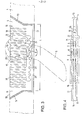
- Fig. 1 schematisch die Anordnung des Schwertkastens mit Schwert im Bootskörper von der Seite,
- Fig. 2 die Anordnung des Schwertkastens mit Schwert im Bootskörper von vorn,
- Fig. 3 einen Schnitt durch den Schwertkasten,
- Fig. 4 eine Draufsicht auf den Schwertkasten,
- Fig. 5 eine perspektivische Darstellung des Schwertkastens mit Schwert teilweise im Schnitt.
- 1 schematically shows the arrangement of the sword case with sword in the hull from the side,
- 2 shows the arrangement of the sword case with sword in the hull from the front,
- 3 shows a section through the sword box,
- 4 is a plan view of the sword case,
- Fig. 5 is a perspective view of the sword box with sword partially in section.
Die erfindungsgemäße Steckschwertanordnung ist in einem Bootskörper 1 eines Stehsegelgeräts untergebracht. Vom Rigg des Stehsegelgeräts ist lediglich der Mastfuß 2 angedeutet gezeichnet, der in der Mastspur 3 sitzt. Im Bootskörper 1 können selbstverständlich weitere Mastspuren 3 vorgesehen sein, so daß die Mastversetzung in Längsrichtung des Bootskörpers möglich ist.The plug-in sword arrangement according to the invention is accommodated in a
Die Steckschwertanordnung besteht aus dem Schwertkasten 4 und dem Steckschwert 5. Das Steckschwert 5 ist als Klappschwert dargestellt und weist in an sich bekannter Weise die quer zur Schwertflächenebene angeordnete Schwenk-und Steckachse 6 mit den beiden Achsstümpfen 7, 8 auf. Über der Steckachse 6 sind beidseitig auf den Schwertflächen Bremsstopfen 9 angeordnet, die in an sich bekannter Weise mit den Seitenwänden des Schwertkastens einen Reibschluß erzeugen sollen. Auf dem Schwertkopf sind vorzugsweise drei Höcker 10 ausgebildet, die für die Fußverstellung der Kipplage des Klappschwertes dienen. In Fig. 1 und 3 ist die Möglichkeit des Kippens durch den Bogenpfeil angedeutet. Klappschwerter der dargestellten Art sind bekannt und daher nicht unmittelbarer Gegenstand der Erfindung.The plug-in sword arrangement consists of the
Die neue Steckschwertanordnung kann auch mit anderen Schwertformen und Schwertarten bestückt werden, sofern eine Steckachse 6 mit Achsstümpfen 7,5 und vorzugsweise mindestens einem Bremsstopfen oder dergleichen Reibung erzeugende Vorrichtung vorgesehen sind.The new plug-in sword arrangement can also be equipped with other types of swords and types of sword, provided that a plug-in
Wesentlich und neu ist, daß der Schwertkasten 4 länger als üblich ausgeführt ist. Die Länge L ist länger als die Schwertbreite B (Fig. 3 ). Sie ist vorzugsweise länger als die doppelte Schwertbreite B. Durch diese Maßnahme wird die Möglichkeit geschaffen, das Schwert im Schwertkasten in Längsrichtung des Bootskörpers zu versetzen.It is essential and new that the
Der Schwertkasten 4 besteht aus den beiden Seitenwänden 11_,12 sowie der Vorderwand 13 und der Rückwand 14. Die Ausgestaltung und Form der Vorder- und Rückwand des Schwertkastens richtet sich in an sich bekannter Weise nach der Kantenform des Steckschwertes. Es wird deshalb im Rahmen der vorliegenden Erfindung nicht näher darauf eingegangen. Der Schwertkasten bildet den Steckschlitz 15 mit der oberen Schlitzöffnung 16 und der unteren Schlitzöffnung 17. Auf den beiden Seitenwänden 11 und 12 ist zweckmäßigerweise innenseitig ein Reibbelag vorgesehen, der mit dem Bremsstopfen 9 derart zusammenwirkt, daß die jeweilige eingestellte Stellung des Schwertes 5 im Schwertkasten 4 beim Segeln erhalten bleibt. Vorzugsweise können zusätzlich zum Reibbelag Noppen 18 oder dergleichen Rastmittel für Bremsstopfen oder dergleichen auf den Innenflächen der Seitenwände 11, 12 angeordnet sein, die die jeweilige Stellung der stufenweisen Verschwenkung und/oder Versetzung des Steckschwertes arretieren.The
Nach der Erfindung wird die Längsversetzung des Steckschwertes 5 im Schwertkasten 4 durch Längsnuten 19,2G gewährleistet. Die Nuten 19,20 liegen sich räumlich im Schwertkasten 4 gegenüber und verlaufen in Längsrichtung des Bootskörpers. Die Höhe jeder Nut ist vorzugsweise lediglich etwas größer als die Höhe oder der Durchmesser der Achsstümpfe 7, 8, so daß die Achsstümpfe in den Nuten in Längsrichtung geführt werden können. Die Tiefe der Nuten entspricht der Länge der Achsstümpfe 7, 8, so daß die Versetzung des Steckschwertes nicht behindert wird. Die Längsnuten 19,20 stehen je mit einer Stecknut 21,22 in Verbindung, wobei die Nuten 20,21 sowie 19 und 22 ineinander übergehen, und wobei die Stecknuten 21, 22 etwa die gleichen Abmessungen aufweisen wie die Längsnuten 19,20. Im dargestellten Beispiel verlaufen die Stecknuten 21,22 senkrecht von der Schlitzöffnung 16 nach unten, bis sie rechtwinklig auf die Längsnuten 19,20 treffen. Selbstverständlich kann aber auch ein anderer Auftreffwinkel gewählt werden, d.h. es können beispielsweise die Längsnuten eine Neigung zur Horizontalen und/oder die Stecknuten eine Neigung zur Vertikalen aufweisen (nicht dargestellt). Die Stecknuten 21, 22 sind zweckmäßigerweise hinter den Längsnuten 19, 20 angeordnet (nicht dargestellt), wobei die Vorderwand 13 so weit vom vordersten Rastmittel 24 entfernt ist, daß der Kopf des Klappschverts ungehindert nach vorn geschwenkt werden kann und die Funktion des Klappschwerts beim Auflaufen z. B. auf den Strand nicht behindert wird. Es kann aber auch vorteilhaft sein, die Stecknuten 21, 22 in der Mitte oder am Ende oder an einer anderen beliebigen Stelle des Schwertkastens vorzusehen. Vorzugsweise können mehr als ein Stecknutenpaar 21, 22 in den Seitenwänden 11, 12 des Schwertkastens 4 untergebracht sein (nicht dargestellt). Es kann außerdem zweckmäßig sein, mehrere Längsnutenpaare 19,20 übereinarderliegend vorzusehen, sc daß das Steckschwert wahlweise durch mehrere Stecknutenpaare 21,22 eingesetzt und/oder in mehreren Längsnutenpaaren 19,20 in Längsrichtung des Bootskörpers versetzt werder, kann. Durch die Anordnung mehrerer Längsnutenpaare 19,20 übereinander kann die Schwertfläche, die aus dem Bootskörper nach unten herausragt, verkleinert werden. In Verbindung mit einem Schwertkcpf, der in der untersten Stellung nicht aus dem Schwertkasten nach eben herausragt, sondern die Schlitzöffnung 16 erst geringfügig überragt, wenn er in der obersten Nut geführt wird, kann der Lateralschwerpunkt des Schwertes auf einfache Weise nach oben verlagert werden. Wenn als Schwert darüber hinaus ein teleskopartig einfahrbares Schwert verwendet wird, ist die Lateralpunktsverstellung besonders optimal möglich.According to the invention, the longitudinal displacement of the
Nach einer weiteren Ausführungsform der Erfindung können in der Unterwand 23 jeder Längsnut 19,20 Rastvertiefungen 24 angeordnet sein, in die die Achsstümpfe 7,8 eingesetzt werden können. Auf diese Weise wird die jeweils gewählte Stellung des Steckschwertes festgelegt. Zur Versetzung wird das Schwert 5 lediglich ein Stück hochgezogen, bis die Achsstümpfe 7,8 unter die Oberwand 25 der Längsnuten 19,20 stoßen. Dann wird das Schwert in den Längsnuten nach vorn oder hinten geschoben. Zur Betätigung des Schwertes 5 dient vorzugsweise eine an sich bekannte Schlaufe 26 oder dergleichen, die lediglich in Fig. 1 und 3 angedeutet gezeichnet und in den anderen Fig. nicht dargestellt ist, um die Übersichtlichkeit der Zeichnung nicht zu stören.According to a further embodiment of the invention, locking recesses 24 can be arranged in the
Die Form der Rastvertiefungen 24 richtet sich vorzugsweise nach der Form der Achsstümpfe 7,8. Im dargestellten Fall sind die Rastvertiefungen schalenförmig ausgebildet, so daß sie für die runden Achszapfen 7,8 als Drehlager dienen. Soll jedoch ein Kippen oder Verschwenken des Schwertes 5 im Schwertkasten 4 verhindert werden, können beispielsweise viereckige Achsstümpfe und Rastvertiefungen gewählt werden, so daß die jeweils gewählte Stellung des Schwertes arretiert ist. In diesem Fall könnten ggf. die Reibbeläge oder Noppen 18 und die Bremsstopfen 9 entfallen.The shape of the locking recesses 24 is preferably based on the shape of the
Besonders vorteilhaft ist, wenn die untere Schlitzöffnung 17 mit vorzugsweise zwei elastischen, sich gegenüberliegenden und sich überlappenden, am Schwertkasten angeordneten Dichtlippen 27 beispielsweise aus Gummi oder Kunststoff verschlossen ist. Durch die Dichtlippen 27 wird das Schwert 5 gesteckt, wobei die Lippen so elastisch, aber auch so fest sein sollen, - daß sie sich einerseits an das Schwert anschmiegen und andererseits in den Bereichen, die lediglich die Öffnung 17 abdecken, verhindern, daß beim Segeln Wasser aus dem Schwertkasten hochspritzt.It is particularly advantageous if the
Mit der Erfindung ist es gelungen, eine Möglichkeit zu schaffen, die Schwertstellung optimal den Trimmerfordernissen beim Segeln anzupassen. Da zudem auch ein Klappschwert im neuen Schwertkasten geführt werden kann, ergeben sich gleichzeitig die bekannten Vorteile des Klappschwertes. Darüber hinaus ist es aber auch möglich geworden, insbesondere das Klappschwert nicht nur nach hinten zu kippen, sondern auch senkrecht stellen zu können, was bisher nicht gegeben war. Man kann mit der erfindungsgemäßen Steckschwertanordnung sogar über die senkrechte Stellung hinaus eine nach vorn gekippte Stellung des Steckschwertes wählen, was in bestimmten Fällen von Vorteil sein kann. Insgesamt sind die möglichen Stellungen des Steckschwertes so vielfältig wählbar, daß nahezu alle erforderlichen Trir-nstellungen eingestellt werden können, um z. B. die Luvgierigkeit des Stehsegelgeräts bei Starkwind zu kompensieren oder die Wendigkeit zu verbessern oder das Schwert bei allen Wind- und Seegangbedingungen unter der Bedienungsperson anordnen zu können und damit das Schlingern auszuschließen. In Verbindung mit einem Klappschwert oder Teleskopschwert bleiben somit keine Trimmprobleme mehr unlösbar. Zusätzlich kann man sogar auf der Oberkante des Schwertkastens Markierungen anordnen, die eine Empfehlung der Schwertstellung in Abhängigkeit von der Windstärke beinhalten. Durch die Wahl einer besonders großen Länge des Schwertkastens und damit durch die Möglichkeit der sehr weiten Verstellung des Steckschwerts in Längsrichtung des Bootskörpers wird nicht nur Gewicht am Bootskörper eingespart, sondern es kann sich auch erübrigen, mehrere Mastspuren zur Verlegung des Segelschwerpunktes vorzusehen. Die Erfindung beinhaltet insofern eine erhebliche Verbesserung der Manövrierfähigkeit und Trimmöglichkeit eines Stehsegelgerätes. Sie macht es vor allem aber auch möglich, die Bootskörperform in bezug auf das Gleiten und Steigen zu optimieren, was bisher wegen der fehlenden Trimmöglichkeiten zwecklos war.With the invention it has been possible to create a possibility of optimally adapting the sword position to the trimmer requirements when sailing. Since a folding sword can also be carried in the new sword case, the well-known advantages of the folding sword also result. In addition, it has also become possible not only to tilt the folding sword backwards, but also to be able to position it vertically, which was not previously the case. With the plug-in sword arrangement according to the invention, a position of the plug-in sword which is tilted forward is even selected beyond the vertical position, which can be advantageous in certain cases. All in all, the possible positions of the plug-in sword can be selected in so many different ways that almost all of the required trir-positions can be set, e.g. B. to compensate for the windwardness of the upright sailing device in strong winds or to improve maneuverability or to be able to arrange the sword under all operating conditions in all wind and sea conditions and thus to avoid lurching. In connection with a folding sword or telescopic sword, no more trim problems remain unsolvable. In addition, you can even place markings on the upper edge of the sword box, which contain a recommendation of the sword position depending on the wind strength. By choosing a particularly large length of the sword case and thus by the possibility of very wide adjustment of the sword in the longitudinal direction of the hull, not only is weight saved on the hull, but it can also be superfluous to provide several mast tracks for laying the center of gravity of the sail. In this respect, the invention includes a considerable improvement in the maneuverability and trimming possibility of a stand sailing device. Above all, it also makes it possible to optimize the hull shape in terms of sliding and climbing, which was previously pointless due to the lack of trim options.
Claims (19)
Priority Applications (1)
| Application Number | Priority Date | Filing Date | Title |
|---|---|---|---|
| AT80101785T ATE1639T1 (en) | 1979-04-09 | 1980-04-03 | PLUGBOARD ARRANGEMENT FOR A STAND-SAILING DEVICE. |
Applications Claiming Priority (2)
| Application Number | Priority Date | Filing Date | Title |
|---|---|---|---|
| DE2914220 | 1979-04-09 | ||
| DE2914220A DE2914220C3 (en) | 1979-04-09 | 1979-04-09 | Sword assembly for a sailboard |
Publications (2)
| Publication Number | Publication Date |
|---|---|
| EP0017231A1 true EP0017231A1 (en) | 1980-10-15 |
| EP0017231B1 EP0017231B1 (en) | 1982-10-13 |
Family
ID=6067814
Family Applications (1)
| Application Number | Title | Priority Date | Filing Date |
|---|---|---|---|
| EP80101785A Expired EP0017231B1 (en) | 1979-04-09 | 1980-04-03 | Vertically movable centre board for a surf sail board |
Country Status (3)
| Country | Link |
|---|---|
| EP (1) | EP0017231B1 (en) |
| AT (1) | ATE1639T1 (en) |
| DE (1) | DE2914220C3 (en) |
Cited By (4)
| Publication number | Priority date | Publication date | Assignee | Title |
|---|---|---|---|---|
| WO1990013472A1 (en) * | 1989-05-09 | 1990-11-15 | Zander Wolf Dietrich | Device for releasably fastening a fin shaft |
| EP0420444A1 (en) * | 1989-09-29 | 1991-04-03 | Bic Corporation | Daggerfin adjustable sailboard skeg |
| US5148761A (en) * | 1989-09-29 | 1992-09-22 | Bic Corporation | Daggerfin adjustable sailboard skeg |
| EP0515087A1 (en) * | 1991-05-21 | 1992-11-25 | Andrew Thomas Kinnaird | Fin box assemblies for windsurfers |
Families Citing this family (2)
| Publication number | Priority date | Publication date | Assignee | Title |
|---|---|---|---|---|
| DE3217444A1 (en) * | 1982-05-08 | 1983-11-10 | Schütz-Werke GmbH & Co KG, 5418 Selters | Centreboard mounting for windsurfing boards |
| DE3409157A1 (en) * | 1984-03-13 | 1985-09-19 | Hannes 8100 Garmisch-Partenkirchen Marker | SAILING BOARD |
Citations (5)
| Publication number | Priority date | Publication date | Assignee | Title |
|---|---|---|---|---|
| US2466006A (en) * | 1946-09-13 | 1949-04-05 | George J Danko | Adjustable centerboard |
| US4044416A (en) * | 1976-06-14 | 1977-08-30 | Brewer Charles A | Surfboard with adjustable fin |
| DE2659297A1 (en) * | 1976-12-29 | 1978-03-30 | Georg Buechl | Adjustable centre-board for wind-surfer - has pivoted mounting with friction pads to hold desired position and profiled top for foot operation |
| DE2706141A1 (en) * | 1977-02-14 | 1978-08-17 | Gerhard Ing Grad Winter | Pivoted centre-board for wind-surfer - has sprung friction hold in box insert with flexible adjusting cord |
| DE2738070A1 (en) * | 1977-08-24 | 1979-03-01 | Wolfgang Rehm | Safety mounting for steering board of wind-surfer - has pivotal mounting in slot with friction grip on each side for lifting up when running aground |
Family Cites Families (2)
| Publication number | Priority date | Publication date | Assignee | Title |
|---|---|---|---|---|
| US3659300A (en) * | 1969-07-25 | 1972-05-02 | W A V E Corp | Fin attachment structure for surfboards |
| FR2369150A1 (en) * | 1976-10-27 | 1978-05-26 | Louvet Noel | Wind surfing board with float - has hinged pivot point connecting base of mast to centre plate |
-
1979
- 1979-04-09 DE DE2914220A patent/DE2914220C3/en not_active Expired
-
1980
- 1980-04-03 EP EP80101785A patent/EP0017231B1/en not_active Expired
- 1980-04-03 AT AT80101785T patent/ATE1639T1/en not_active IP Right Cessation
Patent Citations (5)
| Publication number | Priority date | Publication date | Assignee | Title |
|---|---|---|---|---|
| US2466006A (en) * | 1946-09-13 | 1949-04-05 | George J Danko | Adjustable centerboard |
| US4044416A (en) * | 1976-06-14 | 1977-08-30 | Brewer Charles A | Surfboard with adjustable fin |
| DE2659297A1 (en) * | 1976-12-29 | 1978-03-30 | Georg Buechl | Adjustable centre-board for wind-surfer - has pivoted mounting with friction pads to hold desired position and profiled top for foot operation |
| DE2706141A1 (en) * | 1977-02-14 | 1978-08-17 | Gerhard Ing Grad Winter | Pivoted centre-board for wind-surfer - has sprung friction hold in box insert with flexible adjusting cord |
| DE2738070A1 (en) * | 1977-08-24 | 1979-03-01 | Wolfgang Rehm | Safety mounting for steering board of wind-surfer - has pivotal mounting in slot with friction grip on each side for lifting up when running aground |
Cited By (6)
| Publication number | Priority date | Publication date | Assignee | Title |
|---|---|---|---|---|
| WO1990013472A1 (en) * | 1989-05-09 | 1990-11-15 | Zander Wolf Dietrich | Device for releasably fastening a fin shaft |
| EP0420444A1 (en) * | 1989-09-29 | 1991-04-03 | Bic Corporation | Daggerfin adjustable sailboard skeg |
| US5038698A (en) * | 1989-09-29 | 1991-08-13 | Bic Corporation | Daggerfin adjustable sailboard skeg |
| US5148761A (en) * | 1989-09-29 | 1992-09-22 | Bic Corporation | Daggerfin adjustable sailboard skeg |
| EP0515087A1 (en) * | 1991-05-21 | 1992-11-25 | Andrew Thomas Kinnaird | Fin box assemblies for windsurfers |
| US5224435A (en) * | 1991-05-21 | 1993-07-06 | Kinnaird Andrew T | Fin box assemblies for windsurfers |
Also Published As
| Publication number | Publication date |
|---|---|
| DE2914220B2 (en) | 1981-05-14 |
| EP0017231B1 (en) | 1982-10-13 |
| DE2914220C3 (en) | 1983-11-03 |
| DE2914220A1 (en) | 1980-10-23 |
| ATE1639T1 (en) | 1982-10-15 |
Similar Documents
| Publication | Publication Date | Title |
|---|---|---|
| DE3783426T2 (en) | FIN FOR WATER VEHICLES. | |
| DE2344539C3 (en) | Watercraft | |
| DE3536408C2 (en) | ||
| EP0017231B1 (en) | Vertically movable centre board for a surf sail board | |
| DE2060607B2 (en) | Hydrofoil device for hydrofoil boats | |
| DE69114863T2 (en) | V-SHAPED FLOOR STRUCTURE. | |
| DE2916069A1 (en) | SAILBOAT WITH SWIVEL | |
| DE3438063C2 (en) | Sailboat | |
| WO1997006051A1 (en) | Method of sailing a boat, and sailing vessel | |
| EP2000402A1 (en) | Keel device for a water vehicle | |
| DE60007970T2 (en) | FLOATING BODIES FOR FAST WATER VEHICLES | |
| DE3425912C2 (en) | Hydrofoil | |
| DE7910289U1 (en) | Standing sailing device | |
| DE2642456A1 (en) | OAR ARRANGEMENT FOR BOATS | |
| DE3109307A1 (en) | Centreboard with centreboard case for sailing boats, in particular sailboards | |
| DE19752170A1 (en) | Lift providing construction for multi keel boat e.g. catamaran or trimaran | |
| AT520592B1 (en) | Exit device, watercraft and swimming device | |
| DE2601690B2 (en) | Sword for a sailing board | |
| DE2537224C3 (en) | Remote-controlled towed vehicle designed as a probe carrier, especially for marine research | |
| DE2810669A1 (en) | Adjustable centre-board for dinghy - has cable drives to alter angle and spatial setting to trim craft | |
| DE7732145U1 (en) | Surfboard with a fin | |
| CH685987A5 (en) | Mechanism for generating hydrodynamic forces to affect roll of yacht | |
| DE2843367A1 (en) | Boom fitted rig for small sailing boat - has separate vertical support for divided sail to trim pressure point of sail | |
| DE9200773U1 (en) | hydrofoil | |
| DE4328936A1 (en) | Sailing boat with a retractable pivoting centreboard |
Legal Events
| Date | Code | Title | Description |
|---|---|---|---|
| PUAI | Public reference made under article 153(3) epc to a published international application that has entered the european phase |
Free format text: ORIGINAL CODE: 0009012 |
|
| AK | Designated contracting states |
Designated state(s): AT BE CH FR GB IT LU NL SE |
|
| 17P | Request for examination filed |
Effective date: 19800926 |
|
| ITF | It: translation for a ep patent filed | ||
| GRAA | (expected) grant |
Free format text: ORIGINAL CODE: 0009210 |
|
| AK | Designated contracting states |
Designated state(s): AT BE CH FR GB IT LI LU NL SE |
|
| REF | Corresponds to: |
Ref document number: 1639 Country of ref document: AT Date of ref document: 19821015 Kind code of ref document: T |
|
| PGFP | Annual fee paid to national office [announced via postgrant information from national office to epo] |
Ref country code: LU Payment date: 19830316 Year of fee payment: 4 |
|
| PG25 | Lapsed in a contracting state [announced via postgrant information from national office to epo] |
Ref country code: LU Free format text: LAPSE BECAUSE OF NON-PAYMENT OF DUE FEES Effective date: 19830430 |
|
| PGFP | Annual fee paid to national office [announced via postgrant information from national office to epo] |
Ref country code: CH Payment date: 19840917 Year of fee payment: 5 |
|
| PGFP | Annual fee paid to national office [announced via postgrant information from national office to epo] |
Ref country code: FR Payment date: 19840927 Year of fee payment: 5 |
|
| PGFP | Annual fee paid to national office [announced via postgrant information from national office to epo] |
Ref country code: SE Payment date: 19840930 Year of fee payment: 5 Ref country code: BE Payment date: 19840930 Year of fee payment: 5 |
|
| PGFP | Annual fee paid to national office [announced via postgrant information from national office to epo] |
Ref country code: AT Payment date: 19860403 Year of fee payment: 7 |
|
| PG25 | Lapsed in a contracting state [announced via postgrant information from national office to epo] |
Ref country code: BE Effective date: 19860430 |
|
| PGFP | Annual fee paid to national office [announced via postgrant information from national office to epo] |
Ref country code: NL Payment date: 19860430 Year of fee payment: 7 |
|
| BERE | Be: lapsed |
Owner name: WINDGLIDER FRED OSTERMANN G.M.B.H. Effective date: 19860430 |
|
| PG25 | Lapsed in a contracting state [announced via postgrant information from national office to epo] |
Ref country code: AT Effective date: 19870403 |
|
| PG25 | Lapsed in a contracting state [announced via postgrant information from national office to epo] |
Ref country code: SE Effective date: 19870404 |
|
| PG25 | Lapsed in a contracting state [announced via postgrant information from national office to epo] |
Ref country code: LI Effective date: 19870430 Ref country code: CH Effective date: 19870430 |
|
| PG25 | Lapsed in a contracting state [announced via postgrant information from national office to epo] |
Ref country code: NL Effective date: 19871101 |
|
| NLV4 | Nl: lapsed or anulled due to non-payment of the annual fee | ||
| PG25 | Lapsed in a contracting state [announced via postgrant information from national office to epo] |
Ref country code: FR Free format text: LAPSE BECAUSE OF NON-PAYMENT OF DUE FEES Effective date: 19871230 |
|
| GBPC | Gb: european patent ceased through non-payment of renewal fee | ||
| REG | Reference to a national code |
Ref country code: CH Ref legal event code: PL |
|
| REG | Reference to a national code |
Ref country code: FR Ref legal event code: ST |
|
| PG25 | Lapsed in a contracting state [announced via postgrant information from national office to epo] |
Ref country code: GB Effective date: 19881118 |
|
| EUG | Se: european patent has lapsed |
Ref document number: 80101785.6 Effective date: 19880831 |
|
| PLBE | No opposition filed within time limit |
Free format text: ORIGINAL CODE: 0009261 |
|
| STAA | Information on the status of an ep patent application or granted ep patent |
Free format text: STATUS: NO OPPOSITION FILED WITHIN TIME LIMIT |