EP0016837B1 - Structure d'assemblage pour canaux d'amenee d'eau - Google Patents
Structure d'assemblage pour canaux d'amenee d'eau Download PDFInfo
- Publication number
- EP0016837B1 EP0016837B1 EP79900374A EP79900374A EP0016837B1 EP 0016837 B1 EP0016837 B1 EP 0016837B1 EP 79900374 A EP79900374 A EP 79900374A EP 79900374 A EP79900374 A EP 79900374A EP 0016837 B1 EP0016837 B1 EP 0016837B1
- Authority
- EP
- European Patent Office
- Prior art keywords
- bolt
- plate
- stopper
- channel
- connector plate
- Prior art date
- Legal status (The legal status is an assumption and is not a legal conclusion. Google has not performed a legal analysis and makes no representation as to the accuracy of the status listed.)
- Expired
Links
Images


Classifications
-
- E—FIXED CONSTRUCTIONS
- E03—WATER SUPPLY; SEWERAGE
- E03F—SEWERS; CESSPOOLS
- E03F3/00—Sewer pipe-line systems
- E03F3/04—Pipes or fittings specially adapted to sewers
- E03F3/046—Open sewage channels
-
- E—FIXED CONSTRUCTIONS
- E02—HYDRAULIC ENGINEERING; FOUNDATIONS; SOIL SHIFTING
- E02B—HYDRAULIC ENGINEERING
- E02B5/00—Artificial water canals, e.g. irrigation canals
-
- Y—GENERAL TAGGING OF NEW TECHNOLOGICAL DEVELOPMENTS; GENERAL TAGGING OF CROSS-SECTIONAL TECHNOLOGIES SPANNING OVER SEVERAL SECTIONS OF THE IPC; TECHNICAL SUBJECTS COVERED BY FORMER USPC CROSS-REFERENCE ART COLLECTIONS [XRACs] AND DIGESTS
- Y10—TECHNICAL SUBJECTS COVERED BY FORMER USPC
- Y10T—TECHNICAL SUBJECTS COVERED BY FORMER US CLASSIFICATION
- Y10T403/00—Joints and connections
- Y10T403/55—Member ends joined by inserted section
- Y10T403/553—Laterally inserted section
-
- Y—GENERAL TAGGING OF NEW TECHNOLOGICAL DEVELOPMENTS; GENERAL TAGGING OF CROSS-SECTIONAL TECHNOLOGIES SPANNING OVER SEVERAL SECTIONS OF THE IPC; TECHNICAL SUBJECTS COVERED BY FORMER USPC CROSS-REFERENCE ART COLLECTIONS [XRACs] AND DIGESTS
- Y10—TECHNICAL SUBJECTS COVERED BY FORMER USPC
- Y10T—TECHNICAL SUBJECTS COVERED BY FORMER US CLASSIFICATION
- Y10T403/00—Joints and connections
- Y10T403/57—Distinct end coupler
Definitions
- the present invention relates to a joint structure for flumes or channels used in agriculture, industry, living and so on, more particularly, to the joint structure channels which are constructed by connecting a number of prefabricated concrete products or units with each other.
- channels are composed of concrete units interconnected in regular order, which have various cross sections such as U-shaped, circular pipe-shaped, square pipe-shaped, L-shaped and so forth correspondingly to the use and locating place of the channel concerned, and there is recently proposed a new joint structure using an eccentric washer plate.
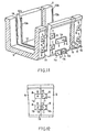
- the abovementioned joint structure comprises an upper connector plate 1 a, a lower connector plate 1b, each connector plate being provided with fastener holes 2 and 3 on each end portion, a stopper 4 formed on each connector plate at the lateral outside of the fastener hole 3, an insert 6 of nut type embedded in a recess 8 formed on the one end of an upright wall of a concrete unit 5, another insert 7 of the same type embedded in another recess 8 formed on the other end of the wall, each recess being adapted to receive the connector plate, a bolt-9 to be screwed into the insert 6 through the hole 2, another bolt 10 to be screwed into the insert 7 through the hole 3, and an eccentric washer plate 11 to be fitted on the bolt 10, the washer plate 11 being contacted at its periphery to the inner side of the stopper 4 after closely contacting the neighboring concrete units to each other.
- the said compressive stress in the lower part is solely borned with the lower portion of the joining end face of the concrete unit 5, because the stopper 4 of the lower connector plate 1b and the eccentric washer plate 11 contacting thereto are disposed so that they never bear the compressive stress in the upper part. Consequently, when the upheaval exceeding the permissible compressive stress of concrete occurs, it causes the buckling and collapse of concrete.
- An object of the present invention is, therefore, to provide a joint structure of eccentric washer plate type which is strong against both upheaval and sinking of channel.
- the joint structure of eccentric washer plate type of the present invention comprises a connector plate formed with two fastener holes and two stoppers, and an eccentric washer plate of which the periphery is contacted with both stoppers, one of the stoppers being disposed between the said fastener holes.
- each concrete unit 5 is U-shaped, and provided with rectangular recess 8 on each outer surface of the front and rear joining ends. Inserts 6 and 7 taking the form of nut are embedded into the central portions of the rear and front recesses 8 and 8, respectively.
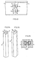
- Each of the upper connector plate 1 a and the lower connector plate 1b is provided with two fastener holes 2 and 3, and the hole 3 is of oblong slot type in order to leave an adjusting margin.
- Each of the connector plates 1 and 1 b has an inner stopper 4a and an outer stopper 4b each taking the form of lengthwise rib.
- each of fasteners 9 and 10 which passes through the said fastener holes 2 and 3 respectively, takes the form of bolt.
- an eccentric washer plate 11 fitted on the bolt 10 at its eccentric axial hole 13 is rotated around the bolt 10 so that the eccentric washer plate 11 comes into contact with both stoppers 4a and 4b at its periphery. After finishing the above operations, the said bolt 10 is completely tightened.
- an operator projection 14 may be formed or mounted on the front face of the washer plate 11 as shown in FIG. 9, or a hole 15 for receiving an operating member such as a pin, a nail and the like may be formed in the eccentric washer plate 11 as shown in FIG. 10.
- each connector plate is provided with two stoppers, namely, the inner stopper 4a disposed between the fastener holes 2 and 3 and the outer stopper 4b disposed at the lateral outside of the fastener hole 3, and the eccentric washer plate 11 fitted on the fastener passing through the fastener hole 3 is adapted to contact with both stoppers 4a and 4b.
- the present invention provides a joint structure having a greater resistance to both sinking and upheaval.
- an insert of bolt type may be embedded in a concrete unit in place of the insert of nut type used in the abovementioned embodiment, with replacing a bolt as fastener by a nut.
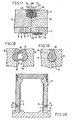
- a concrete unit for channel is never restricted to the unit of U-shaped section, the invention is applicable to other known concrete units of circular pipe form shown in FIG. 21, box or square pipe form shown in FIG. 23, channel form of which the bottom portion is semicircular as shown in FIG. 24, L-shaped form and so on.
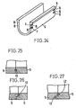
- the invention is applicable not only to an originally integrated or undivided unit but also to a prefabricated unit as shown in FIG. 20.
- the mounting number of connector plate is increased or decreased according to the weight and size of concrete units to be interconnected. Also, the mounting position of connector plate is never limited to the side surface, and then the bottom surface and the top end surface may be used selectively as the mounting place. Where two connector plates 1 a and 1b are used, two stoppers 4a and 4b may be formed or mounted only on one of them as shown in FIGS. 11 and 13.
- FIGS. 14 and 15 exemplify the preferable embodiments of figurate seal member. These seal members are made from chloroprene rubber having good weather-proof and chemicals-proof. The seal member of FIG.
- the seal member 14 comprises a solid body 12a having a hollow 18, and a crescent-shaped sponge portion 12b attached to the one side of the solid body 12a.
- the seal member of FIG. 15 is wholly formed out of sponge rubber.
- the seal member 12 is fitted on the inner edge of the joining end face 19, namely, a receiving groove 17 formed on the edge portion of the water-flowing side, as shown in FIGS. 16 and 18.
- the figurate seal member should have a sectional shape adapted to obtain the sufficient amount of compression corresponding to the volume of joint between the units, so that the water-stopping function can be entirely maintained with filling up the breakage or disjunction of joint owing to the restorative expansion of the compressed portion.
- the mounting position and number of seal members may be changed according to the size of unit and the shape of the joining end as shown in FIGS. 25, 26 and 27.
- the joint structure of eccentric washer plate type of the invention is useful particularly in constructing channels for agriculture, industry and so forth, which have a greater resistance both to sinking and upheaval and are fully protected against leakage of water.
Landscapes
- Engineering & Computer Science (AREA)
- General Engineering & Computer Science (AREA)
- Hydrology & Water Resources (AREA)
- Health & Medical Sciences (AREA)
- Public Health (AREA)
- Water Supply & Treatment (AREA)
- Life Sciences & Earth Sciences (AREA)
- Mechanical Engineering (AREA)
- Civil Engineering (AREA)
- Structural Engineering (AREA)
- Sewage (AREA)
- Joining Of Building Structures In Genera (AREA)
- Connection Of Plates (AREA)
Abstract
Claims (1)
- Structure d'assemblage pour canaux d'amenée d'eau comprenant au moins une plaque de connexion (1a ou 1 b) munie de deux trous de fixation (2, 3) et d'une butée (4b) placée latéralement vers l'extérieur par rapport à l'un des trous de fixation (2, 3), des éléments de fixation (9, 10) traversant lesdits trous de fixation (2, 3) et resserrant la plaque de connexion (1a ou 1b) contre les extrémités à réunir d'éléments de ciment adjacents (5) et une rondelle excentrique (11) située sur l'élément de fixation (10) adjacent à la butée et coopérant avec cette dernière (4b), caractérisée en ce qu'au moins une plaque de connexion (1a ou 1b) est munie d'une autre butée (4a) située entre lesdits trous de fixation (2, 3) et en ce que la rondelle excentrique (11) est placée entre lesdites butées (4a, 4b), la périphérie de la rondelle coopérant avec les deux butées (4a, 4b).
Applications Claiming Priority (2)
| Application Number | Priority Date | Filing Date | Title |
|---|---|---|---|
| JP35303/78 | 1978-03-29 | ||
| JP3530378A JPS54128132A (en) | 1978-03-29 | 1978-03-29 | Joint structure of waterway |
Publications (3)
| Publication Number | Publication Date |
|---|---|
| EP0016837A4 EP0016837A4 (fr) | 1980-09-29 |
| EP0016837A1 EP0016837A1 (fr) | 1980-10-15 |
| EP0016837B1 true EP0016837B1 (fr) | 1982-09-15 |
Family
ID=12438004
Family Applications (1)
| Application Number | Title | Priority Date | Filing Date |
|---|---|---|---|
| EP79900374A Expired EP0016837B1 (fr) | 1978-03-29 | 1979-11-05 | Structure d'assemblage pour canaux d'amenee d'eau |
Country Status (5)
| Country | Link |
|---|---|
| US (1) | US4661008A (fr) |
| EP (1) | EP0016837B1 (fr) |
| JP (1) | JPS54128132A (fr) |
| DE (1) | DE2963660D1 (fr) |
| WO (1) | WO1979000848A1 (fr) |
Families Citing this family (20)
| Publication number | Priority date | Publication date | Assignee | Title |
|---|---|---|---|---|
| JPS6211662U (fr) * | 1985-07-04 | 1987-01-24 | ||
| FR2594458A1 (fr) * | 1986-02-19 | 1987-08-21 | Fremont Claude | Canal d'irrigation en troncons |
| JPS6393170U (fr) * | 1986-12-05 | 1988-06-16 | ||
| US4749307A (en) * | 1987-01-14 | 1988-06-07 | Baltimore Aircoil Company, Inc. | Seal structure for joint between two structural sections |
| CH673805A5 (fr) * | 1987-11-20 | 1990-04-12 | Polatech Gmbh | |
| DE3827041A1 (de) * | 1988-08-10 | 1990-02-15 | Passavant Werke | Entwaesserungsrinne |
| FR2716217B1 (fr) * | 1994-02-16 | 1996-05-03 | Prefaest Sa | Caniveau et élément de caniveau immobilisable. |
| US5522675A (en) * | 1994-12-19 | 1996-06-04 | Abt, Inc. | Method and apparatus for aligning drainage channel sections |
| US5735637A (en) * | 1996-06-03 | 1998-04-07 | Abt, Inc. | Method and apparatus for supporting and anchoring drainage channel sections |
| WO1998011300A1 (fr) * | 1996-09-12 | 1998-03-19 | Jagiecco Jacek | Rigole de deshydratation |
| DE19962989B4 (de) * | 1999-12-24 | 2006-04-13 | Wobben, Aloys, Dipl.-Ing. | Rotorblatt für Windenergieanlagen |
| KR100477558B1 (ko) * | 2001-04-18 | 2005-03-25 | 농업기반공사 | 폴리머 콘크리트 용배수로 |
| US6860678B2 (en) | 2003-01-13 | 2005-03-01 | Abt, Inc. | Method and apparatus for aligning channel sections with an adjustable alignment key |
| WO2016138586A1 (fr) | 2015-03-02 | 2016-09-09 | Valley Blades Limited | Système de niveleuse modulaire pour un versoir |
| FR3033340B1 (fr) * | 2015-03-03 | 2019-04-19 | Aco Severin Ahlmann Gmbh & Co. Kg | Couverture de caniveau et systeme de drainage. |
| JP6612581B2 (ja) * | 2015-10-20 | 2019-11-27 | ケイコン株式会社 | アーチ橋構造用の連接コンクリートブロック体及び上路式アーチ橋 |
| DE102016103275A1 (de) * | 2016-02-24 | 2017-08-24 | ACO Severin Ahlmann GmbH & Co Kommanditgesellschaft | Dichtung einer Entwässerungsrinne |
| CN109281301B (zh) * | 2018-10-22 | 2020-10-30 | 浙江水利水电学院 | 一种吊放灌溉渠施工方法 |
| US11131069B2 (en) | 2019-10-02 | 2021-09-28 | Jay R. Smith Mfg. Co., assumed name of Smith Industries, Inc. | Trench drain alignment system |
| CN113699940B (zh) * | 2021-09-06 | 2022-09-23 | 北京华昊水利水电工程有限责任公司 | 一种渡槽止水结构及其施工方法 |
Family Cites Families (14)
| Publication number | Priority date | Publication date | Assignee | Title |
|---|---|---|---|---|
| DK56325C (da) * | 1936-12-30 | 1939-06-19 | Svensson & Ljungkvist Ab | Anordning ved Trætrapper til Hindring af Knirken af Trinnene |
| US2584709A (en) * | 1949-11-22 | 1952-02-05 | Thompson Prod Inc | Adjustable tie rod |
| US3006443A (en) * | 1954-12-20 | 1961-10-31 | Joseph T Siler | Method and apparatus for attaching juxtaposed members |
| US2863683A (en) * | 1955-12-20 | 1958-12-09 | Rome Cable Corp | Connecting means |
| US2849105A (en) * | 1956-03-21 | 1958-08-26 | Louis L Touton | Conveyer apparatus |
| US3257720A (en) * | 1961-10-27 | 1966-06-28 | Joseph T Siler | Method of joining parts |
| GB987168A (en) * | 1963-12-03 | 1965-03-24 | Conch Int Methane Ltd | A method of mounting metal sheets |
| US3413813A (en) * | 1966-03-09 | 1968-12-03 | Pittsburgh Des Moines Steel | Tunnel support including a yieldable connection |
| FR2159227B1 (fr) * | 1971-11-10 | 1974-05-31 | Guillet Henri | |
| SU585631A1 (ru) * | 1976-02-11 | 1977-12-25 | Особое Конструкторское Бюро Института Космических Исследований Ан Ссср | Устройство дл соединени блоков радиоэлектронной аппаратуры |
| JPS535835A (en) * | 1976-07-05 | 1978-01-19 | Touwa Konkuriito Kk | Method of constructing waterway |
| JPS5373843A (en) * | 1976-11-11 | 1978-06-30 | Touwa Konkuriito Kk | Concrete block for channel construction |
| JPS603187Y2 (ja) * | 1977-02-15 | 1985-01-29 | 徳弘 梅沢 | 水路構築用ブロツクの締結装置 |
| US4145859A (en) * | 1977-07-29 | 1979-03-27 | Armstrong Cork Company | Splice for metal furring strip |
-
1978
- 1978-03-29 JP JP3530378A patent/JPS54128132A/ja active Granted
-
1979
- 1979-03-29 WO PCT/JP1979/000077 patent/WO1979000848A1/fr unknown
- 1979-03-29 DE DE7979900374T patent/DE2963660D1/de not_active Expired
- 1979-11-05 EP EP79900374A patent/EP0016837B1/fr not_active Expired
-
1985
- 1985-10-15 US US06/787,697 patent/US4661008A/en not_active Expired - Fee Related
Also Published As
| Publication number | Publication date |
|---|---|
| JPS571670B2 (fr) | 1982-01-12 |
| DE2963660D1 (en) | 1982-11-04 |
| JPS54128132A (en) | 1979-10-04 |
| US4661008A (en) | 1987-04-28 |
| WO1979000848A1 (fr) | 1979-11-01 |
| EP0016837A4 (fr) | 1980-09-29 |
| EP0016837A1 (fr) | 1980-10-15 |
Similar Documents
| Publication | Publication Date | Title |
|---|---|---|
| EP0016837B1 (fr) | Structure d'assemblage pour canaux d'amenee d'eau | |
| US5309691A (en) | Shear connected structural units | |
| JP2634381B2 (ja) | 分割型ボックスカルバート及びその組立方法 | |
| JPS5948600A (ja) | トンネル覆工構造 | |
| JP4117309B2 (ja) | 可撓継手構造、コンクリートブロック、可撓ジョイント | |
| KR200272596Y1 (ko) | 조립식 암거블럭 | |
| KR20020091617A (ko) | 프리캐스트 구조물 연결부 접합장치 | |
| JPS6219749Y2 (fr) | ||
| JPH0684638B2 (ja) | 組立式地下構築物 | |
| JP2891670B2 (ja) | コンクリート製品の可撓継手構造及びその可撓継手構造を有するコンクリート製品 | |
| JP3026870U (ja) | コンクリート構造物の歪吸収連結構造 | |
| JPH06185035A (ja) | 水路のライニング構造 | |
| JPH0476119A (ja) | 基礎構築用ブロック構造物の接合構造 | |
| JPS6038771Y2 (ja) | コンクリ−トブロツク | |
| JPH0432401Y2 (fr) | ||
| KR200193603Y1 (ko) | 암거설비 | |
| JPH0220287Y2 (fr) | ||
| JPH027999Y2 (fr) | ||
| JPS6322216Y2 (fr) | ||
| JPH0125845B2 (fr) | ||
| KR900008715Y1 (ko) | 콘크리트 농수로 블럭의 연결 접속장치 | |
| JPS6343532B2 (fr) | ||
| JPS5912306Y2 (ja) | 水路の継手構造 | |
| KR19980032236U (ko) | 암거설비 | |
| KR200179201Y1 (ko) | 개거 수로관용 연결장치 |
Legal Events
| Date | Code | Title | Description |
|---|---|---|---|
| PUAI | Public reference made under article 153(3) epc to a published international application that has entered the european phase |
Free format text: ORIGINAL CODE: 0009012 |
|
| 17P | Request for examination filed | ||
| AK | Designated contracting states |
Designated state(s): DE FR GB |
|
| GRAA | (expected) grant |
Free format text: ORIGINAL CODE: 0009210 |
|
| AK | Designated contracting states |
Designated state(s): DE FR GB |
|
| REF | Corresponds to: |
Ref document number: 2963660 Country of ref document: DE Date of ref document: 19821104 |
|
| PGFP | Annual fee paid to national office [announced via postgrant information from national office to epo] |
Ref country code: FR Payment date: 19900216 Year of fee payment: 12 |
|
| PGFP | Annual fee paid to national office [announced via postgrant information from national office to epo] |
Ref country code: GB Payment date: 19900331 Year of fee payment: 12 |
|
| PG25 | Lapsed in a contracting state [announced via postgrant information from national office to epo] |
Ref country code: GB Effective date: 19910329 |
|
| PGFP | Annual fee paid to national office [announced via postgrant information from national office to epo] |
Ref country code: DE Payment date: 19910529 Year of fee payment: 13 |
|
| GBPC | Gb: european patent ceased through non-payment of renewal fee | ||
| PG25 | Lapsed in a contracting state [announced via postgrant information from national office to epo] |
Ref country code: FR Effective date: 19911129 |
|
| REG | Reference to a national code |
Ref country code: FR Ref legal event code: ST |
|
| PG25 | Lapsed in a contracting state [announced via postgrant information from national office to epo] |
Ref country code: DE Effective date: 19921201 |
|
| PLBE | No opposition filed within time limit |
Free format text: ORIGINAL CODE: 0009261 |
|
| STAA | Information on the status of an ep patent application or granted ep patent |
Free format text: STATUS: NO OPPOSITION FILED WITHIN TIME LIMIT |