EP0016686B1 - Pneumatique pour véhicule - Google Patents
Pneumatique pour véhicule Download PDFInfo
- Publication number
- EP0016686B1 EP0016686B1 EP19800400319 EP80400319A EP0016686B1 EP 0016686 B1 EP0016686 B1 EP 0016686B1 EP 19800400319 EP19800400319 EP 19800400319 EP 80400319 A EP80400319 A EP 80400319A EP 0016686 B1 EP0016686 B1 EP 0016686B1
- Authority
- EP
- European Patent Office
- Prior art keywords
- ply
- folded
- belt
- edges
- width
- Prior art date
- Legal status (The legal status is an assumption and is not a legal conclusion. Google has not performed a legal analysis and makes no representation as to the accuracy of the status listed.)
- Expired
Links
- 238000005096 rolling process Methods 0.000 claims description 7
- 239000004753 textile Substances 0.000 claims description 3
- 230000007423 decrease Effects 0.000 claims description 2
- 239000002184 metal Substances 0.000 claims description 2
- 230000002238 attenuated effect Effects 0.000 claims 2
- 239000010410 layer Substances 0.000 description 21
- 238000010276 construction Methods 0.000 description 9
- 239000000203 mixture Substances 0.000 description 4
- 229920003235 aromatic polyamide Polymers 0.000 description 3
- 239000004677 Nylon Substances 0.000 description 2
- 229920000297 Rayon Polymers 0.000 description 2
- 239000004760 aramid Substances 0.000 description 2
- 230000000052 comparative effect Effects 0.000 description 2
- 238000010586 diagram Methods 0.000 description 2
- 239000004744 fabric Substances 0.000 description 2
- 230000002349 favourable effect Effects 0.000 description 2
- 229920001778 nylon Polymers 0.000 description 2
- 229920000728 polyester Polymers 0.000 description 2
- 239000002964 rayon Substances 0.000 description 2
- 230000035945 sensitivity Effects 0.000 description 2
- FGRBYDKOBBBPOI-UHFFFAOYSA-N 10,10-dioxo-2-[4-(N-phenylanilino)phenyl]thioxanthen-9-one Chemical compound O=C1c2ccccc2S(=O)(=O)c2ccc(cc12)-c1ccc(cc1)N(c1ccccc1)c1ccccc1 FGRBYDKOBBBPOI-UHFFFAOYSA-N 0.000 description 1
- 239000011324 bead Substances 0.000 description 1
- 238000005452 bending Methods 0.000 description 1
- 230000003247 decreasing effect Effects 0.000 description 1
- 230000000593 degrading effect Effects 0.000 description 1
- 230000005489 elastic deformation Effects 0.000 description 1
- 239000011152 fibreglass Substances 0.000 description 1
- 239000011521 glass Substances 0.000 description 1
- 239000011229 interlayer Substances 0.000 description 1
- XLYOFNOQVPJJNP-UHFFFAOYSA-N water Substances O XLYOFNOQVPJJNP-UHFFFAOYSA-N 0.000 description 1
Images
Classifications
-
- B—PERFORMING OPERATIONS; TRANSPORTING
- B60—VEHICLES IN GENERAL
- B60C—VEHICLE TYRES; TYRE INFLATION; TYRE CHANGING; CONNECTING VALVES TO INFLATABLE ELASTIC BODIES IN GENERAL; DEVICES OR ARRANGEMENTS RELATED TO TYRES
- B60C9/00—Reinforcements or ply arrangement of pneumatic tyres
- B60C9/18—Structure or arrangement of belts or breakers, crown-reinforcing or cushioning layers
- B60C9/20—Structure or arrangement of belts or breakers, crown-reinforcing or cushioning layers built-up from rubberised plies each having all cords arranged substantially parallel
-
- B—PERFORMING OPERATIONS; TRANSPORTING
- B60—VEHICLES IN GENERAL
- B60C—VEHICLE TYRES; TYRE INFLATION; TYRE CHANGING; CONNECTING VALVES TO INFLATABLE ELASTIC BODIES IN GENERAL; DEVICES OR ARRANGEMENTS RELATED TO TYRES
- B60C9/00—Reinforcements or ply arrangement of pneumatic tyres
- B60C9/18—Structure or arrangement of belts or breakers, crown-reinforcing or cushioning layers
- B60C9/26—Folded plies
Definitions
- the invention relates to improvements to tires with a radial carcass and a crown belt specially intended for equipping vehicles capable of traveling at high speeds and such as passenger cars, sports and competition cars, airplanes.
- a type of crown belt which is particularly suitable for these tires comprises at least two plies of cords oriented at small angles of the order of 20 ° relative to the equatorial plane, including an unfolded ply of width approximately equal to the width of the rolling surface and a wider ply, the lateral edges of which are folded axially inwards and applied against one face of the other ply.
- This type of belt is illustrated for example in FR patents. A 1.228.241, FR. A 2.235.810 and FR. A 2,389.502. Applied to the tires of fast vehicles considered here, this type of belt has good resistance to the forces developed during rolling at high speed, in particular in the lateral zones close to the edges of the belt, and it gives the tire excellent road qualities.
- the object of the invention is to improve these tires so as to avoid the above-mentioned drawbacks without compromising the other road qualities obtained thanks to this type of crown belt.
- the invention therefore relates to a tire with a low cross section less than 0.8 of the type with a radial carcass and a crown belt comprising at least two plies of cables oriented at small angles of the order of 20 ° relative to the equatorial plane, of which an unfolded ply of width approximately equal to the width of the rolling surface and a wider ply whose lateral edges are folded, axially inwards and applied against a " ⁇ face of the other ply, characterized in that the two plies of the belt are spaced radially by a layer of rubber confined between the two plies, extending transversely as far as the folds of the ply with folded edges and whose thickness decreases towards the edges of the belt, this layer of rubber having a section of lenticular shape such that the upper ply of the belt has a
- a belt of the type comprising an unfolded ply and a wider ply with folded edges can be completed with one or more intermediate plies not folded in ropes oriented obliquely, helping to increase the overall resistance of the belt, by especially for large tires.
- these intermediate plies in oblique cords do not substantially modify the transverse curvature of the belt, so that they cannot be assimilated to the layer of lenticular gum confined between the belt plies as defined above.
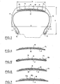
- the tire illustrated in FIG. 1 comprises a carcass 10 consisting of one or more plies of “cord fabric” made of flexible cords such as rayon cords, aromatic polyamide nylon, polyester, fiberglass or metal, these cords being oriented according to radial or almost radial planes.
- the edges 11 of the carcass plies are folded around the rods 12 of the beads.
- the carcass is covered on the sides by the rubber side strips 13 and it carries at its top a belt 14 which is inextensible in the circumferential direction.
- the belt is covered by the rubber tread 15 having the tread suitable for the use of the tire and as a whole it has a width L approximately equal to or slightly greater than the width of the tread surface 15.
- the tire When the tire is mounted on a normal rim and inflated to its working pressure, it has a low profile section shape in which the ratio of the height H to the width G of the section is equal to or less than 0.8 with a relatively wide and flat rolling surface or slightly curved in the transverse direction, its transverse radius of curvature being in any case greater than the radius of the longitudinal curvature corresponding to the diameter of the tire.
- the crown belt 14 consists of at least two plies of cord fabric 16-17 in parallel flexible cords oriented in opposite directions at small angles, of the order of about 20 ° relative to the equatorial plane of the tire.
- the ply 16 is an unfolded annular ply having a width slightly less than the width L of the belt while the ply 17 has a significantly larger developed width and its side edges 17.1 are folded around the edges of the ply 16 and folded down. against the upper face of the latter.
- the developed width of the ply 17 is not more than 1.5 times the width of the belt so that the ends of the folded edges 17.1 are spaced transversely from each other by a distance at least equal to half the width L of the belt.
- the width of the folded edges 17.1 is therefore of the order of approximately 15 to 70 millimeters in order to properly cover the edges of the ply 16 and to reinforce and stiffen the lateral zones of the belt.
- a layer of rubber 18 which has a maximum thickness in the central zone of the belt and which tapers towards the edges. Its width is approximately equal to that of the unfolded ply 16 so that the thinned edges of this layer of gum extend to the bottom of the folds of the ply 17.
- the thickness of this layer of gum 18 is, in the central part of the tire, of the order of 2.5 to 6 mm approximately so that it gives the upper ply 16 of the belt an accentuated transverse convexity having an average radius of curvature less than the radius of transverse curvature of the tablecloth 17,
- the ply 17 adjacent to the carcass 10 therefore has a less pronounced transverse curvature whose radius is equal to or greater than the radius of its longitudinal curvature, with a layout substantially parattete to that of the rolling surface.
- the belt Due to the radial spacing of the two plies 16-17 by the interposed rubber layer 18, the belt has resistance to bending inward. which is higher than that of a belt of the same type which does not have this layer of gum and this all the more so since the layer of gum 18 is confined between the two plies 16-17 whose lateral parts are secured by the folding the edges 17.1.
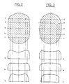
- FIGS. 2 and 3 show diagrams drawn up from readings of the contact pressures at different points on the transverse lines a, b, c of the footprints of a control tire and of a tire according to the invention having belts of the same type, one without and the other with the layer of lenticular rubber 18 according to FIG. 1. It can be seen that the curves in FIG. 3 are much flatter and that they have less tendency to bend at the center with respect to those of the control tire in figure 2.
- the same tires subjected to the other usual comparative tests of high speed, endurance, road holding, braking and comfort show that the tires having the belt construction according to FIG. 1 have properties as good or a little better than those of tires witnesses.
- the lenticular shape of the interlayer profile 18 has, compared to other solutions, at least the following two advantages: on the one hand it very little increases the transverse rigidity of the belt in its plane, which makes it possible not to reduce the road holding qualities inherent in this type of folded belt. On the other hand, it does not significantly increase the thicknesses on the sides of the belt, which would have the consequence of degrading the qualities of resistance at high speed and the endurance qualities of tires having this type of belt.
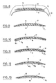
- Variants in the construction of the belt of FIG. 1 can be produced with the aim of adjusting or improving certain characteristics of the behavior of the tires according to the uses for which they are intended.
- FIG. 4 shows a construction of a belt with folded edges of the same kind but in which the intermediate layer of rubber 18 is wider than the non-folded ply 16 so as to overflow on each side.
- the lateral folds of the ply 17 are thus somewhat distant from the lateral edges of the ply 16 so as to increase the rigidity of the edges of the belt, in order to achieve a belt that is generally wider than the rolling surface to improve the property. handling of the tire, either in order to improve the resistance to detachment of the edges of the belt at high speed.
- the intermediate rubber layer 18 has a developed width greater than the width of the unfolded ply 16 and its edges 18.1 are folded around the edges of said ply 16 so as to space them from the bottom of the folds of the ply 17.
- the layer of rubber 18 more advantageously has a developed width comprised between the width of the sheet 16 and the width of the sheet 17 so that the folded portions 18.1 of the layer of rubber are completely wrapped and covered by the folded edges 17.1 of the ply 17.
- FIGS. 6 and 7 illustrate exemplary embodiments of a belt comprising more than two plies of cables and a layer of rubber sandwiched between two of these layers.
- the first two plies are respectively a broad ply, folded edges 17 and an unfolded ply 16 appliqL: 9 one against the other.
- a third ply 19 is placed above the rubber layer 18 and its edges are covered by the folded edges 17.1 of the first ply.
- the cables of the two adjacent plies 16-17 are oriented in opposite directions at small angles of the order of 20 ° while the cables of the upper ply 19 can be oriented at a greater angle of the order from 60 to 90 °.
- FIG. 6 illustrates exemplary embodiments of a belt comprising more than two plies of cables and a layer of rubber sandwiched between two of these layers.
- the first two plies are respectively a broad ply, folded edges 17 and an unfolded ply 16 appliqL: 9 one against the other.
- a third ply 19
- the rubber layer 18 is inserted between the first ply with folded edges 17 and a set of two superimposed plies 16a and 16b which may have decreasing widths and whose edges are covered by the folded edges of the ply 17. All these sheets or at least two of them have their cords oriented in opposite directions at small angles of the order of 20 °.
- Figure 8 shows yet another embodiment in which only the edges of the rubber layer 18 are inserted into the folds of the ply 17 while the upper ply 16 at its edges superimposed on the folded edges 17.1 of this ply.
- FIG. 9 to 13 schematically illustrate several embodiments of this kind which correspond i vely to the embodiments of Figures 1, 5, 6, 7 and 8 but inverted, with the edges 17.1 of the wide ply folded over the inner face of the belt.
- rubber mixtures of common type can be used. Because this layer of rubber is confined inside the belt and by the folded edges 17.1, its own rigidity does not seem to be essential, although the hardness of the mixture can be chosen to adjust certain properties of the tires to the intended uses. It is however more advantageous to choose mix compositions with low hysteresis, which give off little heat in service of the tire.
- the usual textile cords such as rayon cords, nylon, polyester, aramids, glass cords or metallic cords can be used. All the plies can be made with the same cords or some can be made of cords different from those of the other plies.
- a particularly advantageous combination consists in using for all the plies high modulus and high tenacity cords to give the belt a high resistance to extension in the circumferential direction and a high stiffness in its plane, which is favorable good road holding and low drift.
- metallic cords will preferably be used for the unfolded tablecloths and aramid textile cords for the tablecloths with folded edges.
Landscapes
- Engineering & Computer Science (AREA)
- Mechanical Engineering (AREA)
- Tires In General (AREA)
- Ropes Or Cables (AREA)
Applications Claiming Priority (2)
| Application Number | Priority Date | Filing Date | Title |
|---|---|---|---|
| FR7906680 | 1979-03-14 | ||
| FR7906680A FR2451277A1 (fr) | 1979-03-14 | 1979-03-14 | Pneumatique a ceinture, notamment pour vehicule rapide |
Publications (2)
| Publication Number | Publication Date |
|---|---|
| EP0016686A1 EP0016686A1 (fr) | 1980-10-01 |
| EP0016686B1 true EP0016686B1 (fr) | 1982-11-24 |
Family
ID=9223181
Family Applications (1)
| Application Number | Title | Priority Date | Filing Date |
|---|---|---|---|
| EP19800400319 Expired EP0016686B1 (fr) | 1979-03-14 | 1980-03-11 | Pneumatique pour véhicule |
Country Status (3)
| Country | Link |
|---|---|
| EP (1) | EP0016686B1 (OSRAM) |
| DE (1) | DE3061126D1 (OSRAM) |
| FR (1) | FR2451277A1 (OSRAM) |
Families Citing this family (4)
| Publication number | Priority date | Publication date | Assignee | Title |
|---|---|---|---|---|
| DE3869997D1 (de) * | 1987-02-19 | 1992-05-21 | Sumitomo Rubber Ind | Fahrzeugreifen. |
| US5042546A (en) * | 1987-11-16 | 1991-08-27 | The Goodyear Tire & Rubber Company | Radial ply pneumatic tire with reverse curvature carcass ply |
| TR25524A (tr) * | 1987-11-16 | 1993-03-18 | Goodyear Tire & Rubber | Tersine kivrik karkas kati olan radyal-kati pnömatik dis lastik. |
| US6439288B1 (en) | 2000-11-28 | 2002-08-27 | Bridgestone/Firestone North American Tire, Llc | Pneumatic tire with variable thickness band element |
Family Cites Families (7)
| Publication number | Priority date | Publication date | Assignee | Title |
|---|---|---|---|---|
| IT514343A (OSRAM) * | ||||
| FR1290231A (fr) * | 1961-02-24 | 1962-04-13 | Kleber Colombes | Enveloppe de pneumatique |
| BE639433A (OSRAM) * | 1962-10-31 | |||
| US3931844A (en) * | 1973-05-14 | 1976-01-13 | Uniroyal, S.A. | Cushioned tread tire |
| DE2355338A1 (de) * | 1973-11-06 | 1975-05-15 | Uniroyal Ag | Verstaerkungseinlage in form eines guertels fuer fahrzeugluftreifen |
| DE2518223C2 (de) * | 1975-04-24 | 1985-04-25 | Continental Gummi-Werke Ag, 3000 Hannover | Fahrzeugluftreifen |
| DE2719798A1 (de) * | 1977-05-03 | 1978-11-16 | Uniroyal Ag | Hochbelastbarer stahlkord-guertelreifen, insbesondere fuer lastkraftwagen, schwer- und/oder grossfahrzeuge mit einer mindestens einlagigen radialkarkasse, vorzugsweise aus stahlkord, und einer mehrlagigen guertelartigen verstaerkung, welche wenigstens eine faltlage aus stahlkord und wenigstens eine weitere ungefaltete lage aus textilkord aufweist |
-
1979
- 1979-03-14 FR FR7906680A patent/FR2451277A1/fr active Granted
-
1980
- 1980-03-11 DE DE8080400319T patent/DE3061126D1/de not_active Expired
- 1980-03-11 EP EP19800400319 patent/EP0016686B1/fr not_active Expired
Also Published As
| Publication number | Publication date |
|---|---|
| FR2451277A1 (fr) | 1980-10-10 |
| DE3061126D1 (en) | 1982-12-30 |
| FR2451277B1 (OSRAM) | 1982-10-01 |
| EP0016686A1 (fr) | 1980-10-01 |
Similar Documents
| Publication | Publication Date | Title |
|---|---|---|
| JP4328371B2 (ja) | 自動二輪車用空気入りタイヤ | |
| EP1062106B1 (fr) | Pneumatique a armature de sommet triangulee | |
| JP4040893B2 (ja) | スクーター用空気入りラジアルタイヤおよびスクーター | |
| LU84085A1 (fr) | Pneumatique pour vehicules automobiles a basse absorption de puissance | |
| WO2014207094A1 (fr) | Pneumatique a carcasse radiale ou croisee | |
| WO2022270094A1 (ja) | タイヤ | |
| JP3648009B2 (ja) | 空気入りタイヤの装着方法 | |
| WO2003095242A1 (fr) | Pneumatique pour deux roues | |
| US8127813B2 (en) | Pneumatic tire for two-wheeled vehicle | |
| EP1397263A1 (fr) | Pneumatique a bourrelet renforce | |
| WO2011107541A1 (fr) | Pneumatique pour vehicules comportant une bande de roulement constituee de plusieurs melanges et une armature de carcasse radiale formee d'au moins deux couches | |
| JP5322697B2 (ja) | 自動二輪車用空気入りタイヤ | |
| CN101678721A (zh) | 机动两轮车用充气轮胎 | |
| EP0016686B1 (fr) | Pneumatique pour véhicule | |
| JPH03139402A (ja) | 空気入りタイヤ | |
| FR3020013A1 (fr) | Adaptateur pour ensemble roulant et ensemble roulant le comprenant | |
| EP1179441B1 (fr) | Pneumatique a armature dissymétrique de sommet et méthode de montage sur un véhicule | |
| FR2624442A1 (fr) | Pneumatique a flancs composites | |
| FR2566335A1 (fr) | Pneumatique radial pour fortes charges | |
| JPH06297913A (ja) | ラジアルタイヤ | |
| FR2550135A1 (fr) | Structure de pneumatique radial pour motocyclette | |
| EP1011992B1 (fr) | Armature de sommet pour pneumatique | |
| WO2011107543A1 (fr) | Pneumatique pour vehicules comportant une bande de roulement constituee de plusieurs melanges et une armature de carcasse formee d'au moins deux couches. | |
| US4966215A (en) | Tire pair for a two-wheeled vehicle | |
| CH624889A5 (OSRAM) |
Legal Events
| Date | Code | Title | Description |
|---|---|---|---|
| PUAI | Public reference made under article 153(3) epc to a published international application that has entered the european phase |
Free format text: ORIGINAL CODE: 0009012 |
|
| AK | Designated contracting states |
Designated state(s): BE CH DE GB IT LU NL SE |
|
| 17P | Request for examination filed |
Effective date: 19810120 |
|
| ITCL | It: translation for ep claims filed |
Representative=s name: JACOBACCI CASETTA & PERANI S.P.A. |
|
| DET | De: translation of patent claims | ||
| ITF | It: translation for a ep patent filed | ||
| GRAA | (expected) grant |
Free format text: ORIGINAL CODE: 0009210 |
|
| AK | Designated contracting states |
Designated state(s): BE CH DE GB IT LU NL SE |
|
| REF | Corresponds to: |
Ref document number: 3061126 Country of ref document: DE Date of ref document: 19821230 |
|
| PGFP | Annual fee paid to national office [announced via postgrant information from national office to epo] |
Ref country code: LU Payment date: 19830302 Year of fee payment: 4 |
|
| PGFP | Annual fee paid to national office [announced via postgrant information from national office to epo] |
Ref country code: CH Payment date: 19830323 Year of fee payment: 4 |
|
| PG25 | Lapsed in a contracting state [announced via postgrant information from national office to epo] |
Ref country code: LU Free format text: LAPSE BECAUSE OF NON-PAYMENT OF DUE FEES Effective date: 19830331 |
|
| PGFP | Annual fee paid to national office [announced via postgrant information from national office to epo] |
Ref country code: SE Payment date: 19830331 Year of fee payment: 4 Ref country code: NL Payment date: 19830331 Year of fee payment: 4 |
|
| PG25 | Lapsed in a contracting state [announced via postgrant information from national office to epo] |
Ref country code: SE Effective date: 19840312 |
|
| PG25 | Lapsed in a contracting state [announced via postgrant information from national office to epo] |
Ref country code: CH Effective date: 19840331 |
|
| PGFP | Annual fee paid to national office [announced via postgrant information from national office to epo] |
Ref country code: BE Payment date: 19840331 Year of fee payment: 5 |
|
| PG25 | Lapsed in a contracting state [announced via postgrant information from national office to epo] |
Ref country code: NL Effective date: 19841001 |
|
| NLV4 | Nl: lapsed or anulled due to non-payment of the annual fee | ||
| REG | Reference to a national code |
Ref country code: CH Ref legal event code: PL |
|
| PG25 | Lapsed in a contracting state [announced via postgrant information from national office to epo] |
Ref country code: BE Effective date: 19860331 |
|
| BERE | Be: lapsed |
Owner name: PNEUMATIQUES CAOUTCHOUC MANUFACTURE ET PLASTIQUES Effective date: 19860331 |
|
| EUG | Se: european patent has lapsed |
Ref document number: 80400319.2 Effective date: 19850529 |
|
| PGFP | Annual fee paid to national office [announced via postgrant information from national office to epo] |
Ref country code: GB Payment date: 19960311 Year of fee payment: 17 |
|
| PG25 | Lapsed in a contracting state [announced via postgrant information from national office to epo] |
Ref country code: GB Effective date: 19970311 |
|
| PGFP | Annual fee paid to national office [announced via postgrant information from national office to epo] |
Ref country code: DE Payment date: 19970530 Year of fee payment: 18 |
|
| GBPC | Gb: european patent ceased through non-payment of renewal fee |
Effective date: 19970311 |
|
| PG25 | Lapsed in a contracting state [announced via postgrant information from national office to epo] |
Ref country code: DE Free format text: LAPSE BECAUSE OF NON-PAYMENT OF DUE FEES Effective date: 19981201 |
|
| PLBE | No opposition filed within time limit |
Free format text: ORIGINAL CODE: 0009261 |
|
| STAA | Information on the status of an ep patent application or granted ep patent |
Free format text: STATUS: NO OPPOSITION FILED WITHIN TIME LIMIT |