EP0016639B1 - Verfahren und Vorrichtung zur Bestimmung der Abriebeigenschaften von Fluiden, dieses Verfahren verwendende Methode zur Kontrolle der Abnutzung von Lagern und mit dieser Vorrichtung ausgestattete Maschine - Google Patents
Verfahren und Vorrichtung zur Bestimmung der Abriebeigenschaften von Fluiden, dieses Verfahren verwendende Methode zur Kontrolle der Abnutzung von Lagern und mit dieser Vorrichtung ausgestattete Maschine Download PDFInfo
- Publication number
- EP0016639B1 EP0016639B1 EP80300846A EP80300846A EP0016639B1 EP 0016639 B1 EP0016639 B1 EP 0016639B1 EP 80300846 A EP80300846 A EP 80300846A EP 80300846 A EP80300846 A EP 80300846A EP 0016639 B1 EP0016639 B1 EP 0016639B1
- Authority
- EP
- European Patent Office
- Prior art keywords
- film
- fluid
- abrasiveness
- resistance
- head
- Prior art date
- Legal status (The legal status is an assumption and is not a legal conclusion. Google has not performed a legal analysis and makes no representation as to the accuracy of the status listed.)
- Expired
Links
- 239000012530 fluid Substances 0.000 title claims abstract description 44
- 238000000034 method Methods 0.000 title claims abstract description 31
- 238000012544 monitoring process Methods 0.000 title claims description 4
- 239000010408 film Substances 0.000 claims abstract description 80
- 238000012360 testing method Methods 0.000 claims abstract description 19
- 239000002245 particle Substances 0.000 claims abstract description 17
- 239000004020 conductor Substances 0.000 claims abstract description 12
- 229910052751 metal Inorganic materials 0.000 claims abstract description 8
- 239000002184 metal Substances 0.000 claims abstract description 8
- 239000010409 thin film Substances 0.000 claims abstract description 6
- 239000012777 electrically insulating material Substances 0.000 claims description 7
- 230000008021 deposition Effects 0.000 claims description 5
- 239000011236 particulate material Substances 0.000 claims description 5
- 239000002002 slurry Substances 0.000 claims description 4
- 230000001419 dependent effect Effects 0.000 claims 1
- 238000005299 abrasion Methods 0.000 abstract description 14
- 239000007789 gas Substances 0.000 abstract description 5
- 239000007788 liquid Substances 0.000 abstract description 3
- 239000002923 metal particle Substances 0.000 abstract description 3
- 239000003921 oil Substances 0.000 description 18
- 238000005259 measurement Methods 0.000 description 7
- 229910001120 nichrome Inorganic materials 0.000 description 7
- PNEYBMLMFCGWSK-UHFFFAOYSA-N aluminium oxide Inorganic materials [O-2].[O-2].[O-2].[Al+3].[Al+3] PNEYBMLMFCGWSK-UHFFFAOYSA-N 0.000 description 6
- 238000000151 deposition Methods 0.000 description 6
- 230000003628 erosive effect Effects 0.000 description 5
- 239000000463 material Substances 0.000 description 5
- PCHJSUWPFVWCPO-UHFFFAOYSA-N gold Chemical compound [Au] PCHJSUWPFVWCPO-UHFFFAOYSA-N 0.000 description 4
- 239000010931 gold Substances 0.000 description 4
- 229910052737 gold Inorganic materials 0.000 description 4
- 239000000203 mixture Substances 0.000 description 4
- 239000010453 quartz Substances 0.000 description 4
- VYPSYNLAJGMNEJ-UHFFFAOYSA-N silicon dioxide Inorganic materials O=[Si]=O VYPSYNLAJGMNEJ-UHFFFAOYSA-N 0.000 description 4
- VYZAMTAEIAYCRO-UHFFFAOYSA-N Chromium Chemical compound [Cr] VYZAMTAEIAYCRO-UHFFFAOYSA-N 0.000 description 3
- 229910052804 chromium Inorganic materials 0.000 description 3
- 239000011651 chromium Substances 0.000 description 3
- 230000000694 effects Effects 0.000 description 3
- 239000013528 metallic particle Substances 0.000 description 3
- 230000035945 sensitivity Effects 0.000 description 3
- 239000000758 substrate Substances 0.000 description 3
- 239000000725 suspension Substances 0.000 description 3
- 238000007738 vacuum evaporation Methods 0.000 description 3
- 238000002061 vacuum sublimation Methods 0.000 description 3
- XEEYBQQBJWHFJM-UHFFFAOYSA-N Iron Chemical compound [Fe] XEEYBQQBJWHFJM-UHFFFAOYSA-N 0.000 description 2
- PXHVJJICTQNCMI-UHFFFAOYSA-N Nickel Chemical compound [Ni] PXHVJJICTQNCMI-UHFFFAOYSA-N 0.000 description 2
- 230000015556 catabolic process Effects 0.000 description 2
- 230000000052 comparative effect Effects 0.000 description 2
- 238000010586 diagram Methods 0.000 description 2
- 238000011835 investigation Methods 0.000 description 2
- 239000007787 solid Substances 0.000 description 2
- 238000004544 sputter deposition Methods 0.000 description 2
- -1 10-5 torr) Chemical compound 0.000 description 1
- 229920005439 Perspex® Polymers 0.000 description 1
- BQCADISMDOOEFD-UHFFFAOYSA-N Silver Chemical compound [Ag] BQCADISMDOOEFD-UHFFFAOYSA-N 0.000 description 1
- 229910000831 Steel Inorganic materials 0.000 description 1
- 229910045601 alloy Inorganic materials 0.000 description 1
- 239000000956 alloy Substances 0.000 description 1
- QVGXLLKOCUKJST-UHFFFAOYSA-N atomic oxygen Chemical compound [O] QVGXLLKOCUKJST-UHFFFAOYSA-N 0.000 description 1
- 239000012671 ceramic insulating material Substances 0.000 description 1
- 230000003749 cleanliness Effects 0.000 description 1
- 239000002817 coal dust Substances 0.000 description 1
- 238000005516 engineering process Methods 0.000 description 1
- 238000002474 experimental method Methods 0.000 description 1
- 239000011521 glass Substances 0.000 description 1
- 229910052742 iron Inorganic materials 0.000 description 1
- 239000004922 lacquer Substances 0.000 description 1
- 238000012423 maintenance Methods 0.000 description 1
- 238000004519 manufacturing process Methods 0.000 description 1
- 229910001092 metal group alloy Inorganic materials 0.000 description 1
- 229910052759 nickel Inorganic materials 0.000 description 1
- 229910000623 nickel–chromium alloy Inorganic materials 0.000 description 1
- 239000001301 oxygen Substances 0.000 description 1
- 229910052760 oxygen Inorganic materials 0.000 description 1
- 239000013618 particulate matter Substances 0.000 description 1
- 239000003208 petroleum Substances 0.000 description 1
- 239000004926 polymethyl methacrylate Substances 0.000 description 1
- 238000012552 review Methods 0.000 description 1
- 229910052594 sapphire Inorganic materials 0.000 description 1
- 239000010980 sapphire Substances 0.000 description 1
- 239000010959 steel Substances 0.000 description 1
- 238000000859 sublimation Methods 0.000 description 1
- 230000008022 sublimation Effects 0.000 description 1
- 238000007740 vapor deposition Methods 0.000 description 1
- 230000004580 weight loss Effects 0.000 description 1
Images
Classifications
-
- G—PHYSICS
- G01—MEASURING; TESTING
- G01N—INVESTIGATING OR ANALYSING MATERIALS BY DETERMINING THEIR CHEMICAL OR PHYSICAL PROPERTIES
- G01N3/00—Investigating strength properties of solid materials by application of mechanical stress
- G01N3/56—Investigating resistance to wear or abrasion
- G01N3/567—Investigating resistance to wear or abrasion by submitting the specimen to the action of a fluid or of a fluidised material, e.g. cavitation, jet abrasion
Definitions
- the present invention relates to a method and apparatus for the determination of the degree of abrasiveness of fluid compositions, for example liquids or gases containing particulate matter, such as oils containing metallic particles, and slurries.
- fluid compositions for example liquids or gases containing particulate matter, such as oils containing metallic particles, and slurries.
- British Patent Specification No. ⁇ BA ⁇ 1341814 discloses a device for use in the continuous monitoring of wear at a surface of a machine element, the device including a resistive body and two electrodes attached thereto, the device being situated within the said element, exposed at the wear surface to wear with the element and hence being reduced in current carrying cross-sectional area.
- the wearing of the body is caused by a part of the machine with which the body is in contact, and not by a fluid.
- the body is embedded in the element and must be at least as soft as the machine element, so that it does not wear more slowly than the machine element.
- resistive body used in this prior proposal is eroded only at its edge so that the sensitivity of the device is slow, significant changes to resistance being achieved only when a large degree of wear to the machine element has taken place.
- Page 892 discloses a technique which shows the quantitative comparison of the erosion severity of container walls resulting from the impact of solid particles carried by the fluid within the container.
- the technique is based upon the measurement of electrical resistance of a thick film 40 u of colloidal silver in lacquer sprayed onto the surface of the non-conducting wall under investigation. Erosion of the film caused by the impact of solid particles causes an increase in its electrical resistance.
- the time rate of change of conductance, 1/R is proportional to the rate of change of film thickness. This leads to an experimental quantity which is proportional to the volume erosion rate. Calibration experiments show peak erosion rates at particle incidence angles of about 45°.
- British Patent No. GB-A-1320122 discloses a test head comprising a non conducting re-cyrstallized alumina substrate in the shape of a magnetic recording head onto which several parallel Nichrome strips are deposited by vacuum sublimation at a temperature of 300°C to a thickness of 70-100 nm (70 to 1,000 A).
- the substrate is heated to a temperature of 900°C in air for one hour.
- a further 100 nm (1,000 A) thick layer of Nichrome is then deposited as before on top of each existing strip.
- the substrate is then heated to 300°C in air before gold contact areas are deposited by vacuum evaporation over the ends of the Nichrome strips, to facilitate the electrical connection of ancillary equipment.
- test head The purpose of this test head is to provide a quick and simple method for determining the abrasiveness of magnetic recording tape.
- the record head on a tape machine is substituted by the test head, and when a tape is passed over the test head the rate of change of electrical resistance of the Nichrome elements is related to the abrasiveness of the tape.
- French Patent No. FR-A-1 557001 relates to a method and apparatus for determining the abrasiveness of a suspension of quartz particles.
- the apparatus essentially consists of a pressurized reservoir containing the quartz suspension, a test chamber fitted with a nozzle and test specimen, and some associated pipework and valves.
- the fluid containing the quartz particles is delivered under pressure to the nozzle and the resulting jet is directed at the metal test specimen which is in the form of a metal plate.
- the erosion rate of the metal plate over a given time interval is calculated by measuring its change in weight over that interval. This weight loss is related to the abrasivity of the quartz suspension.
- the present invention provides a method for determining the degree of abrasiveness of a fluid containing particulate material, which comprises abrading with the said fluid a film (27) of an electrically conducting material on the surface of an electrically insulating material (29) and observing the change in electrical resistance of the electrically conducting film (27) characterised in that the film is abraded by directing at it a jet of the said fluid, and in that the film has a very low or negative temperature coefficient of resistance and a thickness of less than 300 n.m. (3000 A).
- the invention also provides a method of measuring the particle content of a fluid which method comprises determining the abrasiveness of the fluid by the method of the previous paragraph and from the result obtained calculating the particle content.
- the electrically insulating material bearing the conducting film is generally referred to as a testing head, and the testing head may conveniently be formed by depositing the film by means of vacuum evaporation, vacuum sublimation or sputtering.
- the invention includes apparatus for determining the abrasiveness of a fluid containing particulate material, which apparatus comprises a testing head having a film (27) of .an electrically conducting material deposited on an electrically insulating material (29) and means (31) for making electrical contact with the film to sense its electrical resistance, and means for bringing the said fluid into contact with the head to abrade the film, characterised in that the means for bringing the fluid into contact with the head includes a nozzle (33) for directing a jet of the fluid onto the head, and in that the film of electrically conducting material has a very low or negative temperature coefficient of resistance and a thickness of less than 300 n.m. (3000 A).
- the invention also provides a machine provided with apparatus as defined in the previous paragraph for measuring the abrasiveness of oil used in the machine.
- the quantity which is directly measured by the method of the invention is the change in electrical resistance of the conducting film, and hence the degree to which the fluid causes the abrasion of the film, this quantity will be an indirect indication in certain circumstances of other parameters of the fluid, such as the concentration of particles therein. Because a comparative rather than an absolute measurement of such parameters is often all that is required, it is to be understood that the term "determining abrasiveness" as used herein includes comparative determinations, and includes determination in any appropriate units (for example in parts by weight equivalent in comparison with a standard).
- electrically insulating material as used herein is meant that the resistance of the said material is sufficiently high as to render changes in resistance of the film due to abrasion measurable.
- a material of high resistance is preferred, such as a ceramic insulating material (e.g. alumina, glass, sapphire or procelain).
- alumina the composition can vary from 80% to 100% by weight of A1 2 0 3'
- the important features in obtaining consistent measurements are the surface finish and the degree of cleanliness of the head specifically before the deposition of the film.
- the surfaces are therefore preferably fine ground to a surface finish of approximately 25 micro in. (635 nano metres) more preferably of less than 20 micro in. (508 nano metres) and most preferably of less than 15 micro in. (381 nano metres) before the film is applied.
- the electrically conducting material of the film of the invention is a material having a very low or negative temperature coefficient of resistance, preferably a metal or metal alloy, and in practice it has been found that nichrome, having a composition of 80% nickel and 20% chromium is quite suitable.
- temperature coefficient of resistance as used herein is meant the mean coefficient a in any conductor, according to the expansion where R is the resistance at temperature T, R o is the resistance at temperature To, and ⁇ is the mean temperature coefficient of resistance in the range To to T. (See e.g. (Chambers Dictionary of Science and Technology)).
- the electrically conducting film is preferably produced by vapour deposition, for example, by vacuum evaporation, vacuum sublimation, or sputtering.
- the preferred nichrome film is preferably deposited by sublimation from a heated wire in a vacuum chamber, this technique being preferred because it involves relatively low temperatures and helps to maintain a constant alloy composition during deposition.
- the abrasion of the film with the fluid can cause a significant rise in temperature, and it is therefore important that the temperature coefficient of resistance (TCR) of the film material should be as low as possible, in the interests of obtaining accurate and reproducible results.
- TCR temperature coefficient of resistance
- the thickness of the film is less than 3000 A (300 n.m.) the most preferred range being from 700 (70 n.m.) to 1000 A (100 n.m.)
- thermo-couple or similar device in the vicinity of the film.
- a preferred method of temperature compensation is to provide one or more "control" films on the head, positioned so as not to be abraded, and electrically balanced against the film which is abraded in a resistance bridge circuit.
- Changes in the electrical resistance of the film may be determined using circuits for making continuous or intermittent measurements, for example using a bridge circuit. Electrical connections are made between the film and the resistance-measuring circuit.
- all four "limbs" of the bridge should be constituted by thin films positioned close to the film which is abraded, although in some circumstances ample accuracy will result if only that limb against which the abraded film is balanced is so positioned. Any such "control” films should desirably be positioned as close to the abraded film as possible, so that its temperature approximates as closely as possible that of the film which is abraded.
- Electrical connection with the thin film or films provided on the testing head is preferably effected by means of electrodes (e.g. of gold) deposited on the electrically conducting material in contact with the film or films.
- electrodes e.g. of gold
- electrical connection will usually be made via a metal dissimilar to the material of the films, and this can result in the production of thermal e.m.f's at the junctions.
- an A.C. bridge circuit (which may be of conventional form) may be employed.
- the film should be abraded over substantially the whole of the width of its resistive area.
- Using a jet of fluid is particularly suitable for measurements on fluids containing relatively low concentrations of particles, such as oils containing from one to a few thousand parts per million of small metal particles.
- the jet is usually arranged so as to strike the film from a distance of a few millimeters, and it has been found that delivery pressures of from 20 to 200 p.s.i. (1.38x 10⁵ to 13.8 x 10⁵ N/m 2 ) preferably from 70 to 100 p.s.i. (4.8x 1 05 to 6.9x10 5 N/M 2 ) give good results using a nozzle approximately 2 mm in diameter.
- the nozzle and head may be mounted in a casing to form a cell and the film may be abraded in an atmosphere of air, or the casing may be maintained full of fluid, in order to minimise the effect of non-uniform abrasion.
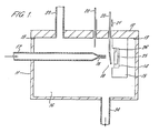
- Figure 1 shows a section through an abrasion testing unit particularly adapted for the measurement of low concentrations of metal particles in oils.
- the unit comprises a steel casing 11 having a Perspex (Registered Trade Mark) top 12 sealed thereto by oil seals 13 to define a chamber 16.
- a testing head 14 is mounted in a holder 15 positioned at one end of chamber 16.
- the head comprises an abradable film 25, and vacuum deposited gold terminals 26 for making electrical contact therewith.
- the electrical resistance of the film 25 is measured by a conventional D.C. bridge circuit (not shown).
- An oil supply pipe 17 is arranged so as to direct a jet of oil through the nozzle 18 onto the abradable film 25 of the head.
- a mask 19 is provided between the nozzle 18 and the head 14, to enable the commencement and termination of the abrasion of the film to be sharp.
- the mask 19 is secured to a control rod 20, which is slidable in the direction of the arrow 21, so that the mask 19 may be moved between the position shown, in which the film 25 is masked, and a raised position, in which abrasion of the film 25 by the oil is possible.
- the temperature within the chamber 16 is sensed by a temperature detector 22, e.g. thermo-couple.
- the temperature detector 22 is effective mainly when the apparatus is operated full of fluid (e.g. oil) under test.
- Fluid inlet and outlet pipes 23 and 24 respectively are provided to facilitate maintenance of the chamber in a fluid filled state.
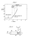
- Figure 5 is a schematic diagram of apparatus according to the invention in which a nozzle is provided for directing the fluid to be tested against the abradable film.
- the thin film of nichrome 27 is provided on a flattened area 28 of an alumina rod 29.
- a compensating film 30 is also provided on the alumina rod.
- Films 27 and 30 are produced by vapour deposition on the alumina rod using an appropriate mask.
- Gold terminals 31 are provided at each end of both films, again by vapor deposition using an appropriately formed mask.
- the electrical resistance of film 30 is approximately ten times that of film 27.
- Rod 29 is rotatable about its axis 32. In the position shown, a jet of fluid produced by nozzle 33 impinges directly on film 27 at 90°, to abrade the film. It has been found that the optimum angle of incidence for maximum abrasion is approximately 90°.
- Abrasion can be terminated by rotating rod 32 about its axis approximately 180°.
- film 30 is used as one limb of an A.C. resistance bridge, of which film 27 also forms a limb. Leads (not shown) are used to connect the bridge to film areas 31.
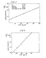
- the apparatus shown in Figure 1 was used to measure the abrasiveness of an oil (British Petroleum Reference No. CS461SO) doped with varying concentrations of chromium, having an average particle size of 20 ⁇ m.
- the orifice diameter of the nozzle was 2 m.m. and the distance from the nozzle to the film 10 m.m.
- the oil was delivered to the nozzle at a pressure of approximately 70 p.s.i. (4.8x10 5 N/m 2 ).
- the results are shown in Figures 2 and 3 in terms of the percentage resistance change over a period of approximately 5 minutes.
- liquid-based fluids i.e. slurries and oils
- the term "fluid” is used herein it its broadest sense, and includes gases
- the invention as claimed in its broadest sense includes a method of determining the abrasiveness of a gas containing particulate material, and thus indirectly the content of particles in the gas. Such determinations are of increasing value for monitoring atmospheric pollution (for example coal dust) in industrial environments.
- the fluid jet strikes the abradable film at an angle of 90°
- advantages can be obtained by arranging for the jet to strike the film at an oblique angle, for example at approximately 70°. In certain circumstances this can lead to more consistent abrasion of the film.
Landscapes
- General Health & Medical Sciences (AREA)
- Physics & Mathematics (AREA)
- Life Sciences & Earth Sciences (AREA)
- Chemical & Material Sciences (AREA)
- Analytical Chemistry (AREA)
- Biochemistry (AREA)
- Immunology (AREA)
- General Physics & Mathematics (AREA)
- Health & Medical Sciences (AREA)
- Pathology (AREA)
- Measurement Of Length, Angles, Or The Like Using Electric Or Magnetic Means (AREA)
- Investigating Or Analyzing Materials By The Use Of Electric Means (AREA)
- Polishing Bodies And Polishing Tools (AREA)
- Sliding-Contact Bearings (AREA)
Claims (14)
Priority Applications (1)
| Application Number | Priority Date | Filing Date | Title |
|---|---|---|---|
| AT80300846T ATE11455T1 (de) | 1979-03-21 | 1980-03-19 | Verfahren und vorrichtung zur bestimmung der abriebeigenschaften von fluiden, dieses verfahren verwendende methode zur kontrolle der abnutzung von lagern und mit dieser vorrichtung ausgestattete maschine. |
Applications Claiming Priority (2)
| Application Number | Priority Date | Filing Date | Title |
|---|---|---|---|
| GB7909953A GB2044935B (en) | 1979-03-21 | 1979-03-21 | Abrasion testing |
| GB7909953 | 1979-03-21 |
Publications (2)
| Publication Number | Publication Date |
|---|---|
| EP0016639A1 EP0016639A1 (de) | 1980-10-01 |
| EP0016639B1 true EP0016639B1 (de) | 1985-01-23 |
Family
ID=10504031
Family Applications (1)
| Application Number | Title | Priority Date | Filing Date |
|---|---|---|---|
| EP80300846A Expired EP0016639B1 (de) | 1979-03-21 | 1980-03-19 | Verfahren und Vorrichtung zur Bestimmung der Abriebeigenschaften von Fluiden, dieses Verfahren verwendende Methode zur Kontrolle der Abnutzung von Lagern und mit dieser Vorrichtung ausgestattete Maschine |
Country Status (5)
| Country | Link |
|---|---|
| US (1) | US4305278A (de) |
| EP (1) | EP0016639B1 (de) |
| AT (1) | ATE11455T1 (de) |
| DE (1) | DE3069994D1 (de) |
| GB (1) | GB2044935B (de) |
Families Citing this family (18)
| Publication number | Priority date | Publication date | Assignee | Title |
|---|---|---|---|---|
| US4337668A (en) * | 1980-12-05 | 1982-07-06 | Sun Gas Company | Orifice wear compensation |
| JPS61268969A (ja) * | 1985-05-24 | 1986-11-28 | ホシザキ電機株式会社 | オ−ガ式製氷機 |
| CA1261170A (en) * | 1985-10-11 | 1989-09-26 | Her Majesty The Queen In Right Of Canada As Represented By The Minister Of National Defence Of Her Majesty's Canadian Government | Ferromagnetic wear detector and method |
| GB2188154B (en) * | 1986-03-17 | 1989-11-15 | Fulmer Res Inst Ltd | Improvements in or relating to a method of and an apparatus for detecting the abrasive quality of a floppy disc |
| NO167879C (no) * | 1989-07-07 | 1991-12-18 | Norsk Hydro As | Sanddetektor. |
| NO176292C (no) * | 1990-10-17 | 1995-03-08 | Norsk Hydro As | Utstyr og fremgangsmåte for bestemmelse av mengden av partikkelformet materiale i en væske- og/eller gasström |
| US5495752A (en) * | 1995-02-01 | 1996-03-05 | Townsend; Johnnie V. | Erosion detector for a feed water steam nozzle |
| US5977782A (en) * | 1998-01-23 | 1999-11-02 | Cts Corporation | Fluid abrasion and/or corrosion sensors and method of sensing abrasion and/or corrosion |
| US6525334B1 (en) | 1999-11-19 | 2003-02-25 | Fleetguard, Inc. | System and method for detecting erosion caused by particles in a fluid |
| US7347768B1 (en) * | 2006-07-28 | 2008-03-25 | United States Of America As Represented By The Secretary Of The Army | Apparatus and method to test abrasion resistance of material using airborne particulate |
| GB2442489A (en) * | 2006-10-05 | 2008-04-09 | Ford Global Tech Llc | Engine or machine condition monitoring apparatus |
| NO327590B1 (no) * | 2007-03-05 | 2009-08-31 | Roxar Asa | Framgangsmate for maling av partikler i en fluidstrom, samt en probe for a gjennomfore denne framgangsmaten. |
| RU2601357C1 (ru) * | 2015-09-21 | 2016-11-10 | Федеральное государственное бюджетное образовательное учреждение высшего профессионального образования "Тихоокеанский государственный университет" | Аппарат для проверки стойкости антикоррозионных покрытий на истирание |
| CN105675424B (zh) * | 2016-03-04 | 2018-04-17 | 西安交通大学 | 一种水蚀试验及测控系统 |
| CN107782637B (zh) * | 2017-12-05 | 2023-10-03 | 广西玉柴机器股份有限公司 | 发动机缸孔磨损模拟试验装置 |
| JP7216960B2 (ja) * | 2019-05-17 | 2023-02-02 | 株式会社高速道路総合技術研究所 | 既設樹脂材の経年劣化評価方法及びその評価装置 |
| CN115094382B (zh) * | 2022-07-07 | 2023-08-15 | 佛山科学技术学院 | 一种用于金属或合金表面的复合薄膜、其制备方法及应用 |
| CN116124620B (zh) * | 2023-04-10 | 2023-06-27 | 西南交通大学 | 一种桥墩落石冲击与水沙磨蚀的试验装备及试验方法 |
Family Cites Families (17)
| Publication number | Priority date | Publication date | Assignee | Title |
|---|---|---|---|---|
| US3124771A (en) * | 1964-03-10 | Figure | ||
| GB683736A (en) * | 1950-01-27 | 1952-12-03 | Minnesota Mining & Mfg | Improvements in or relating to magnetic recording tape |
| US3067386A (en) | 1958-08-29 | 1962-12-04 | Standard Oil Co | Automatically temperature-compensated corrosion measurements |
| US3404556A (en) | 1965-06-18 | 1968-10-08 | Boris M. Kameras | Abrasion resistance testing apparatus |
| DE1521798A1 (de) | 1966-01-28 | 1969-10-23 | Ibm Deutschland | Verfahren zur staendigen,automatischen Kontrolle und Steuerung von AEtzprozessen oder galvanischen Prozessen |
| NL6712603A (de) * | 1967-09-15 | 1969-03-18 | ||
| US3599090A (en) * | 1969-06-30 | 1971-08-10 | Us Interior | Apparatus for detecting and measuring crevice corrosion |
| NL163834C (nl) | 1970-07-27 | 1980-05-16 | Textiltech Forsch | Werkwijze voor het vervaardigen van textielmateriaal, in het bijzonder dekens of dergelijke produkten, en textielmateriaal vervaardigd volgens de werkwijze. |
| NO134348C (de) * | 1971-02-22 | 1976-09-22 | Asea Ab | |
| GB1402413A (en) | 1971-09-02 | 1975-08-06 | Ici Ltd | Method of making an electrical resistance element |
| FR2184195A5 (de) * | 1972-05-10 | 1973-12-21 | Heckert Fritz Karl Marx | |
| US3958445A (en) | 1973-08-30 | 1976-05-25 | The Bendix Corporation | Proportional brake lining wear sensor |
| SE369636B (de) | 1973-11-28 | 1974-09-09 | Ericsson Telefon Ab L M | |
| CH573151A5 (de) | 1974-06-28 | 1976-02-27 | Bbc Sulzer Turbomaschinen | |
| FR2372425A1 (fr) * | 1976-11-26 | 1978-06-23 | Solvay | Procede et dispositif pour controler la nature corrosive, erosive et/ou incrustante d'un liquide |
| GB1559959A (en) * | 1978-02-03 | 1980-01-30 | Fulmer Res Inst Ltd | Method for the determination of the degree of abrasivencess of an article |
| US4176545A (en) * | 1978-06-16 | 1979-12-04 | Oddo Luigi G | Electronic engine wear detector |
-
1979
- 1979-03-21 GB GB7909953A patent/GB2044935B/en not_active Expired
-
1980
- 1980-03-10 US US06/128,800 patent/US4305278A/en not_active Expired - Lifetime
- 1980-03-19 EP EP80300846A patent/EP0016639B1/de not_active Expired
- 1980-03-19 DE DE8080300846T patent/DE3069994D1/de not_active Expired
- 1980-03-19 AT AT80300846T patent/ATE11455T1/de not_active IP Right Cessation
Non-Patent Citations (3)
| Title |
|---|
| D.M. BUCZEK (J. Vac. Sci. Technol. 15 (2) Mar/Apr. 1978 pp. 370-2 * |
| Kayed Labye Tables of Physical & Chemical Constants(14th Edition 1973) Longman pp. 165-6 * |
| L. Lassak & K. Hieber (Thin Solid Films 17 (1973), pp. 105-111) * |
Also Published As
| Publication number | Publication date |
|---|---|
| US4305278A (en) | 1981-12-15 |
| GB2044935B (en) | 1983-12-21 |
| GB2044935A (en) | 1980-10-22 |
| DE3069994D1 (en) | 1985-03-07 |
| EP0016639A1 (de) | 1980-10-01 |
| ATE11455T1 (de) | 1985-02-15 |
Similar Documents
| Publication | Publication Date | Title |
|---|---|---|
| EP0016639B1 (de) | Verfahren und Vorrichtung zur Bestimmung der Abriebeigenschaften von Fluiden, dieses Verfahren verwendende Methode zur Kontrolle der Abnutzung von Lagern und mit dieser Vorrichtung ausgestattete Maschine | |
| Kinnear et al. | Design, calibration and testing of transient thin film heat transfer gauges | |
| Fouletier et al. | Performance characteristics of conventional oxygen gauges | |
| US3333470A (en) | Method and apparatus for sensing fluid properties | |
| US3442773A (en) | Electrochemical gas measuring systems | |
| CN108981643A (zh) | 一种电缆导体或绝缘层截面积快速精确测量方法 | |
| Ju et al. | Deposition of Ga2O3 thin film for high-temperature oxygen sensing applications | |
| Frazer et al. | THE OSMOTIC PRESSURE OF SUCROSE SOLUTIONS AT 30°. | |
| Yim et al. | Electrical Conductivity of Molten Fluorides: I. Apparatus and Method | |
| Van Herwaarden et al. | Performance of integrated thermopile vacuum sensors | |
| Wonnell et al. | Activation volume for the interdiffusion of Ag‐Au multilayers | |
| GB2395561A (en) | Fluid temperature measurement | |
| Gregory et al. | A low TCR nanocomposite strain gage for high temperature aerospace applications | |
| Friehe | Fine-scale measurements of velocity, temperature, and humidity in the atmospheric boundary layer | |
| US3069332A (en) | Simplification in method of measuring corrision of electronic conductors by non-gaseous ionic conductors | |
| Meyerhof et al. | A modified Kelvin method for measuring contact potential differences | |
| Ayerdi et al. | Ceramic pressure sensor based on tantalum thin film | |
| US3110173A (en) | Moisture content monitoring | |
| Sobe et al. | Deposition of Cr-Si thin films by reactive plasmatron-magnetron sputtering | |
| US3094865A (en) | Conductometric corrosion measurement system | |
| JP2946931B2 (ja) | 高温高湿型原子間力顕微鏡及び化学反応の観察・定量化方法 | |
| SU914986A1 (ru) | Способ неразрушаюшего контроля чистоты поверхности металлов 1 | |
| Jessen et al. | A new method for manufacture of thin film heat flux gauges | |
| Yurke et al. | Cryogenic piezoelectric displacement tester | |
| Arshak et al. | Characterisation of a thin-film/thick-film strain gauge sensor on stainless steel |
Legal Events
| Date | Code | Title | Description |
|---|---|---|---|
| PUAI | Public reference made under article 153(3) epc to a published international application that has entered the european phase |
Free format text: ORIGINAL CODE: 0009012 |
|
| AK | Designated contracting states |
Designated state(s): AT BE CH DE FR GB IT LU NL SE |
|
| 17P | Request for examination filed |
Effective date: 19810319 |
|
| ITF | It: translation for a ep patent filed | ||
| GRAA | (expected) grant |
Free format text: ORIGINAL CODE: 0009210 |
|
| RBV | Designated contracting states (corrected) |
Designated state(s): AT BE CH DE FR IT LU NL SE |
|
| AK | Designated contracting states |
Designated state(s): AT BE CH DE FR IT LU NL SE |
|
| PG25 | Lapsed in a contracting state [announced via postgrant information from national office to epo] |
Ref country code: SE Effective date: 19850123 Ref country code: NL Effective date: 19850123 Ref country code: AT Effective date: 19850123 |
|
| REF | Corresponds to: |
Ref document number: 11455 Country of ref document: AT Date of ref document: 19850215 Kind code of ref document: T |
|
| REF | Corresponds to: |
Ref document number: 3069994 Country of ref document: DE Date of ref document: 19850307 |
|
| PG25 | Lapsed in a contracting state [announced via postgrant information from national office to epo] |
Ref country code: LU Free format text: LAPSE BECAUSE OF NON-PAYMENT OF DUE FEES Effective date: 19850331 |
|
| ET | Fr: translation filed | ||
| NLV1 | Nl: lapsed or annulled due to failure to fulfill the requirements of art. 29p and 29m of the patents act | ||
| PLBE | No opposition filed within time limit |
Free format text: ORIGINAL CODE: 0009261 |
|
| STAA | Information on the status of an ep patent application or granted ep patent |
Free format text: STATUS: NO OPPOSITION FILED WITHIN TIME LIMIT |
|
| 26N | No opposition filed | ||
| PG25 | Lapsed in a contracting state [announced via postgrant information from national office to epo] |
Ref country code: CH Effective date: 19870331 |
|
| BERE | Be: lapsed |
Owner name: FULMER RESEARCH INSTITUTE LIMITED Effective date: 19870331 |
|
| REG | Reference to a national code |
Ref country code: CH Ref legal event code: PL |
|
| PG25 | Lapsed in a contracting state [announced via postgrant information from national office to epo] |
Ref country code: BE Effective date: 19890331 |
|
| PGFP | Annual fee paid to national office [announced via postgrant information from national office to epo] |
Ref country code: FR Payment date: 19910322 Year of fee payment: 12 |
|
| PGFP | Annual fee paid to national office [announced via postgrant information from national office to epo] |
Ref country code: DE Payment date: 19910523 Year of fee payment: 12 |
|
| PG25 | Lapsed in a contracting state [announced via postgrant information from national office to epo] |
Ref country code: FR Effective date: 19921130 |
|
| PG25 | Lapsed in a contracting state [announced via postgrant information from national office to epo] |
Ref country code: DE Effective date: 19921201 |
|
| REG | Reference to a national code |
Ref country code: FR Ref legal event code: ST |