EP0016331B1 - Energie absorbierende Torsionskupplung - Google Patents
Energie absorbierende Torsionskupplung Download PDFInfo
- Publication number
- EP0016331B1 EP0016331B1 EP80100675A EP80100675A EP0016331B1 EP 0016331 B1 EP0016331 B1 EP 0016331B1 EP 80100675 A EP80100675 A EP 80100675A EP 80100675 A EP80100675 A EP 80100675A EP 0016331 B1 EP0016331 B1 EP 0016331B1
- Authority
- EP
- European Patent Office
- Prior art keywords
- rim
- hub
- rollers
- belt
- energy
- Prior art date
- Legal status (The legal status is an assumption and is not a legal conclusion. Google has not performed a legal analysis and makes no representation as to the accuracy of the status listed.)
- Expired
Links
- 229920001971 elastomer Polymers 0.000 claims description 50
- 239000000806 elastomer Substances 0.000 claims description 50
- 238000002844 melting Methods 0.000 claims description 33
- 230000008018 melting Effects 0.000 claims description 33
- LYCAIKOWRPUZTN-UHFFFAOYSA-N Ethylene glycol Chemical compound OCCO LYCAIKOWRPUZTN-UHFFFAOYSA-N 0.000 claims description 20
- 150000002148 esters Chemical group 0.000 claims description 16
- WERYXYBDKMZEQL-UHFFFAOYSA-N butane-1,4-diol Chemical compound OCCCCO WERYXYBDKMZEQL-UHFFFAOYSA-N 0.000 claims description 10
- WGCNASOHLSPBMP-UHFFFAOYSA-N hydroxyacetaldehyde Natural products OCC=O WGCNASOHLSPBMP-UHFFFAOYSA-N 0.000 claims description 10
- 239000002131 composite material Substances 0.000 claims description 9
- 125000002887 hydroxy group Chemical group [H]O* 0.000 claims description 6
- 150000002009 diols Chemical class 0.000 claims description 5
- OFOBLEOULBTSOW-UHFFFAOYSA-N Malonic acid Chemical compound OC(=O)CC(O)=O OFOBLEOULBTSOW-UHFFFAOYSA-N 0.000 claims description 4
- KKEYFWRCBNTPAC-UHFFFAOYSA-N Terephthalic acid Chemical compound OC(=O)C1=CC=C(C(O)=O)C=C1 KKEYFWRCBNTPAC-UHFFFAOYSA-N 0.000 claims description 4
- 125000003178 carboxy group Chemical group [H]OC(*)=O 0.000 claims description 3
- 239000011159 matrix material Substances 0.000 claims description 3
- 229920000233 poly(alkylene oxides) Polymers 0.000 claims description 3
- 230000005540 biological transmission Effects 0.000 description 13
- -1 poly(tetramethylene oxide) Polymers 0.000 description 8
- WOZVHXUHUFLZGK-UHFFFAOYSA-N dimethyl terephthalate Chemical compound COC(=O)C1=CC=C(C(=O)OC)C=C1 WOZVHXUHUFLZGK-UHFFFAOYSA-N 0.000 description 6
- 230000035939 shock Effects 0.000 description 6
- 239000012530 fluid Substances 0.000 description 5
- 238000013016 damping Methods 0.000 description 4
- OKKJLVBELUTLKV-UHFFFAOYSA-N Methanol Chemical compound OC OKKJLVBELUTLKV-UHFFFAOYSA-N 0.000 description 3
- 239000002253 acid Substances 0.000 description 3
- 230000008878 coupling Effects 0.000 description 3
- 238000010168 coupling process Methods 0.000 description 3
- 238000005859 coupling reaction Methods 0.000 description 3
- 239000000446 fuel Substances 0.000 description 3
- 238000009998 heat setting Methods 0.000 description 3
- 230000007935 neutral effect Effects 0.000 description 3
- 229920001634 Copolyester Polymers 0.000 description 2
- NIQCNGHVCWTJSM-UHFFFAOYSA-N Dimethyl phthalate Chemical compound COC(=O)C1=CC=CC=C1C(=O)OC NIQCNGHVCWTJSM-UHFFFAOYSA-N 0.000 description 2
- 239000003963 antioxidant agent Substances 0.000 description 2
- 125000004122 cyclic group Chemical group 0.000 description 2
- DMBHHRLKUKUOEG-UHFFFAOYSA-N diphenylamine Chemical compound C=1C=CC=CC=1NC1=CC=CC=C1 DMBHHRLKUKUOEG-UHFFFAOYSA-N 0.000 description 2
- 238000006073 displacement reaction Methods 0.000 description 2
- 238000010438 heat treatment Methods 0.000 description 2
- QQVIHTHCMHWDBS-UHFFFAOYSA-N isophthalic acid Chemical compound OC(=O)C1=CC=CC(C(O)=O)=C1 QQVIHTHCMHWDBS-UHFFFAOYSA-N 0.000 description 2
- 150000002531 isophthalic acids Chemical class 0.000 description 2
- 238000000034 method Methods 0.000 description 2
- 239000000203 mixture Substances 0.000 description 2
- XNGIFLGASWRNHJ-UHFFFAOYSA-N phthalic acid Chemical compound OC(=O)C1=CC=CC=C1C(O)=O XNGIFLGASWRNHJ-UHFFFAOYSA-N 0.000 description 2
- 150000003022 phthalic acids Chemical class 0.000 description 2
- 229920000642 polymer Polymers 0.000 description 2
- 150000003504 terephthalic acids Chemical class 0.000 description 2
- 229920001169 thermoplastic Polymers 0.000 description 2
- 239000004416 thermosoftening plastic Substances 0.000 description 2
- 244000048879 Funtumia elastica Species 0.000 description 1
- 239000006096 absorbing agent Substances 0.000 description 1
- 230000003321 amplification Effects 0.000 description 1
- 230000003078 antioxidant effect Effects 0.000 description 1
- 239000003054 catalyst Substances 0.000 description 1
- 238000006243 chemical reaction Methods 0.000 description 1
- 230000006835 compression Effects 0.000 description 1
- 238000007906 compression Methods 0.000 description 1
- 230000008602 contraction Effects 0.000 description 1
- 238000001816 cooling Methods 0.000 description 1
- 230000006866 deterioration Effects 0.000 description 1
- 125000005266 diarylamine group Chemical group 0.000 description 1
- VNGOYPQMJFJDLV-UHFFFAOYSA-N dimethyl benzene-1,3-dicarboxylate Chemical compound COC(=O)C1=CC=CC(C(=O)OC)=C1 VNGOYPQMJFJDLV-UHFFFAOYSA-N 0.000 description 1
- FBSAITBEAPNWJG-UHFFFAOYSA-N dimethyl phthalate Natural products CC(=O)OC1=CC=CC=C1OC(C)=O FBSAITBEAPNWJG-UHFFFAOYSA-N 0.000 description 1
- 229960001826 dimethylphthalate Drugs 0.000 description 1
- 230000000694 effects Effects 0.000 description 1
- 238000001125 extrusion Methods 0.000 description 1
- 238000010304 firing Methods 0.000 description 1
- 230000004927 fusion Effects 0.000 description 1
- 239000000463 material Substances 0.000 description 1
- 239000002184 metal Substances 0.000 description 1
- OJURWUUOVGOHJZ-UHFFFAOYSA-N methyl 2-[(2-acetyloxyphenyl)methyl-[2-[(2-acetyloxyphenyl)methyl-(2-methoxy-2-oxoethyl)amino]ethyl]amino]acetate Chemical compound C=1C=CC=C(OC(C)=O)C=1CN(CC(=O)OC)CCN(CC(=O)OC)CC1=CC=CC=C1OC(C)=O OJURWUUOVGOHJZ-UHFFFAOYSA-N 0.000 description 1
- 238000012986 modification Methods 0.000 description 1
- 230000004048 modification Effects 0.000 description 1
- 238000003199 nucleic acid amplification method Methods 0.000 description 1
- 229920001451 polypropylene glycol Polymers 0.000 description 1
- 238000011084 recovery Methods 0.000 description 1
- 230000000284 resting effect Effects 0.000 description 1
Images


Classifications
-
- F—MECHANICAL ENGINEERING; LIGHTING; HEATING; WEAPONS; BLASTING
- F16—ENGINEERING ELEMENTS AND UNITS; GENERAL MEASURES FOR PRODUCING AND MAINTAINING EFFECTIVE FUNCTIONING OF MACHINES OR INSTALLATIONS; THERMAL INSULATION IN GENERAL
- F16D—COUPLINGS FOR TRANSMITTING ROTATION; CLUTCHES; BRAKES
- F16D3/00—Yielding couplings, i.e. with means permitting movement between the connected parts during the drive
- F16D3/50—Yielding couplings, i.e. with means permitting movement between the connected parts during the drive with the coupling parts connected by one or more intermediate members
- F16D3/52—Yielding couplings, i.e. with means permitting movement between the connected parts during the drive with the coupling parts connected by one or more intermediate members comprising a continuous strip, spring, or the like engaging the coupling parts at a number of places
-
- F—MECHANICAL ENGINEERING; LIGHTING; HEATING; WEAPONS; BLASTING
- F16—ENGINEERING ELEMENTS AND UNITS; GENERAL MEASURES FOR PRODUCING AND MAINTAINING EFFECTIVE FUNCTIONING OF MACHINES OR INSTALLATIONS; THERMAL INSULATION IN GENERAL
- F16D—COUPLINGS FOR TRANSMITTING ROTATION; CLUTCHES; BRAKES
- F16D3/00—Yielding couplings, i.e. with means permitting movement between the connected parts during the drive
- F16D3/02—Yielding couplings, i.e. with means permitting movement between the connected parts during the drive adapted to specific functions
- F16D3/12—Yielding couplings, i.e. with means permitting movement between the connected parts during the drive adapted to specific functions specially adapted for accumulation of energy to absorb shocks or vibration
-
- Y—GENERAL TAGGING OF NEW TECHNOLOGICAL DEVELOPMENTS; GENERAL TAGGING OF CROSS-SECTIONAL TECHNOLOGIES SPANNING OVER SEVERAL SECTIONS OF THE IPC; TECHNICAL SUBJECTS COVERED BY FORMER USPC CROSS-REFERENCE ART COLLECTIONS [XRACs] AND DIGESTS
- Y10—TECHNICAL SUBJECTS COVERED BY FORMER USPC
- Y10S—TECHNICAL SUBJECTS COVERED BY FORMER USPC CROSS-REFERENCE ART COLLECTIONS [XRACs] AND DIGESTS
- Y10S464/00—Rotary shafts, gudgeons, housings, and flexible couplings for rotary shafts
- Y10S464/902—Particular material
- Y10S464/903—Nonmetal
Definitions
- Compression spring systems have been used for the torque cushioning portion of the lock-up clutch in an automotive vehicle, but their very presence, i.e., the space they occupy, plus their necessary push rods, severely limits the amount of differential rotation permitted between the two shafts.
- Such systems are hard cushions with correspondingly high natural frequencies of vibration and, therefore, they perform poorly in response to sudden power surges and do little toward the damping of external vibrations.
- Prior art couplings (DE-B-10 86 495) of the mentioned kind permit only low rotation to full torque (on the order of 20 to 40° max.). Higher rotation to full torque, however, is important because it provides a softer cushion more suitable for damping of drive line vibration of any kind. Also, the outer pulley pair opposite each hub pulley cannot be separated by variable distances in order to affect the shape of the torque response curve. Pulleys close together produce a device with insufficient cushioning characteristics. This disadvantageous effect is increased by the material of which the belts are made, f.i. rubber (FR-A-11 20269).
- the present invention is particularly suitable for use in automatic transmissions in automotive vehicles since it provides a means for substantially eliminating vibrations and shock due to power surges from the engine, misfires and sudden changes in demand load for propulsion.
- the present. invention provides for substantially eliminating fluid slip in the torque converter. Fluid slip results in energy loss, and thence, in heat buildup and excess fuel consumption.
- the present invention when used in automotive vehicles equipped with automatic transmissions, can result in substantially lower fuel consumption.
- the apparatus described herein when used as an energy-absorbing torque cushion, offers a lower natural frequency of vibration compared to metal spring systems farther removed from the range of the frequencies associated with automotive engines, drive shaft, gear and the like and, therefore, results in a smoother riding vehicle.
- the apparatus of the present invention will be described primarily in relation to a lock-up clutch in an automatic transmission for an automotive vehicle it can be used in other applications.
- the present invention is directed to an energy-absorbing torque transmitter comprising a hub member and a rim member, one of which is connected to an output shaft, the other to an input shaft, the hub member having hub journal means mounted thereon the rim member of larger diameter having rim journal means mounted thereon, said hub and rim members are circumferentially arranged around their common axis and being operably connected by at least one belt through the hub and rim journal means characterised in that the hub journal means and rim journal means are rollers and the number of rim rollers is at least twice the number of hub rollers and the belt is a composite belt of two copolyetherester elastomers having different melting points trained over hub and rim rollers, the higher melting point copolyetherester elastomer is in the form of strands, tapes or films which are monoaxially oriented in the direction of their length, and the lower meltilng point copolyetherester elastomer is bonded thereto in an unoriented form as a matrix surrounding the individual strands,
- the device permits high rotation to full torque (on the order of 60-80°) and this provides a softer cushion suitable for damping of drive line vibration of any kind.
- the pulleys can be separated by variable distances, so that they may be separated widely and this produces a very soft device in the vicinity of neutral, much softer than can be produced with the known radial devices.
- the device can be designed to provide torque vs. rotational displacement curves to fit a wide variety of needs.
- the oriented elastomeric belt can be stretched in the energy-absorbing torque transmitter from about 2-60% of its original length, and usually for most applications 5-30%, when force is applied.
- the belt returns to substantially its original length when force is removed.
- An endless belt connects hub rollers and rim rollers, or a plurality of belts connect hub rollers and rim rollers.
- the belt can be an endless belt or merely a strap having two free ends.
- the belt is a composite wherein layers of oriented copolyetherester elastomer are substantially encapsulated within a lower melting point copolyetherester elastomer.
- the belt functions as a torque cushioning device on the sudden application of forces which result in relative rotation between hub member and rim member as from the sudden lock-up of a torque converter lock-up clutch.
- the elastomeric belt is stretched just enough to handle the current torque requirement and returns substantially to its original length when force is removed.
- the transmission fluid present in the housing of the torque converter does not cause appreciable deterioration of the oriented copolyetherester belt at operating temperatures under cyclic strain.
- the hub member is an inner rotor with spaced radially disposed walls between which hub rollers are mounted, the hub rollers being on shafts mounted in the walls.
- the rim member is an outer rotor with spaced, inwardly projecting walls between which rim rollers are mounted. The walls being aligned with the walls of the inner rotor and rim rollers are mounted between the walls on shafts mounted in the walls.
- a plurality of guide rollers can be mounted on said rim member and a radially off-set from rim rollers to allow use of a longer belt, thereby lowering the relative extension of the elastomeric belt for a given relative rotation of the hub and rim member.
- a plurality of push rollers can be mounted on the hub member outwardly of the hub rollers adjacent to the copolyetherester elastomer belt and aligned substantially radially with rim rollers.
- the apparatus of the present invention is especially suitable for use as a torque cushion ahead of the gears in an automotive transmission to operatively and softly connect the transmission shaft directly to the engine drive shaft, coincidentally locking out the funtionality of the torque converter of fluid coupling which might otherwise be involved.
- hub member 10 is adapted to be coupled by spline 23 to one end of a shaft, which will be assumed to be a driven shaft or output shaft 14, such as in an automobile, the torque converter output or transmission input shaft.
- Rim member 12 is adapted to be coupled by spline 24 to one end of a second shaft, which will be considered the driving shaft or input shaft 16, such as the engine output or torque converter input shaft. It is understood that it is immaterial whether the hub member or rim member is employed as the driver.
- the rim member 12 of larger diameter than hub member 10 has a plurality of rim rollers 11, preferably in pairs, mounted on walls 21 of rim member 12 near the circumference.
- said rim member 12 comprises an outer rotor 20 with spaced inwardly projecting walls 21 between which rim rollers 11 are mounted, one of the walls of outer rotor 20 being rim cover plate 25.
- a plurality of hub rollers 15 are mounted on hub member 10.
- hub member 10 comprises an inner rotor 18 with spaced radially disposed walls 19 between which hub rollers 15 are mounted, one of the walls of inner rotor 18 being hub cover plate 26.
- the hub and rim rollers preferably are pulleys that are rotatable with stretch of the elastomeric belt, but the pulleys can be fixed and the elastomeric belt can slide over them.
- the torque transmitter has at least two hub rollers 15 mounted on hub member 10 and a plurality of rim rollers 11 on rim member 12.
- the hub members have at least two hub rollers and the rim members have at least two pairs of rim rollers, or twice as many rim rollers as hub rollers, as illustrated in Fig. 2.
- rim and hub rollers form triangular arrangements with each other, usually an isosceles triangle in the neutral or resting position, and the number of rim rollers is twice the number of hub rollers.
- the rollers are circumferentially arranged around the common axis of hub and rim members with rim rollers 11 on a larger circle than hub rollers 15.
- Copolyetherester elastomer belt 13 that is trained over rim rollers 11 and hub roller 15 can be a single endless belt as in Fig. 1, or a plurality of endless belts, as in Fig. 3, or a plurality of straps fastened to rim member 12 by pins 22 as shown in Fig. 2.
- guide rollers 17 are mounted on the rim member 12 and radially off-set from rim rollers 11 so as to increase the neutral or at-rest length of thermoplastic copolyetherester elastomer belt 13, thus lowering the relative extension of the elastomeric belt for a given relative rotation of hub to rim.
- reverse characteristics of the energy-absorbing torque transmitter can differ from the forward characteristics by means of push rollers 27 mounted on hub member 10 outwardly of hub rollers 15 adjacent or in contact with copolyetherester elastomer belt 13 that joins hub rollers 15 to rim rollers 11.
- Push rollers 27 are aligned substantially radially with the rim rollers. This provides greater torque in one direction for a given degree of relative motion between rim member and hub member than in the opposite direction. This full torque development occurs with fewer degrees of rotation in reverse motion of hub member relative to rim member than is required in the forward motion direction.
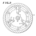
- Guide rollers 17 shown in Fig. 5 serve as do those of Fig. 4, but with the additional purpose of removing the elastomeric belt from possible interference with other rollers.
- the rim rollers 11 can be placed at various distances along the circumference of the circle they make on rim member 12. The larger the distance between rim rollers 11 of each given pair, as shown in Fig. 3, the softer is its cushioning at low levels of torque. On the other hand, the shorter the distance between rim rollers of each pair, as shown in Fig. 2, the harder is its cushioning at low levels of torque. Usually the two rollers of the pair are separated from each other by about 10-120 0 , depending upon the initial softness desired.
- the oriented copolyetherester elastomer belt 13 does not deteriorate and retains its elasticity and strength when immersed in transmission fluid at operating temperatures used in an automatic transmission system connecting the drive shaft to the engine shaft.
- the uniqueness of the oriented copolyetherester elastomeric belt lies in its exceptionally high stress development capability coupled with its potential for excellent recovery from high strains. This means that high forces can be developed with small cross-sections and that high extensions and, therefore, high degrees of rotation (for torque development and softer cushioning) can be achieved with minimal lengths of belt.
- the elastomeric belt is made of a polymer that consists essentially of a multiplicity of recurring long-chain and short-chain ester units joined head-to-tail through ester linkages, said long-chain ester units being represented by the structure: and said short-chain ester units being represented by the structure: wherein:
- the copolyetheresters can be made conveniently by a conventional ester interchange reaction.
- a preferred procedure involves heating the dicarboxylic acid or ester thereof, e.g., dimethyl ester of terephthalic acid, phthalic or isophthalic acid, with a long-chain glycol, e.g., poly(tetramethylene oxide) glycol having a molecular weight of about 600-2000 and a molar excess of diol, e.g., 1,4-butanediol, in the presence of a catalyst at about 150°-260°C and a pressure of 50-500 kPa, preferably ambient pressure, while distilling off methanol formed by the ester interchange.
- a catalyst at about 150°-260°C and a pressure of 50-500 kPa, preferably ambient pressure
- G is the group remaining after removal of hydroxyl groups from poly(tetramethylene oxide) glycol having a molecular weight of about 600-2000; R is the group remaining after removal of carboxyl groups from phthalic, terephthalic or isophthalic acids or mixtures thereof, and D is the group remaining after removal of hydroxyl groups from 1,4-butanediol.
- At least 1.1 mole of diol should be present for each mole of acid, preferably at least about 1.25 mole of diol for each mole of acid.
- the long-chain glycol should be present in the amount of about 0.0025 to 0.85 mole per mole of dicarboxylic acid, preferably 0.01 to 0.6 mole per mole of acid.
- Preferred copolyesters are those prepared from dimethyl terephthalate, 1,4-butanediol, and poly(tetramethylene oxide) glycol having a molecular weight of about 600-1500.
- dimethyl terephthalate, 1,4-butanediol, and poly(tetramethylene oxide) glycol having a molecular weight of about 600-1500.
- up to about 30 mole percent and preferably 5-20 mole percent of the dimethyl terephthalate in these polymers can be replaced by dimethyl phthalate or dimethyl isophthalate.
- Other preferred copolyesters are those prepared from dimethyl terephthalate, 1,4-butanediol, and poly(propylene oxide) glycol having a molecular weight of about 600-1600.
- the copolyetherester compositions may also contain up to about 5 weight percent of an antioxidant, e.g., between about 0.2 and 5 weight percent, preferably between about 0.5 and 3 weight percent.
- an antioxidant e.g., between about 0.2 and 5 weight percent, preferably between about 0.5 and 3 weight percent.
- the most preferred antioxidants are diaryl amines such as 4,4'-bis-( ⁇ , ⁇ -dimethylbenzyl) diphenylamine.
- Oriented copolyetherester belts can be formed in a number of ways.
- the elastomer can be molded in the form of a torus in a conventional manner and the article oriented by stretching, heat setting and cooling. Stretching is accomplished by any convenient means to achieve at least 300% in excess of its original length and preferably at least 400% at a temperature below its melting point by at least 10°C. It is maintained at that length and brought to or maintained at a heat setting temperature between 85° and 10°C below its melting point. It is then cooled to a temperature below the heat setting temperature by at least 55°C.
- the oriented thermoplastic copolyetherester elastomers belt is composed of two copolyetherester elastomer having different melting points.
- the higher melting point copolyetherester elastomer is in the form of strands, tapes or films which are monoaxially oriented in the direction of their length, or are biaxially oriented, and the lower melting copolyetherester elastomer is bonded thereto in an unoriented form for example, as a matrix surrounding the individual strand, tapes or films of oriented copolyetherester elastomer.
- the lower melting elastomer binds the oriented strands, tapes or films into a unitary belt.
- the belt is a composite having several layers of oriented copolyetherester elastomer tape substantially alternating with layers of lower melting point unoriented copolyetherester elastomer.
- Each layer of tape of the higher melting point encapsulated elastomer forms a single, convenient unit for fabricating a composite belt.
- the composite belt can be made in a number of ways.
- the two copolyetherester elastomers having melting points differing by at least 20°C are coextruded into thin tapes, e.g., 0.1-0.5 mm thick.
- the thin tapes of copolyetherester are oriented by stretching by at least 300% of their original length and then heat-set at a'temperature of 85°C-10°C below the melting point of the higher melting oriented copolyetherester elastomer.
- the tape is then wrapped around a mandrel until a sufficient number of layers has been built up to obtain the desired thickness, for example, about 10-30 layers.
- the article is heated to a temperature above the melting point of the lower melting point copolyetherester elastomer but below the melting point of the higher melting point copolyetherester elastomer by at least about 10°C.
- the lower melting point copolyetherester becomes fused in the heating step and adheres together adjacent layers of oriented higher melting point copolyetherester.
- the article can also be heat set during the heat fusion step. The procedure for forming the composite article is further described in U.S. Patent 4,136,715.
- the belt can be fabricated from strands of elastomer.
- an oriented strand of higher melting point copolyetherester elastomer is drawn through a molten bath of lower melting point copolyetherester elastomer at a temperature above the melting point of the lower melting point copolyetherester elastomer but below that of the oriented copolyetherester elastomer.
- the strand of higher melting point oriented copolyetherester elastomer can be encapsulated by simultaneous extrusion with the lower melting point copolyetherester elastomer and then by stretching the extrudate to orient the copolyetheresters.
- a composite belt of copolyetherester elastomer wherein the oriented elastomer is substantially encapsulated within the unoriented elastomer, can be prepared by laying up the appropriate number of layers of elastomer around end restraints for a belt having the form of a strap, or around a drum for an endless belt. The lay-up is heated to melt the lower melting point encapsulating elastomer without melting the higher melting point oriented core or encapsulated elastomer. The lay-up is cooled to solidify the lower melting point elastomer that bonds the layers together. In the case of a belt that is a strap, external pressure can be applied to the plied-up stack during bonding to assure good melt flow and joining of the bonded layers.
- Fig. 1-A shows the energy-absorbing torque transmitter at rest
- Fig. 1-C shows the apparatus when torque is applied.
- This lengthening causes a corresponding restoring force in oriented elastomeric belt 13, which in turn is communicated to the hub rollers 15 and thence to hub member 10.
- This force causes a clockwise torque in the driven or output shaft 14, which increases as the relative motion of the rim member 12 with respect to the hub member 10 continues.
- Hub member 10 starts to turn when the torque caused by the stretching of oriented elastomeric belt 13 becomes large enough to overcome the initial resisting torque in the output shaft 14. At first it turns more slowly than the input shaft 16 and the relative displacement between the hub and the rim members continues to increase. The ensuing increasing torque causes the rotation of the output shaft 14 to speed up gradually until the torque supplied by the stretching oriented elastomer belt balances the torque caused by the load on the output shaft 14. At this point, the relative motion of the hub and rim members with their attached shafts ceases, and they turn in unison. The two shafts are said to be locked together.
- the torque transmitter acts similarly when translstory forces act on the machinery to which it is attached, as for instance, misfires, vibrations, or other sudden shocks. These are immed- diately compensated for by relative motion of the input and output shafts and, in turn, by corresponding extension or contraction of the oriented elastomer belt. The elastic nature of the latter then permits a gradual shock-free return of the original condition, i.e., "locked" rotation of the input and output shafts.
Landscapes
- Engineering & Computer Science (AREA)
- General Engineering & Computer Science (AREA)
- Mechanical Engineering (AREA)
- Pulleys (AREA)
- Transmission Devices (AREA)
Claims (11)


Applications Claiming Priority (2)
| Application Number | Priority Date | Filing Date | Title |
|---|---|---|---|
| US06/013,193 US4266409A (en) | 1979-02-16 | 1979-02-16 | Energy-absorbing torque transmitter |
| US13193 | 1979-02-16 |
Publications (2)
| Publication Number | Publication Date |
|---|---|
| EP0016331A1 EP0016331A1 (de) | 1980-10-01 |
| EP0016331B1 true EP0016331B1 (de) | 1983-06-22 |
Family
ID=21758742
Family Applications (1)
| Application Number | Title | Priority Date | Filing Date |
|---|---|---|---|
| EP80100675A Expired EP0016331B1 (de) | 1979-02-16 | 1980-02-11 | Energie absorbierende Torsionskupplung |
Country Status (7)
| Country | Link |
|---|---|
| US (1) | US4266409A (de) |
| EP (1) | EP0016331B1 (de) |
| JP (2) | JPS55109844A (de) |
| AU (1) | AU532958B2 (de) |
| BR (1) | BR8000811A (de) |
| CA (1) | CA1141557A (de) |
| DE (1) | DE3063804D1 (de) |
Families Citing this family (16)
| Publication number | Priority date | Publication date | Assignee | Title |
|---|---|---|---|---|
| US4342806A (en) * | 1980-06-09 | 1982-08-03 | E. I. Du Pont De Nemours And Company | Composite elastomeric spring belt |
| US4378220A (en) * | 1980-06-09 | 1983-03-29 | E. I. Du Pont De Nemours And Company | Apparatus for and method of coupling shafts |
| JPS5972321U (ja) * | 1982-11-08 | 1984-05-16 | トヨタ自動車株式会社 | クラツチデイスク |
| JPS60146922A (ja) * | 1984-01-06 | 1985-08-02 | Daikin Mfg Co Ltd | 捩りダンパ−デイスク |
| DE4408474C1 (de) * | 1994-03-12 | 1995-04-20 | Freudenberg Carl Fa | Drehelastische Kupplung |
| EP1114917A3 (de) | 2000-01-04 | 2002-03-06 | TCG UNITECH Aktiengesellschaft | Vorrichtung zur Drehwinkelverstellung |
| DE102010048567B3 (de) * | 2010-10-18 | 2012-04-12 | Deutsches Zentrum für Luft- und Raumfahrt e.V. | Nachgiebige Getriebeeinheit |
| RU2614160C2 (ru) * | 2016-03-13 | 2017-03-23 | Александр Васильевич Дегтярев | Тормозная муфта с универсальной самоцентрирующейся системой |
| RU2629462C2 (ru) * | 2016-03-14 | 2017-08-29 | Александр Васильевич Дегтярев | Способ торможения с универсальной самоцентрирующейся системой |
| RU2613931C2 (ru) * | 2016-03-17 | 2017-03-22 | Александр Васильевич Дегтярев | Муфта с универсальной самоцентрирующейся системой |
| RU2613954C2 (ru) * | 2016-04-10 | 2017-03-22 | Александр Васильевич Дегтярев | Обгонная муфта с универсальной самоцентрирующейся системой |
| RU2632370C2 (ru) * | 2016-07-10 | 2017-10-04 | Александр Васильевич Дегтярев | Электромагнитный тормоз с универсальной самоцентрирующейся системой |
| RU2632383C2 (ru) * | 2016-08-17 | 2017-10-04 | Александр Васильевич Дегтярев | Способ торможения при использовании универсальной самоцентрирующейся системы. |
| RU2639363C2 (ru) * | 2016-10-03 | 2017-12-21 | Александр Васильевич Дегтярев | Способ торможения с обратной связью |
| CN111379823B (zh) * | 2018-12-27 | 2023-03-24 | 法雷奥凯佩科液力变矩器(南京)有限公司 | 用于机动车辆的传动系统的扭转减振器 |
| CN109869443A (zh) * | 2018-12-29 | 2019-06-11 | 株式会社法雷奥凯佩科 | 橡胶带减震器 |
Family Cites Families (16)
| Publication number | Priority date | Publication date | Assignee | Title |
|---|---|---|---|---|
| US643081A (en) * | 1898-04-29 | 1900-02-06 | Mary Ann Bullock | Coupling for shafts. |
| US703582A (en) * | 1902-02-26 | 1902-07-01 | P H & F M Roots Company | Flexible shaft-coupling. |
| US989064A (en) * | 1908-09-08 | 1911-04-11 | Felten & Guilleaume Lahmeyerwe | Elastic coupling. |
| US1591242A (en) * | 1923-05-07 | 1926-07-06 | Palmer Bee Co | Flexible coupling |
| US1522980A (en) * | 1923-05-08 | 1925-01-13 | Layne & Bowler Corp | Rotary-pump mechanism |
| US2778663A (en) * | 1948-09-03 | 1957-01-22 | Bolton John W & Sons Inc | Coupling for split hub and shaft |
| DE1086495B (de) * | 1952-12-22 | 1960-08-04 | Flender A F & Co | Elastische Wellenkupplung |
| FR1120269A (fr) * | 1955-01-24 | 1956-07-03 | Perrussel Freres Ets | Accouplement élastique à flexibilité variable |
| US2858855A (en) * | 1955-11-29 | 1958-11-04 | Picanol Jaime | Method and apparatus for facilitating the starting of looms without changing the pick |
| DK89078C (da) * | 1956-05-17 | 1960-05-30 | Krueger As I | Eftergivelig kobling. |
| FR1198842A (fr) * | 1958-02-12 | 1959-12-09 | Accouplement élastique | |
| US3766146A (en) * | 1971-03-18 | 1973-10-16 | Du Pont | Segmented thermoplastic copolyester elastomers |
| US4012962A (en) * | 1974-07-22 | 1977-03-22 | Dayco Corporation | Endless power transmission belt structure |
| JPS5419027B2 (de) * | 1974-09-26 | 1979-07-12 | ||
| US4076226A (en) * | 1976-09-02 | 1978-02-28 | E. I. Du Pont De Nemours And Company | Energy absorbing mechanism |
| JPS595253B2 (ja) * | 1976-11-11 | 1984-02-03 | 東レ株式会社 | コンベアベルト |
-
1979
- 1979-02-16 US US06/013,193 patent/US4266409A/en not_active Expired - Lifetime
-
1980
- 1980-02-11 DE DE8080100675T patent/DE3063804D1/de not_active Expired
- 1980-02-11 EP EP80100675A patent/EP0016331B1/de not_active Expired
- 1980-02-11 BR BR8000811A patent/BR8000811A/pt unknown
- 1980-02-14 JP JP1610980A patent/JPS55109844A/ja active Pending
- 1980-02-14 CA CA000345614A patent/CA1141557A/en not_active Expired
- 1980-02-15 AU AU55589/80A patent/AU532958B2/en not_active Ceased
-
1986
- 1986-12-11 JP JP61293563A patent/JPS62167953A/ja active Pending
Also Published As
| Publication number | Publication date |
|---|---|
| US4266409A (en) | 1981-05-12 |
| BR8000811A (pt) | 1981-08-18 |
| JPS55109844A (en) | 1980-08-23 |
| DE3063804D1 (en) | 1983-07-28 |
| EP0016331A1 (de) | 1980-10-01 |
| AU532958B2 (en) | 1983-10-20 |
| AU5558980A (en) | 1980-08-21 |
| CA1141557A (en) | 1983-02-22 |
| JPS62167953A (ja) | 1987-07-24 |
Similar Documents
| Publication | Publication Date | Title |
|---|---|---|
| EP0016331B1 (de) | Energie absorbierende Torsionskupplung | |
| US4378220A (en) | Apparatus for and method of coupling shafts | |
| CA2808060C (en) | Pulley structure | |
| JPH05180305A (ja) | 鎖 車 | |
| JPS60501598A (ja) | 区域剛化複合品 | |
| US4990123A (en) | Continuously variable transmission system having a variable diameter pulley with resiliently biased belt engaging members | |
| US4291790A (en) | Torque converter clutch and vibration damper | |
| CN218326011U (zh) | 用于扭振减振器的摩擦装置和用于动力总成的扭振减振器 | |
| US5580324A (en) | Driven pulley with a clutch | |
| CA1157687A (en) | Composite elastomeric spring belt | |
| KR20010049980A (ko) | 비틀림식 가요성 커플링 | |
| CA1153910A (en) | Energy-absorbing torque transmitter | |
| CN116940773A (zh) | 用于扭转振动阻尼器的具有旋转轴线的摩擦装置 | |
| US3453900A (en) | Power transmission | |
| US4300670A (en) | Vibration damper for a friction clutch | |
| CA1195134A (en) | Rotary elastic transmission means | |
| GB2125927A (en) | Vehicle gearboxes | |
| US20220299100A1 (en) | Damped isolation pulley having an electro-adhesive clutch | |
| GB2141210A (en) | Vibration isolator coupling | |
| CN212296614U (zh) | 一种机械增压发动机的轮系结构 | |
| JPS58128535A (ja) | 弾性ベルト型ばねダンパ−装置 | |
| JP4139962B2 (ja) | 樹脂製プーリ | |
| JP2696307B2 (ja) | 軸継手 | |
| CA1132437A (en) | Vibration damper for a friction clutch | |
| JPH06101720A (ja) | 軸継手 |
Legal Events
| Date | Code | Title | Description |
|---|---|---|---|
| PUAI | Public reference made under article 153(3) epc to a published international application that has entered the european phase |
Free format text: ORIGINAL CODE: 0009012 |
|
| AK | Designated contracting states |
Designated state(s): CH DE FR GB IT SE |
|
| 17P | Request for examination filed |
Effective date: 19810311 |
|
| ITF | It: translation for a ep patent filed | ||
| GRAA | (expected) grant |
Free format text: ORIGINAL CODE: 0009210 |
|
| AK | Designated contracting states |
Designated state(s): CH DE FR GB IT SE |
|
| REF | Corresponds to: |
Ref document number: 3063804 Country of ref document: DE Date of ref document: 19830728 |
|
| ET | Fr: translation filed | ||
| PGFP | Annual fee paid to national office [announced via postgrant information from national office to epo] |
Ref country code: CH Payment date: 19840103 Year of fee payment: 5 |
|
| PLBE | No opposition filed within time limit |
Free format text: ORIGINAL CODE: 0009261 |
|
| STAA | Information on the status of an ep patent application or granted ep patent |
Free format text: STATUS: NO OPPOSITION FILED WITHIN TIME LIMIT |
|
| 26N | No opposition filed | ||
| PGFP | Annual fee paid to national office [announced via postgrant information from national office to epo] |
Ref country code: FR Payment date: 19841126 Year of fee payment: 6 |
|
| PGFP | Annual fee paid to national office [announced via postgrant information from national office to epo] |
Ref country code: DE Payment date: 19841204 Year of fee payment: 6 |
|
| PGFP | Annual fee paid to national office [announced via postgrant information from national office to epo] |
Ref country code: SE Payment date: 19841231 Year of fee payment: 6 |
|
| PG25 | Lapsed in a contracting state [announced via postgrant information from national office to epo] |
Ref country code: GB Effective date: 19890211 |
|
| PG25 | Lapsed in a contracting state [announced via postgrant information from national office to epo] |
Ref country code: SE Effective date: 19890212 |
|
| PG25 | Lapsed in a contracting state [announced via postgrant information from national office to epo] |
Ref country code: CH Effective date: 19890228 |
|
| GBPC | Gb: european patent ceased through non-payment of renewal fee | ||
| PG25 | Lapsed in a contracting state [announced via postgrant information from national office to epo] |
Ref country code: FR Free format text: LAPSE BECAUSE OF NON-PAYMENT OF DUE FEES Effective date: 19891027 |
|
| REG | Reference to a national code |
Ref country code: CH Ref legal event code: PL |
|
| PG25 | Lapsed in a contracting state [announced via postgrant information from national office to epo] |
Ref country code: DE Effective date: 19891101 |
|
| REG | Reference to a national code |
Ref country code: FR Ref legal event code: ST |
|
| EUG | Se: european patent has lapsed |
Ref document number: 80100675.0 Effective date: 19900118 |