EP0015816B1 - Procédé de fabrication d'un câble coaxial - Google Patents
Procédé de fabrication d'un câble coaxial Download PDFInfo
- Publication number
- EP0015816B1 EP0015816B1 EP80400256A EP80400256A EP0015816B1 EP 0015816 B1 EP0015816 B1 EP 0015816B1 EP 80400256 A EP80400256 A EP 80400256A EP 80400256 A EP80400256 A EP 80400256A EP 0015816 B1 EP0015816 B1 EP 0015816B1
- Authority
- EP
- European Patent Office
- Prior art keywords
- tape
- dielectric
- coaxial cable
- conductor
- composite
- Prior art date
- Legal status (The legal status is an assumption and is not a legal conclusion. Google has not performed a legal analysis and makes no representation as to the accuracy of the status listed.)
- Expired
Links
- 239000004020 conductor Substances 0.000 claims description 36
- 239000002131 composite material Substances 0.000 claims description 21
- 238000000034 method Methods 0.000 claims description 15
- 238000009413 insulation Methods 0.000 claims description 12
- 239000000463 material Substances 0.000 claims description 6
- 239000004033 plastic Substances 0.000 claims description 5
- 229920003023 plastic Polymers 0.000 claims description 5
- 238000010438 heat treatment Methods 0.000 claims description 4
- 229920001038 ethylene copolymer Polymers 0.000 claims description 2
- 238000004519 manufacturing process Methods 0.000 description 22
- RYGMFSIKBFXOCR-UHFFFAOYSA-N Copper Chemical compound [Cu] RYGMFSIKBFXOCR-UHFFFAOYSA-N 0.000 description 11
- 229910052802 copper Inorganic materials 0.000 description 9
- 239000010949 copper Substances 0.000 description 9
- 229910052751 metal Inorganic materials 0.000 description 9
- 239000002184 metal Substances 0.000 description 9
- 230000005540 biological transmission Effects 0.000 description 5
- 238000009434 installation Methods 0.000 description 5
- -1 polyethylene Polymers 0.000 description 5
- 229910052782 aluminium Inorganic materials 0.000 description 3
- XAGFODPZIPBFFR-UHFFFAOYSA-N aluminium Chemical compound [Al] XAGFODPZIPBFFR-UHFFFAOYSA-N 0.000 description 3
- 238000000465 moulding Methods 0.000 description 3
- 239000000123 paper Substances 0.000 description 3
- 238000007789 sealing Methods 0.000 description 3
- 238000003466 welding Methods 0.000 description 3
- 239000004698 Polyethylene Substances 0.000 description 2
- YFXPPSKYMBTNAV-UHFFFAOYSA-N bensultap Chemical compound C=1C=CC=CC=1S(=O)(=O)SCC(N(C)C)CSS(=O)(=O)C1=CC=CC=C1 YFXPPSKYMBTNAV-UHFFFAOYSA-N 0.000 description 2
- 238000009422 external insulation Methods 0.000 description 2
- 230000002349 favourable effect Effects 0.000 description 2
- 239000002655 kraft paper Substances 0.000 description 2
- 229920000573 polyethylene Polymers 0.000 description 2
- 229920002799 BoPET Polymers 0.000 description 1
- 239000005041 Mylar™ Substances 0.000 description 1
- 239000004743 Polypropylene Substances 0.000 description 1
- 238000010521 absorption reaction Methods 0.000 description 1
- 239000004411 aluminium Substances 0.000 description 1
- 230000003416 augmentation Effects 0.000 description 1
- 238000003490 calendering Methods 0.000 description 1
- 239000003795 chemical substances by application Substances 0.000 description 1
- 239000011248 coating agent Substances 0.000 description 1
- 238000000576 coating method Methods 0.000 description 1
- 239000000470 constituent Substances 0.000 description 1
- 230000007547 defect Effects 0.000 description 1
- 238000004033 diameter control Methods 0.000 description 1
- 238000006073 displacement reaction Methods 0.000 description 1
- 238000001125 extrusion Methods 0.000 description 1
- 229920000728 polyester Polymers 0.000 description 1
- 229920001155 polypropylene Polymers 0.000 description 1
- 238000007493 shaping process Methods 0.000 description 1
- 238000004804 winding Methods 0.000 description 1
Images

Classifications
-
- H—ELECTRICITY
- H01—ELECTRIC ELEMENTS
- H01B—CABLES; CONDUCTORS; INSULATORS; SELECTION OF MATERIALS FOR THEIR CONDUCTIVE, INSULATING OR DIELECTRIC PROPERTIES
- H01B13/00—Apparatus or processes specially adapted for manufacturing conductors or cables
- H01B13/016—Apparatus or processes specially adapted for manufacturing conductors or cables for manufacturing co-axial cables
-
- H—ELECTRICITY
- H01—ELECTRIC ELEMENTS
- H01B—CABLES; CONDUCTORS; INSULATORS; SELECTION OF MATERIALS FOR THEIR CONDUCTIVE, INSULATING OR DIELECTRIC PROPERTIES
- H01B11/00—Communication cables or conductors
- H01B11/02—Cables with twisted pairs or quads
- H01B11/06—Cables with twisted pairs or quads with means for reducing effects of electromagnetic or electrostatic disturbances, e.g. screens
- H01B11/10—Screens specially adapted for reducing interference from external sources
- H01B11/1008—Features relating to screening tape per se
-
- H—ELECTRICITY
- H01—ELECTRIC ELEMENTS
- H01B—CABLES; CONDUCTORS; INSULATORS; SELECTION OF MATERIALS FOR THEIR CONDUCTIVE, INSULATING OR DIELECTRIC PROPERTIES
- H01B13/00—Apparatus or processes specially adapted for manufacturing conductors or cables
- H01B13/22—Sheathing; Armouring; Screening; Applying other protective layers
- H01B13/26—Sheathing; Armouring; Screening; Applying other protective layers by winding, braiding or longitudinal lapping
- H01B13/2613—Sheathing; Armouring; Screening; Applying other protective layers by winding, braiding or longitudinal lapping by longitudinal lapping
- H01B13/2686—Pretreatment
Definitions
- the present invention relates to a method of manufacturing a coaxial cable and more particularly a small cable intended in particular for transmission systems which do not require rigorous shielding, that is to say in practice for digital transmission systems. It is, in fact, known that the specifications of such systems can be fulfilled using cables whose external conductor alone acts as a screen.
- the present invention is particularly motivated by the reduction in the cost of production by using cheaper constituent materials and reduction in the cost of labor.
- the problem of economical manufacture of small coaxial pairs has been the subject of numerous studies, one of which was published on page 243 of the July 1971 issue of the review "Cables and Transmission”.
- the article entitled "1.2 / 4.4 mm coaxial pair for digital transmission” describes a structure with four coaxial pairs assembled like the conductors of a quarter, the outer conductors of which consist of smooth ribbons formed into an overlapping cylinder around the insulation surrounding the central conductor, during the assembly operation.
- the outer conductors are kept cylindrical and the mechanical rigidity of all four pairs is ensured by the forces applied by the pairs after assembly. It is therefore not possible to obtain by this process unit pairs with final dimensions.
- FR-A 2 325 164 discloses a method for manufacturing electrical cables comprising operations of winding a laminated ribbon around a cable core. It comprises a first operation of hot bonding of a metal strip with a plastic strip wider than the latter and comprising flaps which are secured by hot forming with the opposite face of the metal strip. The overlapping edges of the laminated tape are joined together during the extrusion of an outer plastic sheath around this tape placed lengthwise around the core of the cable.
- this manufacture absolutely requires the installation of an extruded outer sheath, which is not the case with the present invention which, on the contrary, is aimed at an unsheathed coaxial pair.
- the laminated ribbon can only be held in place approximately in the extruder since there is an additional material supply around it.
- GB-A 1 059438 describes a simple electrical conductor which is insulated by means of a paper tape laid lengthwise so as to form a tube around the conductor, the edges of the ribbon being laid overlapping. This is the installation of insulation in the form of a simple tape and not at all the realization of an outer conductor of a coaxial cable. The only production constraint for this insulation of an electric wire is to obtain a good bonding of the edges of the paper tape. On the other hand, in the case of a coaxial cable, the production constraints are located at the level of the external conductor itself so as to obtain satisfactory geometrical qualities allowing the production of a surf cable without any defects causing absorption of the telecommunication signals it transmits. GB-A 1 059 438 absolutely does not suggest giving up the principle of the longitudinal welding of an external conductor of a coaxial telecommunication cable.
- the present invention is essentially characterized in that the outer conductor is a composite ribbon, subsequently formed into a cylinder around the central conductor carrying an insulation, consisting essentially of a metallic ribbon, the width of which is close to the circumference of the circle circumscribed to said insulation of the central conductor, made integral over its entire surface with a dielectric tape of width greater than its own.
- the dielectric part of the tape constitutes a lap joint and the dielectric tape allows the longitudinal sealing of the outer conductor over the entire width of the lap, by passing through a heating die, which ensures the cylindrical shape of the ribbon and the constancy of the impedance along the cable without external action.
- the outer dielectric tape mechanically protects the outer conductor.
- the invention thus relates to a method of manufacturing a coaxial cable consisting of a central conductor associated with insulating means ensuring the spacing of an external conductor. It is characterized in that the laying of the latter comprises a first step in which a composite tape consisting of a metallic tape with a width at least equal to the circumference of the insulating means secured to a first tape is arranged lengthwise around said insulating means dielectric of greater width, and a second step in which the overlapping edges of the dielectric tape are joined using a heating die, the composite tape thus being formed into a cylinder around said insulating means carried by the central conductor.
- the overlapping edges of the dielectric tape are thus held very precisely in position and therefore also the metallic strip, which gives the cable thus produced excellent transmission properties since the coaxial cable is mechanically stable and cylindrical.
- this manufacturing process proposes to allow the manufacture of coaxial cables and more particularly of small coaxial cables and allowing a reduction of the production cost by using on the one hand materials constituting less expensive and on the other hand implementing installations allowing a faster manufacturing speed and a simple operation whose automation can be carried out without problem.
- FIG. 1 represents the rest of the manufacturing operations for the preferred variant of the coaxial cable according to the invention.
- Operation 1 is the realization by means known in themselves of the insulation of the central copper conductor, for example by continuous molding of calibrated discs of polyethylene of diameter d corresponding to the nominal characteristic impedance of the coaxial cable counts given the permittivity of the dielectric used.
- Operation 3 is the production of the composite ribbon which will be used to produce the outer envelope of a coaxial cable and the description of which is given below.
- Operation 4 is the shaping of the composite ribbon around the insulated central conductor in order to produce the coaxial cable according to the invention and the sealing of the ribbon.
- FIG. 2A represents one of the ends of a composite ribbon allowing the implementation of the method according to the invention.
- This composite ribbon comprises a thin copper strip 8, for example of thickness equal to 0.1 millimeter, the width I of which is equal to ⁇ d + b where d is the outside diameter of the central conductor provided with the disks and the ribbon insulation and b is small in front of ⁇ d and corresponds to the desired overlap (cf. figure 3 / J for metal.
- the copper strip 8 rests on its entire underside on a dielectric strip 5, for example made of kraft paper.
- the dielectric is a plastic material and the adhesion between the metallic tape and the dielectric tape is obtained without interposition of adhesion agent by calendering for example As shown in FIG. 2A, the two tapes are laterally offset (a, c) in order to avoid the overlapping overlapping areas ( figure 3 / J.
- FIG. 28 represents a variant of the composite tape corresponding to an edge-to-edge laying of the metal part 8 and overlapping of the dielectric part 5.
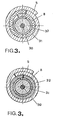
- FIGs 3 show sections of two variants of coaxial cable manufactured by the method according to the invention.
- the central core of this cable consists of a copper conductor 30 on which the dielectric disc 31 is molded.
- a dielectric strip 32 is placed in a manner known per se on said disc 31. It is understood that this strip does not is not essential for carrying out the cable.
- the outer conductor is constituted by the metallic strip 8 of the composite strip 8-5. It is laid overlapping in the variant of FIG. 3A and edge to edge in the variant of FIG. 3B .
- a cable made from a composite tape laid edge to edge has not been shown, although this variant may have an advantage from the point of view of cost price.
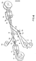
- FIG. 4 schematically represents your production line for a coaxial cable according to FIG. 3A.
- a reel 15 supplies the installation with the metal strip 8, for example made of copper, neces be able to produce the composite tape at the running speed of the central conductor 30 at the outlet of the molding station 11.
- a reel 17 supplies the installation with kraft paper 5 previously coated on the face coming into contact with the metal strip.
- Two rollers 19 and 20 having a suitable speed of rotation ensure the adhesion of the metal strip 8 and of the paper 5 constituting the composite tape 21.
- the former 22 surrounds the core of the coaxial cable of the composite tape 21.
- a heating die 26 ensures sealing the composite tape.
- a pulling member 24 associated with the drum 25 constitutes the reception of the finished cable. We did not specify the enslavements between the various positions of the manufacturing line.
- the applicant also produces a second type of coaxial cable differing from the previous one only in the nature of the external insulation which is a polyester, for example that sold under the name of "Mylar” by Dupont de Nemours.
- the copper strip can be replaced by an aluminum strip of similar thickness and of the same width or a bimetallic strip known per se.
Landscapes
- Engineering & Computer Science (AREA)
- Manufacturing & Machinery (AREA)
- Physics & Mathematics (AREA)
- Electromagnetism (AREA)
- Manufacturing Of Electric Cables (AREA)
- Communication Cables (AREA)
Applications Claiming Priority (2)
| Application Number | Priority Date | Filing Date | Title |
|---|---|---|---|
| FR7906263 | 1979-03-12 | ||
| FR7906263A FR2451619A1 (fr) | 1979-03-12 | 1979-03-12 | Procede de fabrication de paires coaxiales et paires coaxiales ainsi fabriquees |
Publications (2)
| Publication Number | Publication Date |
|---|---|
| EP0015816A1 EP0015816A1 (fr) | 1980-09-17 |
| EP0015816B1 true EP0015816B1 (fr) | 1984-02-08 |
Family
ID=9223018
Family Applications (1)
| Application Number | Title | Priority Date | Filing Date |
|---|---|---|---|
| EP80400256A Expired EP0015816B1 (fr) | 1979-03-12 | 1980-02-22 | Procédé de fabrication d'un câble coaxial |
Country Status (3)
| Country | Link |
|---|---|
| EP (1) | EP0015816B1 (ref) |
| DE (1) | DE3066449D1 (ref) |
| FR (1) | FR2451619A1 (ref) |
Cited By (1)
| Publication number | Priority date | Publication date | Assignee | Title |
|---|---|---|---|---|
| JP2012138468A (ja) * | 2010-12-27 | 2012-07-19 | Yazaki Corp | 導電路シールド構造 |
Families Citing this family (2)
| Publication number | Priority date | Publication date | Assignee | Title |
|---|---|---|---|---|
| EP1135779A1 (en) * | 1998-11-25 | 2001-09-26 | Corning Cable Systems LLC | Method and apparatus for forming a shielded electric cable |
| CN102290153B (zh) * | 2011-06-17 | 2012-10-24 | 雷特威连接系统(苏州工业园区)有限公司 | 微同轴线裹导电布机 |
Citations (1)
| Publication number | Priority date | Publication date | Assignee | Title |
|---|---|---|---|---|
| GB1059438A (en) * | 1965-11-23 | 1967-02-22 | Standard Telephones Cables Ltd | Method of manufacturing an insulated electrical conductor |
Family Cites Families (3)
| Publication number | Priority date | Publication date | Assignee | Title |
|---|---|---|---|---|
| US3399449A (en) * | 1966-06-09 | 1968-09-03 | Bell Telephone Labor Inc | Method of making coaxial cable |
| FR2224844B1 (ref) * | 1973-04-04 | 1976-07-23 | Lignes Telegraph Telephon | |
| FR2325164A1 (fr) * | 1975-09-19 | 1977-04-15 | Fujikura Ltd | Procede de fabrication de cables electriques |
-
1979
- 1979-03-12 FR FR7906263A patent/FR2451619A1/fr active Granted
-
1980
- 1980-02-22 EP EP80400256A patent/EP0015816B1/fr not_active Expired
- 1980-02-22 DE DE8080400256T patent/DE3066449D1/de not_active Expired
Patent Citations (1)
| Publication number | Priority date | Publication date | Assignee | Title |
|---|---|---|---|---|
| GB1059438A (en) * | 1965-11-23 | 1967-02-22 | Standard Telephones Cables Ltd | Method of manufacturing an insulated electrical conductor |
Cited By (1)
| Publication number | Priority date | Publication date | Assignee | Title |
|---|---|---|---|---|
| JP2012138468A (ja) * | 2010-12-27 | 2012-07-19 | Yazaki Corp | 導電路シールド構造 |
Also Published As
| Publication number | Publication date |
|---|---|
| DE3066449D1 (en) | 1984-03-15 |
| FR2451619B1 (ref) | 1982-10-01 |
| FR2451619A1 (fr) | 1980-10-10 |
| EP0015816A1 (fr) | 1980-09-17 |
Similar Documents
| Publication | Publication Date | Title |
|---|---|---|
| EP0964408B1 (fr) | Câble pour la transmission d'informations et son procédé de fabrication | |
| EP1158542B1 (fr) | Cable coaxial flexible et procédé de fabrication de celui-ci | |
| FR2465300A1 (fr) | Cable electrique plat blinde | |
| EP0704735B1 (fr) | Un isolateur électrique équipé de fibres optiques et son procédé de fabrication | |
| CN105706186B (zh) | 制造电力电缆的工艺和相关的电力电缆 | |
| EP0161389B1 (fr) | Câble électrique pour le transport de très fortes intensités sous de faibles tensions et procédés de fabrication d'un tel câble | |
| EP0643399B1 (fr) | Cable de transmission haute fréquence | |
| FR2669143A1 (fr) | Cable electrique a vitesse de propagation elevee. | |
| US3634606A (en) | Outer conductor for coaxial cable | |
| FR2761515A1 (fr) | Cable pour la transmission de donnees et son procede de fabrication | |
| CA2088215C (fr) | Cable electrique haute frequence | |
| EP0778588A1 (fr) | Câble plat à faible marge | |
| EP0015816B1 (fr) | Procédé de fabrication d'un câble coaxial | |
| FR2696580A1 (fr) | Procédé de fabrication de câbles électriques en paires torsadées possédant des conducteurs de longueurs égales, et câbles électriques ainsi obtenus. | |
| BE1013346A6 (fr) | Vitrage avec connexion electrique. | |
| EP0506521A1 (fr) | Vitrage feuilleté chauffant | |
| FR2501407A1 (fr) | Cable mixte associant un cable coaxial ou un guide d'ondes et au moins une fibre optique, et son utilisation | |
| EP1605474B1 (fr) | Cable comportant plusieurs conducteurs isolés enveloppés dans une même gaine et procédé de fabrication d'un tel cable | |
| EP0014621B1 (fr) | Câble coaxial à isolation composite pour télécommunication, procédé de pose de l'isolation extérieure d'un tel câble et dispositif de mise en oeuvre de ce procédé | |
| FR2501382A1 (fr) | Element de cable et cable a fibres optiques, notamment susceptible de resister a des tractions et/ou a des pressions elevees et son procede de fabrication | |
| CH631568A5 (fr) | Cable electrique. | |
| EP1909296B1 (fr) | Procédé de fabrication d'un câble électrique plat à plusieurs conducteurs | |
| FR2723245A1 (fr) | Cable de transport d'energie electrique ou de telecommunication et procede de fabrication d'un tel cable | |
| EP1786001A2 (fr) | Cable électrique avec écran amélioré | |
| EP0707322A1 (fr) | Câble de puissance |
Legal Events
| Date | Code | Title | Description |
|---|---|---|---|
| PUAI | Public reference made under article 153(3) epc to a published international application that has entered the european phase |
Free format text: ORIGINAL CODE: 0009012 |
|
| AK | Designated contracting states |
Designated state(s): BE CH DE GB IT |
|
| 17P | Request for examination filed |
Effective date: 19801010 |
|
| ITF | It: translation for a ep patent filed | ||
| GRAA | (expected) grant |
Free format text: ORIGINAL CODE: 0009210 |
|
| PGFP | Annual fee paid to national office [announced via postgrant information from national office to epo] |
Ref country code: CH Payment date: 19840123 Year of fee payment: 5 |
|
| AK | Designated contracting states |
Designated state(s): BE CH DE GB IT |
|
| REF | Corresponds to: |
Ref document number: 3066449 Country of ref document: DE Date of ref document: 19840315 |
|
| PGFP | Annual fee paid to national office [announced via postgrant information from national office to epo] |
Ref country code: BE Payment date: 19840331 Year of fee payment: 5 |
|
| PLBE | No opposition filed within time limit |
Free format text: ORIGINAL CODE: 0009261 |
|
| STAA | Information on the status of an ep patent application or granted ep patent |
Free format text: STATUS: NO OPPOSITION FILED WITHIN TIME LIMIT |
|
| PGFP | Annual fee paid to national office [announced via postgrant information from national office to epo] |
Ref country code: DE Payment date: 19850114 Year of fee payment: 6 |
|
| 26N | No opposition filed | ||
| PG25 | Lapsed in a contracting state [announced via postgrant information from national office to epo] |
Ref country code: CH Effective date: 19880229 |
|
| BERE | Be: lapsed |
Owner name: LIGNES TELEGRAPHIQUES ET TELEPHONIQUES LTT Effective date: 19880228 |
|
| REG | Reference to a national code |
Ref country code: CH Ref legal event code: PL |
|
| PG25 | Lapsed in a contracting state [announced via postgrant information from national office to epo] |
Ref country code: DE Effective date: 19881101 |
|
| GBPC | Gb: european patent ceased through non-payment of renewal fee | ||
| PG25 | Lapsed in a contracting state [announced via postgrant information from national office to epo] |
Ref country code: GB Free format text: LAPSE BECAUSE OF NON-PAYMENT OF DUE FEES Effective date: 19881118 |
|
| PG25 | Lapsed in a contracting state [announced via postgrant information from national office to epo] |
Ref country code: BE Effective date: 19890228 |