EP0015153B1 - Binding apparatus and method - Google Patents
Binding apparatus and method Download PDFInfo
- Publication number
- EP0015153B1 EP0015153B1 EP80300510A EP80300510A EP0015153B1 EP 0015153 B1 EP0015153 B1 EP 0015153B1 EP 80300510 A EP80300510 A EP 80300510A EP 80300510 A EP80300510 A EP 80300510A EP 0015153 B1 EP0015153 B1 EP 0015153B1
- Authority
- EP
- European Patent Office
- Prior art keywords
- sheets
- group
- heat
- heating
- heating bar
- Prior art date
- Legal status (The legal status is an assumption and is not a legal conclusion. Google has not performed a legal analysis and makes no representation as to the accuracy of the status listed.)
- Expired
Links
- 238000000034 method Methods 0.000 title claims description 26
- 238000010438 heat treatment Methods 0.000 claims description 89
- 239000000463 material Substances 0.000 claims description 20
- 230000000694 effects Effects 0.000 description 8
- 239000000853 adhesive Substances 0.000 description 4
- 230000001070 adhesive effect Effects 0.000 description 4
- 238000004519 manufacturing process Methods 0.000 description 3
- 206010012186 Delayed delivery Diseases 0.000 description 1
- 241000124919 Entodinium simplex Species 0.000 description 1
- 230000002411 adverse Effects 0.000 description 1
- 230000015572 biosynthetic process Effects 0.000 description 1
- 230000008878 coupling Effects 0.000 description 1
- 238000010168 coupling process Methods 0.000 description 1
- 238000005859 coupling reaction Methods 0.000 description 1
- 230000001351 cycling effect Effects 0.000 description 1
- 230000003111 delayed effect Effects 0.000 description 1
- 238000009826 distribution Methods 0.000 description 1
- 239000002245 particle Substances 0.000 description 1
- 239000000126 substance Substances 0.000 description 1
- 229920001169 thermoplastic Polymers 0.000 description 1
- 239000004416 thermosoftening plastic Substances 0.000 description 1
Images


Classifications
-
- B—PERFORMING OPERATIONS; TRANSPORTING
- B42—BOOKBINDING; ALBUMS; FILES; SPECIAL PRINTED MATTER
- B42C—BOOKBINDING
- B42C9/00—Applying glue or adhesive peculiar to bookbinding
-
- B—PERFORMING OPERATIONS; TRANSPORTING
- B29—WORKING OF PLASTICS; WORKING OF SUBSTANCES IN A PLASTIC STATE IN GENERAL
- B29C—SHAPING OR JOINING OF PLASTICS; SHAPING OF MATERIAL IN A PLASTIC STATE, NOT OTHERWISE PROVIDED FOR; AFTER-TREATMENT OF THE SHAPED PRODUCTS, e.g. REPAIRING
- B29C65/00—Joining or sealing of preformed parts, e.g. welding of plastics materials; Apparatus therefor
- B29C65/02—Joining or sealing of preformed parts, e.g. welding of plastics materials; Apparatus therefor by heating, with or without pressure
- B29C65/18—Joining or sealing of preformed parts, e.g. welding of plastics materials; Apparatus therefor by heating, with or without pressure using heated tools
-
- B—PERFORMING OPERATIONS; TRANSPORTING
- B29—WORKING OF PLASTICS; WORKING OF SUBSTANCES IN A PLASTIC STATE IN GENERAL
- B29C—SHAPING OR JOINING OF PLASTICS; SHAPING OF MATERIAL IN A PLASTIC STATE, NOT OTHERWISE PROVIDED FOR; AFTER-TREATMENT OF THE SHAPED PRODUCTS, e.g. REPAIRING
- B29C66/00—General aspects of processes or apparatus for joining preformed parts
- B29C66/01—General aspects dealing with the joint area or with the area to be joined
- B29C66/05—Particular design of joint configurations
- B29C66/10—Particular design of joint configurations particular design of the joint cross-sections
- B29C66/11—Joint cross-sections comprising a single joint-segment, i.e. one of the parts to be joined comprising a single joint-segment in the joint cross-section
- B29C66/112—Single lapped joints
- B29C66/1122—Single lap to lap joints, i.e. overlap joints
-
- B—PERFORMING OPERATIONS; TRANSPORTING
- B29—WORKING OF PLASTICS; WORKING OF SUBSTANCES IN A PLASTIC STATE IN GENERAL
- B29C—SHAPING OR JOINING OF PLASTICS; SHAPING OF MATERIAL IN A PLASTIC STATE, NOT OTHERWISE PROVIDED FOR; AFTER-TREATMENT OF THE SHAPED PRODUCTS, e.g. REPAIRING
- B29C66/00—General aspects of processes or apparatus for joining preformed parts
- B29C66/40—General aspects of joining substantially flat articles, e.g. plates, sheets or web-like materials; Making flat seams in tubular or hollow articles; Joining single elements to substantially flat surfaces
- B29C66/41—Joining substantially flat articles ; Making flat seams in tubular or hollow articles
- B29C66/43—Joining a relatively small portion of the surface of said articles
-
- B—PERFORMING OPERATIONS; TRANSPORTING
- B29—WORKING OF PLASTICS; WORKING OF SUBSTANCES IN A PLASTIC STATE IN GENERAL
- B29C—SHAPING OR JOINING OF PLASTICS; SHAPING OF MATERIAL IN A PLASTIC STATE, NOT OTHERWISE PROVIDED FOR; AFTER-TREATMENT OF THE SHAPED PRODUCTS, e.g. REPAIRING
- B29C66/00—General aspects of processes or apparatus for joining preformed parts
- B29C66/80—General aspects of machine operations or constructions and parts thereof
- B29C66/81—General aspects of the pressing elements, i.e. the elements applying pressure on the parts to be joined in the area to be joined, e.g. the welding jaws or clamps
- B29C66/814—General aspects of the pressing elements, i.e. the elements applying pressure on the parts to be joined in the area to be joined, e.g. the welding jaws or clamps characterised by the design of the pressing elements, e.g. of the welding jaws or clamps
- B29C66/8141—General aspects of the pressing elements, i.e. the elements applying pressure on the parts to be joined in the area to be joined, e.g. the welding jaws or clamps characterised by the design of the pressing elements, e.g. of the welding jaws or clamps characterised by the surface geometry of the part of the pressing elements, e.g. welding jaws or clamps, coming into contact with the parts to be joined
- B29C66/81433—General aspects of the pressing elements, i.e. the elements applying pressure on the parts to be joined in the area to be joined, e.g. the welding jaws or clamps characterised by the design of the pressing elements, e.g. of the welding jaws or clamps characterised by the surface geometry of the part of the pressing elements, e.g. welding jaws or clamps, coming into contact with the parts to be joined being toothed, i.e. comprising several teeth or pins, or being patterned
-
- B—PERFORMING OPERATIONS; TRANSPORTING
- B29—WORKING OF PLASTICS; WORKING OF SUBSTANCES IN A PLASTIC STATE IN GENERAL
- B29C—SHAPING OR JOINING OF PLASTICS; SHAPING OF MATERIAL IN A PLASTIC STATE, NOT OTHERWISE PROVIDED FOR; AFTER-TREATMENT OF THE SHAPED PRODUCTS, e.g. REPAIRING
- B29C66/00—General aspects of processes or apparatus for joining preformed parts
- B29C66/80—General aspects of machine operations or constructions and parts thereof
- B29C66/82—Pressure application arrangements, e.g. transmission or actuating mechanisms for joining tools or clamps
- B29C66/824—Actuating mechanisms
- B29C66/8242—Pneumatic or hydraulic drives
-
- B—PERFORMING OPERATIONS; TRANSPORTING
- B29—WORKING OF PLASTICS; WORKING OF SUBSTANCES IN A PLASTIC STATE IN GENERAL
- B29C—SHAPING OR JOINING OF PLASTICS; SHAPING OF MATERIAL IN A PLASTIC STATE, NOT OTHERWISE PROVIDED FOR; AFTER-TREATMENT OF THE SHAPED PRODUCTS, e.g. REPAIRING
- B29C66/00—General aspects of processes or apparatus for joining preformed parts
- B29C66/80—General aspects of machine operations or constructions and parts thereof
- B29C66/83—General aspects of machine operations or constructions and parts thereof characterised by the movement of the joining or pressing tools
- B29C66/832—Reciprocating joining or pressing tools
-
- B—PERFORMING OPERATIONS; TRANSPORTING
- B29—WORKING OF PLASTICS; WORKING OF SUBSTANCES IN A PLASTIC STATE IN GENERAL
- B29C—SHAPING OR JOINING OF PLASTICS; SHAPING OF MATERIAL IN A PLASTIC STATE, NOT OTHERWISE PROVIDED FOR; AFTER-TREATMENT OF THE SHAPED PRODUCTS, e.g. REPAIRING
- B29C65/00—Joining or sealing of preformed parts, e.g. welding of plastics materials; Apparatus therefor
- B29C65/02—Joining or sealing of preformed parts, e.g. welding of plastics materials; Apparatus therefor by heating, with or without pressure
- B29C65/18—Joining or sealing of preformed parts, e.g. welding of plastics materials; Apparatus therefor by heating, with or without pressure using heated tools
- B29C65/24—Joining or sealing of preformed parts, e.g. welding of plastics materials; Apparatus therefor by heating, with or without pressure using heated tools characterised by the means for heating the tool
- B29C65/30—Electrical means
-
- G—PHYSICS
- G03—PHOTOGRAPHY; CINEMATOGRAPHY; ANALOGOUS TECHNIQUES USING WAVES OTHER THAN OPTICAL WAVES; ELECTROGRAPHY; HOLOGRAPHY
- G03G—ELECTROGRAPHY; ELECTROPHOTOGRAPHY; MAGNETOGRAPHY
- G03G2215/00—Apparatus for electrophotographic processes
- G03G2215/00362—Apparatus for electrophotographic processes relating to the copy medium handling
- G03G2215/00789—Adding properties or qualities to the copy medium
- G03G2215/00822—Binder, e.g. glueing device
- G03G2215/00835—Toner binding
-
- Y—GENERAL TAGGING OF NEW TECHNOLOGICAL DEVELOPMENTS; GENERAL TAGGING OF CROSS-SECTIONAL TECHNOLOGIES SPANNING OVER SEVERAL SECTIONS OF THE IPC; TECHNICAL SUBJECTS COVERED BY FORMER USPC CROSS-REFERENCE ART COLLECTIONS [XRACs] AND DIGESTS
- Y10—TECHNICAL SUBJECTS COVERED BY FORMER USPC
- Y10S—TECHNICAL SUBJECTS COVERED BY FORMER USPC CROSS-REFERENCE ART COLLECTIONS [XRACs] AND DIGESTS
- Y10S412/00—Bookbinding: process and apparatus
- Y10S412/902—Heating and pressing
Definitions
- the present invention relates to binding apparatus and method for securing together a plurality of sheets having a heat-sealable material between adjacent surfaces of the sheets.
- U.S. Patent Numbers 3,793,016 and 3,794,550 disclose xerographic copiers and processes wherein a pattern of toner is applied along an edge portion of each of a plurality of copy sheets and fused to the copy sheets as the copies are made. Then the sheets are arranged so that the pattern of toner is overlapping on adjacent sheets, and the toner is heated to re-fuse the toner, thereby to bind the adjacent sheets together.
- These patents disclose both on-line binding apparatus and off-line binding apparatus wherein re-fusing of toner secures the sheets together.
- Another disadvantage of the binding apparatus and method disclosed in the aforementioned patents is that all the toner that is to be re-fused to effect binding is heated simultaneously. Thus all of it is re-fused each time the toner heaters effect binding. When additional sheets are to be added to a bound stack and the sheets are reheated again, some of the toner must be re-fused a second time in order to adhere the new sheets to the stack. Such re- fusing adversely affects the bonding strength between those sheets that are bound by the toner that was re-fused twice.
- patterned heating shoes or bars for various purposes. Such patterned heating bars are disclosed, for example, in U.S. Patent Numbers 3258385, 3560290 and 4070513. Patterned heating bars such as disclosed in those patents are used for applying a pattern of heat to seal film or the like only once, that is, the patterned heating bar is not moved into engagement with the joint to be sealed more than once.
- a method for securing together a plurality of sheets having a heat-sealable material between adjacent surfaces of the sheets comprising the step of supporting a group of unattached sheets in overlapping relation with the heat-sealable material located between adjacent sheets and the step of selectively heating a first portion of the heat-sealable material, characterised in that the binding method further comprises the step of placing over the group of sheets a second group of unattached sheets with the heat-sealable material located between adjacent sheets of the second group and between the second group and one sheet of the first- mentioned group, and the step of selectively heating a first portion of the heat-sealable material between sheets of the second group and also a portion of the heat-sealable material between the second group and one sheet of the first group aligned with the first portion of the heat-sealable material of the second group, the first portion of the heat-sealable material of the second group of sheets being offset from the first portion of the heat
- binding apparatus for carrying out the method set out in the immediately preceding paragraph comprising a supporting means for supporting a group of unattached sheets in overlapping relation, and a heating bar for selectively applying heat, the heating bar being movable toward and away from the supporting means, characterised in that the heating bar is additionally movable transversely of the supporting means between positions of heat transferring engagement with any sheets supported thereby, and by means for placing over the said group of sheets a second group of unattached sheets.
- finishers and finishing methods are well known, the present description will be directed in particular to those elements or steps forming part of the binding apparatus or method of the present invention. Elements of the apparatus or method steps not specifically described can be selected from those known in the art.
- the binding apparatus generally designated 34 of the present invention is shown incorporated in a finisher generally designated 10 which receives copy sheets 12 seriatim from a copier/duplicator 14.
- the copy sheets 12 are delivered to the finisher 10 through aligned openings or guide slots 16 and 18 in the copier/duplicator 14 and the finisher 10, respectively.
- the copied information is on the lower face of the sheets 12 as the sheets 12 travel through the slots 16, 18.
- the sheets 12 have information copied on both sides thereof (i.e. duplex copies), ordinarily the odd numbered pages face downwardly in the slots 16, 18.
- the sheets 12 are advanced toward the binding apparatus 34 by a plurality of pairs of driven rollers 20 and idler rollers 22.
- the sheets 12 then engage a curved guide 24 which initially deflects the sheets 12 into the nip between a drive roller 26 and an idler roller 28.
- the guide 24 and rollers 26, 28 turn the sheet 12 over so that the side of the sheet 12 which was facing downwardly in the guide slots 16 and 18 faces generally upwardly as it leaves the roller 26 and the guide 24.
- the guide 24 directs the sheet into the nip of a pair of rollers 30 and 32 which drive the sheets into the binding apparatus 34.
- the booklet 48 is gripped by a clamp 36 operated by a pneumatic cylinder 38.
- the clamp 36 and the cylinder 38 are supported on an arm 40 which is movable about a pivot 42 by another pneumatic cylinder 44 to bring the completed booklet 48 into a position over a tray 46 where the booklet 48 is released.
- the tray 46 supports a plurality of completed booklets 48, and the tray 46 is mounted on a lift for movement in an up and down direction as indicated by arrows 50 so that an entire stack of the booklets 48 may be accumulated on the tray 46 for removal.
- the apparatus shown in Figure 1 is similar to that embodied in an earlier EKTAPRINT (a trademark) copier/duplicator and finisher manufactured by the applicant of the present application.
- the earier EKTAPRINT (a trademark) finisher has stiching apparatus for stapling stacks of sheets together in booklet form.
- the binding apparatus 34 of the present invention may be used in lieu of such stitching apparatus or in addition to that apparatus so that the user of the equipment has a choice of either stapling or binding by re-fusing of toner as disclosed hereinafter.
- the adhesive material used for binding sheets together may be any suitable heat sealable adhesive, such as a thermoplastic adhesive, and preferably comprises a cross-linked toner composition.
- a cross-linked toner is disclosed in U.S. Patent No. 3,938,992.
- Sheets 12 furnished to the binding apparatus 34 also are provided with a pattern of toner located in an area where it can be used in binding adjacent sheets together.
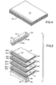
- the pattern and area comprise a stripe 52 of toner located adjacent and parallel to a side edge of the sheets 12 as illustrated in Figure 3.
- the sheets 12 are delivered to the binding apparatus 34 and received in a tray 54 which receives the sheets 12 and holds the stack of the sheets 12 with the toner stripes 52 of the sheets 12 aligned throughout the stack of sheets 12 in the tray 54.
- a heating shoe 56 Located beneath the tray 54 and in alignment with the portion of the sheets 12 having the toner stripe 52 thereon, is a heating shoe 56 that has a smooth, bar-like surface 58. As explained later, heat is transferred from the heating shoe 56 to the toner stripe 52 on sheets 12. A heating element 60 in the heating shoe 56 transfers heat to the surface 58.
- the surface 58 is located immediately beneath the tray 54, as shown in Figure 1, and is aligned with the toner stripe 52 on each of the sheets 12.
- the heating shoe 56 may extend along the upper edge of the tray 54 or it may project through a slot in the tray 54.
- the heating shoe 56 is stationary and forms a back-up member for a movable heating bar 62.
- the heating bar 62 preferably has an elongate surface 64 with a pattern thereon comprising raised portions 66 and recessed portions 68. Heat is transmitted from the raised portions 66 to the toner stripes 52.
- the recessed portions 68 are located below the level of the raised portions 66 on surface 64, and the area of the raised portions 66 is substantially equal to the area of the recessed portions 68. Also, as illustrated in Figure 3, the raised portions 66 and recessed portions 68 are alternately arranged along the surface 64 in a repeating pattern that extends the entire length of the heating bar 62.
- the particular pattern shown in Figure 3 comprises three rows of elongate recessed portions 68, each recess in a row being spaced from the adjacent recesses in that row by a raised portion that extends a distance equal to the length of one of the recessed portions 68.
- Alternate rows of the recessed portions 68 are offset or staggered so that the first and third rows of the recessed portions 68 are aligned and the row therebetween is offset from the first and third rows by the length 6f one of the recessed portions 68.
- the first and third rows are separated by a distance equal to the width of one of the recessed portions 68.
- the surface 64 may be about 1/4 inch (6.4 millimetres) wide, and each of the recessed portions 68 may be on the order of 1/4 inch (6.4 millimetres) in length.
- the raised portions 66 of the heating bar 62 are heated by means of a heating element 70 located in the heating bar 62.
- the heating elements 60 and 70 may be of any suitable type, such as electrical resistance heating elements.
- FIG. 2 illustrates the binding apparatus 34 of the present invention.
- the binding apparatus 34 comprises means for mounting the heating shoe 56 and the heating bar 62, and for moving the heating bar 62 relative to the heating shoe 56.
- the finisher 10 has a pair of spaced frame members 74 and 76.
- a plate 78 has end flanges that are secured to the frame members 74 and 76.
- the heating shoe 56 is rigidly secured to the plate 78, thereby fixedly mounting the heating shoe 56 in position.
- a pneumatic cylinder 80 is secured to the frame member 74, and a similar cylinder 82 is secured to the frame member 76.
- the cylinders 80 and 82 have rods 84 and 86, respectively, which are extended and retracted in a conventional manner.
- the rods 84 and 86 are connected to the ends of a plate 88.
- a plate 90 is secured to the plate 88 by bolts 92 which extend through elongate slots 94 in the plate 90 and into the plate 88, thereby providing for lateral (left or right) movement of the plate 90 relative to the plate 88.
- the heating bar 62 is fixed to the plate 90 and located with respect to the heating shoe 56 so that extension and retraction of the rods 84 and 86 upon operation of the cylinders 80 and 82 effects movement of the heating bar 62 toward and away from the heating shoe 56.
- Lateral movement of the plate 90, and thus of the heating bar 62, is achieved by a third pneumatic cylinder 96 which has an extensible rod 98 connected by means of a coupling 100 to the plate 90.
- the cylinder 96 is mounted on the plate 88 and the axis of the cylinder 96 and the rod 98 are aligned with the slots 94 so that extension and retraction of the rod 98 effects lateral movement of the plate 90 with respect to the plate 88.
- the position of the heating bar 62 may be shifted longitudinally, that is, in the direction of the rows of the raised portions 66 and the recessed portions 68 forming the pattern on the surface 64 of the heating bar 62.
- the heating bar 62 travels in a generally U-shaped path as it repetitively moves into and out of engagement with the sheets 12 between the heating bar 62 and the heating shoe 56.
- the binding apparatus 34 is controlled by suitable means (not shown), such as from the computer that also controls operation of the associated copier/duplicator 14.
- suitable means such as from the computer that also controls operation of the associated copier/duplicator 14.
- the following description initially details the on-line binding method of the present invention; that is, the sheets 12 delivered to the tray 54 are directly from the copier/duplicator 14 and at the same rate they are produced by the copier/duplicator 14.
- the binding apparatus 34 is required to bind sheets 12 together at the same rate as they are produced by operation of the copier/duplicator 14.
- the binding apparatus 34 preferably cycles to bind the sheets 12 together after each group of a few sheets 12 is fed to the binding apparatus 34, and additional sheets 12 are bound to each other, and to previously bound sheets 12 after each group of a few sheets 12 is received from the copier/duplicator 14.
- the binding apparatus 34 cycling after delivery of each group of three sheets 12, and describes the formation of a booklet 48 comprising four groups of the sheets 12 as shown at G1-G4 in Figure 3. Very little time is required for binding sheets 12 together in small groups, such as groups of three sheets 12, because the length of time required for the heat to penetrate the sheets 12 to re-fuse the toner to effect bonding is directly related to the number and thickness of the stack of sheets 12.
- the heating elements 60 and 70 are turned on to heat the surface 58 of the heating shoe 56 and the surface 64 of the heating bar 62.
- the sheets 12 are delivered to the tray 54 seriatim from the copier/duplicator 14 through the guide slots 16, 18 and through the nip formed by the rollers 30 and 32.
- the cylinders 80 and 82 are activated to retract the associated rods 84 and 86, respectively, thereby moving the heating bar 62 toward the heating shoe 56 until the sheets 12 therebetween are compressed. Heat is transferred from the heating bar 62 and the heating shoe 56 through the toner stripes 52 located therebetween.
- Heat is transferred through the surface 58 of the heating shoe 56 along the full length and width of the toner stripe 52.
- heat is transferred from the heating bar 62 primarily through the raised portions 66 of the surface 64 so that re- fusing of the toner stripe 52 on at least the top sheet of the first group G 1 of three sheets 12 is primarily in the area immediately beneath the raised portions 66, such re-fused portions being designated 66a in Figure 3.
- the toner portion 66a on the uppermost sheet has been re-fused once whereas the remaining toner portion 68a, which lies beneath the recessed portions 68, remains unre-fused.
- the cylinders 80, 82 are operated to separate the heating bar 62 from the first group G1 of sheets 12, an additional group G2 of three sheets 12 is delivered to the tray 54 on top of the first group G1 of sheets 12.
- the cylinder 96 is operated to move the rod 98, thereby shifting the plate 90 and the heating bar 62 by a distance equal to the spacing between two longitudinally adjacent recessed portions 68 in the pattern on the surface 64.
- the cylinders 80 and 82 are again operated to bring the heating bar 62 toward the heating shoe 56 to compress the second group G2 of three sheets 12 against the first group G1 of three sheets 12.
- the cylinders 80 and 82 are again operated to separate the heating bar 62 from the stack of sheets 12, the cylinder 96 is operated to shift the heating bar 62 laterally and, after another group G3 of three sheets 12 have been delivered to the tray 54 on top of the second group G2 of three sheets 12, the cylinders 80 and 82 again drive the heating bar 62 toward the heating shoe 56 so that the heating bar 62 engages the top one of the sheets 12 in the group G3 of sheets 12.
- the pattern on the surface 64 of the heating bar 62 is located in the same relative position as it was when it engaged the first group G of three sheets 12 so that it again forms a pattern of re-fused and unre-fused toner portions designated 66c and 68c, respectively.
- the method of the present invention also may be practised on an off-line basis by simply placing stacks of sheets 12 to be bonded together in the tray 54 and energising the cylinders 80 and 82 to bring the heating bar 62 toward the heating shoe 56 where it remains in place until sufficient heat is transferred through an entire stack of sheets 12 in order to bind all the sheets 12 together.
- booklets of about twenty-five sheets 12 may be adhered together in a single cycle of operation.
- the time required for transfer of heat through a relatively thick booklet of this type is more than is normally available for on-line operation with high speed copier/duplicators.
- the operating temperatures, pressures, time cycles and other parameters used depend on a number of factors, including the chemical composition of the particular toner or other adhesive used, the number of sheets in a group of sheets being bound together by the on-line method or the total number of sheets being bound together by the off-line method, and the thickness and type of paper used.
- the heating bars 60 and 70 may be heated to approximately 350 to 370°F (177 to 188°C) with the preferred temperature being 360°F (182°C).
- the air cylinders 80 and 82 receive air under sufficient pressure to exert a pressure of about 40 psi (2.8 kg/cm 2 ) against the groups of sheets Gl-G4.
- the total cycle time is approximately 1.1 second plus or minus 0.2 second.
- EKTAPRINT a trademark copier/ duplicator
- longer cycle times may be used when the copier production rate is lower and shorter cycle times are required for higher production rates.
- the preferred time cycle for a stack of 10 sheets of paper in a group is fifteen seconds. Twenty-five sheets of paper will require approximately 30 seconds of time, and fifty sheets of paper will require approximately 90 seconds of time.
- These cycle times for the off-line mode of operation are the times required for binding all sheets together in a single bonding step in which the heating bar 62 and the heating shoe 56 remain in contact with the stack of sheets until all of the sheets are bound together.
- the toner stripes 52 have been shown on the upper surface only of each sheet 12. However, if desired the toner stripe may alternatively be applied to the lower surface only or to both surfaces of a copy sheet. When duplex copies are being received from the copier/duplicator 14, toner stripes 52 may be applied to both surfaces or alternate sheets. When the upper and/or lower sheet of a booklet is a cover sheet that has not received a toner image in the copier/duplicator 14, the cover sheets may be adhered to the copy sheets with stripes of toner on those copy sheets adjacent to the cover sheets.
- the binding apparatus 34 Whilst the binding apparatus 34 is engaged with sheets 12 to effect re-fusing of toner, the delivery of subsequent sheets 12 can be delayed by the rollers 20 and 22 of the finisher 10. Apparatus for effecting delayed delivery of sheets 12 is embodied in the previously- mentioned EKTAPRINT (a trademark) finisher.
- the binding method of the present invention has been described in connection with the operation of the binding apparatus 34; however, the method steps may be carried out with other types of apparatus.
Landscapes
- Engineering & Computer Science (AREA)
- Mechanical Engineering (AREA)
- Physics & Mathematics (AREA)
- Fluid Mechanics (AREA)
- Folding Of Thin Sheet-Like Materials, Special Discharging Devices, And Others (AREA)
- Adhesives Or Adhesive Processes (AREA)
Applications Claiming Priority (2)
| Application Number | Priority Date | Filing Date | Title |
|---|---|---|---|
| US06/013,869 US4343673A (en) | 1979-02-22 | 1979-02-22 | Binding apparatus and method |
| US13869 | 1979-02-22 |
Publications (2)
| Publication Number | Publication Date |
|---|---|
| EP0015153A1 EP0015153A1 (en) | 1980-09-03 |
| EP0015153B1 true EP0015153B1 (en) | 1983-06-22 |
Family
ID=21762216
Family Applications (1)
| Application Number | Title | Priority Date | Filing Date |
|---|---|---|---|
| EP80300510A Expired EP0015153B1 (en) | 1979-02-22 | 1980-02-21 | Binding apparatus and method |
Country Status (4)
| Country | Link |
|---|---|
| US (1) | US4343673A (mo) |
| EP (1) | EP0015153B1 (mo) |
| JP (1) | JPS55121095A (mo) |
| DE (1) | DE3063809D1 (mo) |
Cited By (1)
| Publication number | Priority date | Publication date | Assignee | Title |
|---|---|---|---|---|
| EP4523921A1 (en) * | 2023-09-14 | 2025-03-19 | Canon Kabushiki Kaisha | Image forming system |
Families Citing this family (26)
| Publication number | Priority date | Publication date | Assignee | Title |
|---|---|---|---|---|
| US4473425A (en) * | 1982-05-24 | 1984-09-25 | Eastman Kodak Company | Binding apparatus and method |
| US4540458A (en) * | 1982-05-24 | 1985-09-10 | Eastman Kodak Company | Adhesive binding method for seriatim fed sheets |
| US4525116A (en) * | 1982-12-27 | 1985-06-25 | The Holmberg Company | Prefabricated bindable sheet and binding method and apparatus |
| JPS60168415U (ja) * | 1984-04-16 | 1985-11-08 | 株式会社日立ホームテック | ジユ−サ− |
| US4586640A (en) * | 1984-08-21 | 1986-05-06 | Xerox Corporation | Printing machine finishing station |
| US4775572A (en) * | 1987-10-13 | 1988-10-04 | Xerox Corporation | Embossed binding tape |
| FR2622147B1 (fr) * | 1987-10-21 | 1992-12-11 | Lavigne Calendriers Jean | Procede de reunion en blocs de feuillets imprimes, notamment pour constituer des calendriers |
| US4958974A (en) * | 1989-08-07 | 1990-09-25 | Xerox Corporation | Damped binding apparatus |
| US5582570A (en) * | 1991-05-20 | 1996-12-10 | Roll Systems, Inc. | Method and apparatus for binding sheets using a printing substance |
| US5632853A (en) * | 1995-04-26 | 1997-05-27 | International Binding Corporation | Adhesive cartridge for a desktop book binder |
| US5806842A (en) * | 1996-06-28 | 1998-09-15 | Bdt Products, Inc. | Output paper sheet finishing module and method of using same |
| US6330999B2 (en) | 1998-05-14 | 2001-12-18 | Graoco (Japan) Ltd | Set binding, stapling and stacking apparatus |
| US6760119B1 (en) * | 1999-05-25 | 2004-07-06 | Silverbrook Research Pty Ltd | Relay device |
| US6644642B1 (en) * | 1999-05-25 | 2003-11-11 | Silverbrook Research Pty Ltd | Printed media parallel binder |
| US6394728B1 (en) | 1999-05-26 | 2002-05-28 | Hewlett-Packard Company | Binding sheet media using imaging material |
| EP1116600A3 (en) | 2000-01-11 | 2002-03-06 | Hewlett-Packard Company, A Delaware Corporation | Apparatus and method for binding sheet media |
| AUPR157400A0 (en) * | 2000-11-20 | 2000-12-14 | Silverbrook Research Pty. Ltd. | An apparatus and method (bin01) |
| US6601840B2 (en) | 2001-08-09 | 2003-08-05 | Hewlett-Packard Development Company, L.P. | Post print finishing device with imaging material binder |
| US6688719B2 (en) * | 2002-04-12 | 2004-02-10 | Silverbrook Research Pty Ltd | Thermoelastic inkjet actuator with heat conductive pathways |
| JP4544409B2 (ja) * | 2004-08-12 | 2010-09-15 | マックス株式会社 | 製本装置 |
| US20060073299A1 (en) * | 2004-10-04 | 2006-04-06 | Edward Killey | Method for forming a metallic appearance on the sides of memo pads |
| US8313883B2 (en) | 2010-05-24 | 2012-11-20 | Eastman Kodak Company | Electrophotographic print binding method |
| US20110286779A1 (en) | 2010-05-24 | 2011-11-24 | Kwarta Brian J | Electrophotographic print binding method and system |
| US8548371B2 (en) | 2010-05-24 | 2013-10-01 | Eastman Kodak Company | Electrophotographic print binding system |
| US8701733B2 (en) | 2011-01-07 | 2014-04-22 | Nike, Inc. | Shoe customization system having interchangeable platens |
| JP2014198627A (ja) * | 2013-02-14 | 2014-10-23 | 株式会社リコー | 綴じ処理装置および画像形成システム |
Family Cites Families (6)
| Publication number | Priority date | Publication date | Assignee | Title |
|---|---|---|---|---|
| NL278659A (mo) * | 1961-11-07 | 1900-01-01 | ||
| US3560290A (en) * | 1969-02-14 | 1971-02-02 | Mortimer S Sendor | Bookbinding with welded pages |
| US3933571A (en) * | 1971-09-23 | 1976-01-20 | Donray Products Company | Sealing apparatus utilizing adjustable jaw portions |
| US3794550A (en) * | 1972-08-25 | 1974-02-26 | Standard Oil Co | Sheet binding |
| US3793016A (en) * | 1972-10-19 | 1974-02-19 | Xerox Corp | Electrophotographic sheet binding process |
| US4063983A (en) * | 1975-10-20 | 1977-12-20 | Bergstein Packaging Trust | Orbital heat sealing apparatus and method |
-
1979
- 1979-02-22 US US06/013,869 patent/US4343673A/en not_active Expired - Lifetime
-
1980
- 1980-02-21 DE DE8080300510T patent/DE3063809D1/de not_active Expired
- 1980-02-21 EP EP80300510A patent/EP0015153B1/en not_active Expired
- 1980-02-22 JP JP2150580A patent/JPS55121095A/ja active Granted
Cited By (1)
| Publication number | Priority date | Publication date | Assignee | Title |
|---|---|---|---|---|
| EP4523921A1 (en) * | 2023-09-14 | 2025-03-19 | Canon Kabushiki Kaisha | Image forming system |
Also Published As
| Publication number | Publication date |
|---|---|
| EP0015153A1 (en) | 1980-09-03 |
| DE3063809D1 (en) | 1983-07-28 |
| JPS5754319B2 (mo) | 1982-11-17 |
| JPS55121095A (en) | 1980-09-17 |
| US4343673A (en) | 1982-08-10 |
Similar Documents
| Publication | Publication Date | Title |
|---|---|---|
| EP0015153B1 (en) | Binding apparatus and method | |
| US4398986A (en) | Binding method | |
| US7673862B2 (en) | Sheet processor and image-forming apparatus | |
| US5320336A (en) | Sheet stacking device with vertically movable tray | |
| US20060263174A1 (en) | Sheet-bundle spine treatment apparatus, sheet-bundle treatment apparatus, and image-forming apparatus | |
| EP1000894A2 (en) | Folding device for an image forming apparatus | |
| US4511297A (en) | Apparatus and method for offsetting and delaying delivery of sheets in an adhesive binder | |
| US6929256B2 (en) | Post processing device with saddle stitching | |
| US7413176B2 (en) | Sheet finisher | |
| US8308412B2 (en) | Adhesive applicator and bookmaking apparatus using the same | |
| US5649695A (en) | Continuous sheet stacker and finisher | |
| US5240362A (en) | Image forming apparatus with book bind device | |
| JP4720620B2 (ja) | カール補正装置及びこれを備えた画像形成装置 | |
| EP0590359B1 (en) | Machine for folding sheets of paper | |
| JP2009018494A (ja) | 製本処理方法及び製本装置並びに画像形成システム | |
| EP0245234B1 (en) | Apparatus for glueing together material layers | |
| US6139012A (en) | Image forming unit system | |
| EP1208999B1 (en) | System for connecting document sheets | |
| JP2010143196A (ja) | 製本装置及び製本システム | |
| JP2009018492A (ja) | 製本装置及び画像形成システム | |
| JP2004205772A (ja) | 用紙後処理装置を備えた画像形成システム | |
| JP2002326473A (ja) | 後処理装置及び画像形成装置 | |
| JP2018144317A (ja) | 製本装置 | |
| JP2954975B2 (ja) | シートの運搬及び位置決めのための装置 | |
| JP2010082790A (ja) | シート束断裁装置及びこれを備えた製本装置並びに画像形成装置 |
Legal Events
| Date | Code | Title | Description |
|---|---|---|---|
| PUAI | Public reference made under article 153(3) epc to a published international application that has entered the european phase |
Free format text: ORIGINAL CODE: 0009012 |
|
| AK | Designated contracting states |
Designated state(s): DE FR GB |
|
| DET | De: translation of patent claims | ||
| 17P | Request for examination filed |
Effective date: 19810122 |
|
| GRAA | (expected) grant |
Free format text: ORIGINAL CODE: 0009210 |
|
| AK | Designated contracting states |
Designated state(s): DE FR GB |
|
| REF | Corresponds to: |
Ref document number: 3063809 Country of ref document: DE Date of ref document: 19830728 |
|
| EL | Fr: translation of claims filed | ||
| KL | Correction list |
Free format text: 83/04 |
|
| PLBE | No opposition filed within time limit |
Free format text: ORIGINAL CODE: 0009261 |
|
| STAA | Information on the status of an ep patent application or granted ep patent |
Free format text: STATUS: NO OPPOSITION FILED WITHIN TIME LIMIT |
|
| 26N | No opposition filed | ||
| PGFP | Annual fee paid to national office [announced via postgrant information from national office to epo] |
Ref country code: DE Payment date: 19920318 Year of fee payment: 13 |
|
| PG25 | Lapsed in a contracting state [announced via postgrant information from national office to epo] |
Ref country code: DE Effective date: 19931103 |
|
| PGFP | Annual fee paid to national office [announced via postgrant information from national office to epo] |
Ref country code: GB Payment date: 19970106 Year of fee payment: 18 |
|
| PGFP | Annual fee paid to national office [announced via postgrant information from national office to epo] |
Ref country code: FR Payment date: 19970211 Year of fee payment: 18 |
|
| PG25 | Lapsed in a contracting state [announced via postgrant information from national office to epo] |
Ref country code: GB Free format text: LAPSE BECAUSE OF NON-PAYMENT OF DUE FEES Effective date: 19980221 |
|
| PG25 | Lapsed in a contracting state [announced via postgrant information from national office to epo] |
Ref country code: FR Free format text: THE PATENT HAS BEEN ANNULLED BY A DECISION OF A NATIONAL AUTHORITY Effective date: 19980228 |
|
| GBPC | Gb: european patent ceased through non-payment of renewal fee |
Effective date: 19980221 |
|
| REG | Reference to a national code |
Ref country code: FR Ref legal event code: ST |