EP0014693A1 - Verbesserter Ultraschall-Wandler - Google Patents
Verbesserter Ultraschall-Wandler Download PDFInfo
- Publication number
- EP0014693A1 EP0014693A1 EP80850016A EP80850016A EP0014693A1 EP 0014693 A1 EP0014693 A1 EP 0014693A1 EP 80850016 A EP80850016 A EP 80850016A EP 80850016 A EP80850016 A EP 80850016A EP 0014693 A1 EP0014693 A1 EP 0014693A1
- Authority
- EP
- European Patent Office
- Prior art keywords
- reflective layer
- ultrasonic transducer
- improved ultrasonic
- piezoelectric element
- thickness
- Prior art date
- Legal status (The legal status is an assumption and is not a legal conclusion. Google has not performed a legal analysis and makes no representation as to the accuracy of the status listed.)
- Granted
Links
- 239000002033 PVDF binder Substances 0.000 claims abstract description 14
- 229920002981 polyvinylidene fluoride Polymers 0.000 claims abstract description 14
- 239000000758 substrate Substances 0.000 claims description 24
- 229920000642 polymer Polymers 0.000 claims description 12
- 239000000463 material Substances 0.000 claims description 10
- 229910052802 copper Inorganic materials 0.000 claims description 7
- 239000002184 metal Substances 0.000 claims description 7
- 229910052751 metal Inorganic materials 0.000 claims description 7
- 229920006254 polymer film Polymers 0.000 claims description 6
- 229910052737 gold Inorganic materials 0.000 claims description 4
- 239000000203 mixture Substances 0.000 claims description 4
- -1 trifluoroethylene, hexafluoropropylene Chemical group 0.000 claims description 4
- 239000000919 ceramic Substances 0.000 claims description 3
- 229910052804 chromium Inorganic materials 0.000 claims description 3
- 229920001577 copolymer Polymers 0.000 claims description 3
- 229910052709 silver Inorganic materials 0.000 claims description 3
- BQCIDUSAKPWEOX-UHFFFAOYSA-N 1,1-Difluoroethene Chemical compound FC(F)=C BQCIDUSAKPWEOX-UHFFFAOYSA-N 0.000 claims description 2
- OEPOKWHJYJXUGD-UHFFFAOYSA-N 2-(3-phenylmethoxyphenyl)-1,3-thiazole-4-carbaldehyde Chemical compound O=CC1=CSC(C=2C=C(OCC=3C=CC=CC=3)C=CC=2)=N1 OEPOKWHJYJXUGD-UHFFFAOYSA-N 0.000 claims description 2
- 150000002739 metals Chemical class 0.000 claims description 2
- 239000002861 polymer material Substances 0.000 claims description 2
- BFKJFAAPBSQJPD-UHFFFAOYSA-N tetrafluoroethene Chemical group FC(F)=C(F)F BFKJFAAPBSQJPD-UHFFFAOYSA-N 0.000 claims description 2
- 239000010410 layer Substances 0.000 claims 9
- 229920002319 Poly(methyl acrylate) Polymers 0.000 claims 1
- 239000000956 alloy Substances 0.000 claims 1
- 229910045601 alloy Inorganic materials 0.000 claims 1
- 239000000470 constituent Substances 0.000 claims 1
- 229910052745 lead Inorganic materials 0.000 claims 1
- 229910052759 nickel Inorganic materials 0.000 claims 1
- 239000011241 protective layer Substances 0.000 claims 1
- 229910052718 tin Inorganic materials 0.000 claims 1
- 229910052721 tungsten Inorganic materials 0.000 claims 1
- 238000005530 etching Methods 0.000 abstract description 5
- 230000009467 reduction Effects 0.000 abstract description 2
- 239000010949 copper Substances 0.000 description 12
- 229920003229 poly(methyl methacrylate) Polymers 0.000 description 6
- 239000004926 polymethyl methacrylate Substances 0.000 description 6
- 230000005540 biological transmission Effects 0.000 description 5
- RYGMFSIKBFXOCR-UHFFFAOYSA-N Copper Chemical compound [Cu] RYGMFSIKBFXOCR-UHFFFAOYSA-N 0.000 description 4
- 230000008901 benefit Effects 0.000 description 4
- 238000004519 manufacturing process Methods 0.000 description 4
- XLYOFNOQVPJJNP-UHFFFAOYSA-N water Substances O XLYOFNOQVPJJNP-UHFFFAOYSA-N 0.000 description 4
- 230000008878 coupling Effects 0.000 description 3
- 238000010168 coupling process Methods 0.000 description 3
- 238000005859 coupling reaction Methods 0.000 description 3
- 238000011156 evaluation Methods 0.000 description 3
- 230000008020 evaporation Effects 0.000 description 3
- 238000001704 evaporation Methods 0.000 description 3
- 239000010931 gold Substances 0.000 description 3
- 238000000034 method Methods 0.000 description 3
- 239000004677 Nylon Substances 0.000 description 2
- 229910052782 aluminium Inorganic materials 0.000 description 2
- 239000011651 chromium Substances 0.000 description 2
- 230000001066 destructive effect Effects 0.000 description 2
- 239000003822 epoxy resin Substances 0.000 description 2
- 229920001778 nylon Polymers 0.000 description 2
- 229920000647 polyepoxide Polymers 0.000 description 2
- 239000010944 silver (metal) Substances 0.000 description 2
- 229920001342 Bakelite® Polymers 0.000 description 1
- 229910001369 Brass Inorganic materials 0.000 description 1
- 239000004698 Polyethylene Substances 0.000 description 1
- 239000004743 Polypropylene Substances 0.000 description 1
- 239000004676 acrylonitrile butadiene styrene Substances 0.000 description 1
- 229920000122 acrylonitrile butadiene styrene Polymers 0.000 description 1
- 239000004637 bakelite Substances 0.000 description 1
- 229910002113 barium titanate Inorganic materials 0.000 description 1
- 239000010951 brass Substances 0.000 description 1
- 238000006243 chemical reaction Methods 0.000 description 1
- 239000011248 coating agent Substances 0.000 description 1
- 238000000576 coating method Methods 0.000 description 1
- 238000010276 construction Methods 0.000 description 1
- 230000001627 detrimental effect Effects 0.000 description 1
- 229920001971 elastomer Polymers 0.000 description 1
- 239000011888 foil Substances 0.000 description 1
- 239000011521 glass Substances 0.000 description 1
- PCHJSUWPFVWCPO-UHFFFAOYSA-N gold Chemical compound [Au] PCHJSUWPFVWCPO-UHFFFAOYSA-N 0.000 description 1
- HCDGVLDPFQMKDK-UHFFFAOYSA-N hexafluoropropylene Chemical group FC(F)=C(F)C(F)(F)F HCDGVLDPFQMKDK-UHFFFAOYSA-N 0.000 description 1
- 229910044991 metal oxide Inorganic materials 0.000 description 1
- 150000004706 metal oxides Chemical class 0.000 description 1
- 239000004033 plastic Substances 0.000 description 1
- 229920003023 plastic Polymers 0.000 description 1
- 238000007747 plating Methods 0.000 description 1
- 229920000573 polyethylene Polymers 0.000 description 1
- 229920001155 polypropylene Polymers 0.000 description 1
- 230000001012 protector Effects 0.000 description 1
- 239000005060 rubber Substances 0.000 description 1
- 230000035939 shock Effects 0.000 description 1
- 238000004544 sputter deposition Methods 0.000 description 1
Images


Classifications
-
- G—PHYSICS
- G10—MUSICAL INSTRUMENTS; ACOUSTICS
- G10K—SOUND-PRODUCING DEVICES; METHODS OR DEVICES FOR PROTECTING AGAINST, OR FOR DAMPING, NOISE OR OTHER ACOUSTIC WAVES IN GENERAL; ACOUSTICS NOT OTHERWISE PROVIDED FOR
- G10K11/00—Methods or devices for transmitting, conducting or directing sound in general; Methods or devices for protecting against, or for damping, noise or other acoustic waves in general
- G10K11/18—Methods or devices for transmitting, conducting or directing sound
- G10K11/26—Sound-focusing or directing, e.g. scanning
- G10K11/28—Sound-focusing or directing, e.g. scanning using reflection, e.g. parabolic reflectors
-
- B—PERFORMING OPERATIONS; TRANSPORTING
- B06—GENERATING OR TRANSMITTING MECHANICAL VIBRATIONS IN GENERAL
- B06B—METHODS OR APPARATUS FOR GENERATING OR TRANSMITTING MECHANICAL VIBRATIONS OF INFRASONIC, SONIC, OR ULTRASONIC FREQUENCY, e.g. FOR PERFORMING MECHANICAL WORK IN GENERAL
- B06B1/00—Methods or apparatus for generating mechanical vibrations of infrasonic, sonic, or ultrasonic frequency
- B06B1/02—Methods or apparatus for generating mechanical vibrations of infrasonic, sonic, or ultrasonic frequency making use of electrical energy
- B06B1/06—Methods or apparatus for generating mechanical vibrations of infrasonic, sonic, or ultrasonic frequency making use of electrical energy operating with piezoelectric effect or with electrostriction
- B06B1/0644—Methods or apparatus for generating mechanical vibrations of infrasonic, sonic, or ultrasonic frequency making use of electrical energy operating with piezoelectric effect or with electrostriction using a single piezoelectric element
- B06B1/0662—Methods or apparatus for generating mechanical vibrations of infrasonic, sonic, or ultrasonic frequency making use of electrical energy operating with piezoelectric effect or with electrostriction using a single piezoelectric element with an electrode on the sensitive surface
- B06B1/0677—Methods or apparatus for generating mechanical vibrations of infrasonic, sonic, or ultrasonic frequency making use of electrical energy operating with piezoelectric effect or with electrostriction using a single piezoelectric element with an electrode on the sensitive surface and a high impedance backing
-
- Y—GENERAL TAGGING OF NEW TECHNOLOGICAL DEVELOPMENTS; GENERAL TAGGING OF CROSS-SECTIONAL TECHNOLOGIES SPANNING OVER SEVERAL SECTIONS OF THE IPC; TECHNICAL SUBJECTS COVERED BY FORMER USPC CROSS-REFERENCE ART COLLECTIONS [XRACs] AND DIGESTS
- Y10—TECHNICAL SUBJECTS COVERED BY FORMER USPC
- Y10S—TECHNICAL SUBJECTS COVERED BY FORMER USPC CROSS-REFERENCE ART COLLECTIONS [XRACs] AND DIGESTS
- Y10S310/00—Electrical generator or motor structure
- Y10S310/80—Piezoelectric polymers, e.g. PVDF
Definitions
- the present invention relates to an improved ultrasonic transducer, and more particularly to improvements in ultrasonic transducers incorporating piezoelectric polymers, which is well suited for ultrasonic diagnostics and other non-destructive examinations.
- piezoeletric polymers such as polyvinylidene fluoride (PVDF) and copolymers of vinylidene fluoride and other components, because they have very remarkable properties different from those of conventional piezoelectric materials such as PZT or B a T i O 3 .
- PVDF polyvinylidene fluoride
- piezoelectric polymers have low acoustic impedance close to that of water, plastics or human bodies, and furthermore, they are flexible and resistant to mechanical shock.
- These piezoelectric polymers have a relatively strong electromechanical coupling factor k 33 for the thickness extentional mode.
- piezoelectric polymer films can be easily shaped into any desired form and are very suitable for the transducers for ultrasonic diagnostics or non-destructive examinations.
- a piezoelectric polymer film is sandwiched between a pair of thin electrodes and is bound to a suitable holder substrate. By electric signals being applied to the electrodes, the transducer radiates ultrasonic waves.
- the transducer is also able to receive external ultrasonic waves as corresponding electric signals.
- the transducer of this type is inevitably accompanied by undesirable backward leakage of ultrasonic waves.
- various constructions have been devised, which naturally results in anundesirable rise in the production costs.
- the conventional transducer includes a reflective layer known as a quarter wave reflector, which is made of high acoustic impedance materials, such as copper, other metals or ceramics. Said layer is interposed between the piezoelectric element and the holder substrate.
- a reflective layer known as a quarter wave reflector
- Said layer is interposed between the piezoelectric element and the holder substrate.
- a piezoelectric element is backed with a reflective layer having a thickness which ranges from ⁇ to ⁇ wherein ⁇ refers to the wave-length of sound waves within the reflective layer at one half of the free resonant frequency of the piezoelectric element.
- FIG. 1 The example of the conventional ultrasonic transducer, mentioned above, is shown in FIG. 1, in which a piezoelectric polymer film 4 is sandwiched between a pair of thin electrodes 2 and 3 and the electrode 2 is bound to a holder substrate 1.
- the holder substrate 1 is provided with a chamfered top 6 so that ultrasonic waves leaking through the holder substrate 1 do not return to the piezoelectric film 4 to generate undesirable noises.
- the other example of the conventional ultrasonic transducer is shown in FIG. 2.
- the piezoelectric polymer film 4 is sandwiched between an electrode 3 and a reflective layer 7 bound to the holder substrate 1.
- the reflective layer 7 is made of metal such as copper or gold and functions as an electrode also.
- the thickness "t" of the reflective layer 7 is usually set to a quarter of the wave-length X of the ultrasonic wave within the reflective layer 7 at half the free resonant frequency of the piezoelectric film 4. This setting of the thickness is based on the following background:
- the thickness of the reflective layer is set to 1 ⁇ 4 (2n + 1) times of the wave-length X of the ultrasonic waves within the reflective layer at half the free resonant frequency of the piezoelectric film, n being a positive integer.
- This specified thickness of the reflective layer increases the backward acoustic impedance, thereby minimizing leakage of ultrasonic waves via the holder substrate.
- the relatively large thickness of the reflective layer spoils the advantage of the piezoelectric film, i.e. high flexibility and excellent easiness in processing.
- the reflective layer has to be subjected to etching and other fine mechanical treatment. The large thickness of the reflective layer seriously interferes with such treatment.
- the increased thickness of the reflective layer is quite undesirable for the production of a transducer made up of a number of ultrasonic transducer elements.
- FIG. 3 One embodiment of the ultrasonic transducer in accordance with the present invention is shown in FIG. 3, in which an piezoelectric film 14 is sandwiched between an electrode 13 and a reflective layer 12 bound to a holder substrate 11.
- the shape of the holder substrate 11 is unlimited and the substrate is chosen from a material having a relatively lower acoustic impedance such as PMMA, epoxy resin, Bakelite, ABS, glass, Nylon or rubber.
- the use of this substrate is not essential for the present invention and in the specific case the substrate can be omitted.
- the reflective layer 12 functions also as an electrode. However, a separate electrode may be attached to the reflective layer 12. In either case, an electric signal is applied to the piezoelectric film 14 via the electrodes in order to generate ultrasonic waves.
- the reflective layer 12 is made of a material having a high acoustic impedance such as Cu, Ag, Au, Cr, Al, brass or ceramics. The thickness of the reflective layer 12 should be in a range from ⁇ to ⁇ , more specifically in the proximity of X.
- Any conventional piezoelectric material such as PVDF, copolymers of PVDF and tetrafluoroethylene, hexafluoropropylene or vinylidene chloride, blends of such polymers with PAN or PMA, and blends of such polymers with PZT can be used for the piezoelectric film 14.
- the material is not limited to piezoelectric polymers only.
- the electrode 13 is made of metal such as Cu, Al, Ag, Au and Cr, or metal oxides such as I n 0 2 , and is formed on one surface of the piezoelectric film 14 by means of evaporation, sputtering or plating. It can also be formed by covering the surface with a conductive paste or a thin metal foil.
- FIG. 4 Another embodiment of the ultrasonic transducer in accordance with the present invention is shown in FIG. 4, in which a piezoelectric film 24 is sandwiched between a pair of electrodes 22 and 23.
- One electrode 22 is bound to a holder substrate 21, and the other electrode 23 is covered with a protector layer 25 made of polyethylene, epoxy resin, Nylon or polypropylene and attached to the electrode 23 by means of film bonding or surface coating.
- the integrated components are all concave towards the outside to better focus.radiated ultrasonic waves on the point o as indicated by dot lines.
- a PVDF film of 76 ⁇ m thickness was used for the piezoelectric film and an A1 electrode of about 1 ⁇ m thickness was evaporated on one surface thereof.
- a Cu reflective layer was used also as an electrode, and PMMA was used for the holder substrate.
- the thickness of the reflective layer was 160 ⁇ m for a conventional ultrasonic transducer, and 40 ⁇ m for an ultrasonic transducer in accordance with the present invention.
- water as the transmission medium for the ultrasonic waves, the samples were both subjected to evaluation of frequency characteristics. The result is shown in FIG. 5.
- the electromechanical coupling factor k 33 is 0.19, the sound velocity v t is 2260 m/sec, and the density Q is 1.78 x 10 3 k g /m 3 .
- the frequency in MHz is indicated on the abscissa whereas the transfer loss in dB is indicated on the ordinate, the transfer loss being defined according to the reference "E. K. Sitting, IEEE Transaction on Sonics and Ultrasonics, Vol. SW-18, No.14, P 231-234 (1971)".
- the solid line curve relates to the transducer with a 40 ⁇ m thickness reflective layer (the present invention), and the dot line curve relates to the transducer with a 160 ⁇ m thickness reflective layer (conventional prior art).
- the 3 dB-bandwidth, A f relating to the present invention apparently is broader than that relating to the conventional prior art.
- the present invention provides reduced transfer loss at the peak frequency (f n ) in combination with a broader frequency--band.
- the difference in peak frequency is very small and, consequently, it is quite easily feasible to obtain the smallest transmission loss, i.e. the highest transmission efficiency, at any desired frequency by sensitively adjusting the thickness of the piezoelectric film, e.g. the PVDF film.
- Example 2 a PVDF film of 76 ⁇ m thickness was used for the piezoelectric layer, in which the dielectric loss ⁇ is 0.25, the mechanical loss ⁇ is 0.1, the electromechanical coupling factor k 33 is 0.19, the sound velocity vt is 2260 m/sec, and the density q is 1.78 x 10 3 kg/m 3 .
- An A1 electrode of about 1 ⁇ m was formed on one surface of the PVDF film by means of evaporation.
- a Cu reflective layer was used also as an electrode. Air was used as a substitute for the PMMA holder substrate used in Example 1, and water was used as the transmission medium for the ultrasonic waves.
- the thickness of the reflective layer was 40 ⁇ m for a transducer of the present invention and 160 ⁇ m for a transducer of the conventional prior art.
- the samples were both subjected to evaluation of the frequency characteristics. The result is shown in FIG. 6, in which the frequency in MHz is indicated on the abscissa and the transfer loss in dB is indicated on the ordinate just as in FIG. 5.
- the solid line curve relates to the present invention and the dotted line curve to the conventional prior art. It is clear from this outcome that the present invention provides a higher transfer efficiency and a broader frequency-band. As in Example 1, the difference in peak value frequency can be minimized by suitable adjustment of the thickness of the PVDF film.
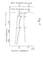
- the PVDF film coated with A1 and used in Examples 1 and 2 was used in this Example too.
- a Cu reflective layer was used also as an electrode, and the thickness thereof was varied from 0 to 340 ⁇ m. When the thickness of the Cu reflective layer was 0, both surfaces of the PVDF film were coated with Al by means of evaporation.
- the holder substrate was made of PMMA, and water was used as the transmission medium for the ultrasonic waves. The samples were subjected to evaluation of the frequency characteristics and the result is shown in FIG. 7.
- the thickness in ⁇ m of the Cu reflective layer is indicated on the abscissa, and the peak transfer loss in dB, the relative bandwidth and the peak frequency in MHz are indicated on the ordinate.
- the dash-and-dot line curve relates to the peak transfer loss, the solid line curve to the relative bandwidth, ⁇ f/f n , and the dotted line curve to the peak frequency.
- Values relating to the conventional prior art are marked with P l , W 1 and f l , respectively.
- the range on the abscissa between points d l (20 ⁇ m) and d 2 (120 ⁇ m) corresponds to the scope of the present invention.
- Values relating to the present invention in Example 1 are indicated at P 2 , W 2 and f 2 , respectively.
- the thickness of the reflective layer is reduced,in accordance with the present invention, to an extent of 1/8 to 3/4, more specifically about 1/4, of the conventional thickness.
- This remarkable reduction in thickness of the reflective layer assures production of an ultrasonic transducer with a high transfer efficiency and a broad available frequency-band.
- the reduced thickness retains the advantages of the piezoelectric polymer material such as high flexibility and easiness in processing.
- the reduced thickness also allows application of etching technique or other fine treatment.
- Use of such a thin reflective layer minimizes detrimental influence on the functional characteristics of the ultrasonic transducer, which may otherwise be caused by the material of the holder substrate being changed.
- piezoelectric materials of any other type having low acoustic impedance, can be used for the transducer in accordance with the present invention.
Landscapes
- Engineering & Computer Science (AREA)
- Physics & Mathematics (AREA)
- Acoustics & Sound (AREA)
- Multimedia (AREA)
- Mechanical Engineering (AREA)
- Transducers For Ultrasonic Waves (AREA)
- Length Measuring Devices Characterised By Use Of Acoustic Means (AREA)
- Ultra Sonic Daignosis Equipment (AREA)
Applications Claiming Priority (2)
| Application Number | Priority Date | Filing Date | Title |
|---|---|---|---|
| JP15177/79 | 1979-02-13 | ||
| JP54015177A JPS599000B2 (ja) | 1979-02-13 | 1979-02-13 | 超音波トランスデユ−サ |
Publications (2)
| Publication Number | Publication Date |
|---|---|
| EP0014693A1 true EP0014693A1 (de) | 1980-08-20 |
| EP0014693B1 EP0014693B1 (de) | 1983-06-08 |
Family
ID=11881525
Family Applications (1)
| Application Number | Title | Priority Date | Filing Date |
|---|---|---|---|
| EP80850016A Expired EP0014693B1 (de) | 1979-02-13 | 1980-02-13 | Verbesserter Ultraschall-Wandler |
Country Status (5)
| Country | Link |
|---|---|
| US (1) | US4296349A (de) |
| EP (1) | EP0014693B1 (de) |
| JP (1) | JPS599000B2 (de) |
| AU (1) | AU530471B2 (de) |
| DE (1) | DE3063645D1 (de) |
Cited By (8)
| Publication number | Priority date | Publication date | Assignee | Title |
|---|---|---|---|---|
| EP0121690A2 (de) * | 1983-03-07 | 1984-10-17 | Hitachi, Ltd. | Akustisches Mikroskop |
| EP0193048A2 (de) * | 1985-02-23 | 1986-09-03 | TERUMO KABUSHIKI KAISHA trading as TERUMO CORPORATION | Ultraschallwandler |
| FR2669120A1 (fr) * | 1990-11-13 | 1992-05-15 | Thomson Csf | Modulateur spatial bidimensionnel de lumiere a commande piezoelectrique, comprenant un reseau de bragg. |
| US5143087A (en) * | 1990-03-01 | 1992-09-01 | Shirit Yarkony | Analysis and treatment of swallowing dysfunction |
| EP0550193A1 (de) * | 1991-12-30 | 1993-07-07 | Xerox Corporation | Verfahren zum Ausschleudern von Tintentropfen in einem akustischen Tintendrucker sowie piezoelektrischer Wandler für einen Tintendrucker |
| CN100365840C (zh) * | 2005-11-30 | 2008-01-30 | 南京大学 | 平面型复合结构超声换能器 |
| CN107703187A (zh) * | 2016-08-09 | 2018-02-16 | 太阳诱电株式会社 | 气体传感器 |
| EP3164191A4 (de) * | 2014-07-03 | 2018-03-07 | Bkr Ip Holdco Llc | Verfahren und vorrichtung zur durchführung von alternierenden ultraschallübertragungen ohne kavitation |
Families Citing this family (31)
| Publication number | Priority date | Publication date | Assignee | Title |
|---|---|---|---|---|
| JPS5675686A (en) * | 1979-11-26 | 1981-06-22 | Kureha Chem Ind Co Ltd | Ultrasonic video device |
| US4387720A (en) * | 1980-12-29 | 1983-06-14 | Hewlett-Packard Company | Transducer acoustic lens |
| US4401910A (en) * | 1981-11-30 | 1983-08-30 | Analogic Corporation | Multi-focus spiral ultrasonic transducer |
| FR2531298B1 (fr) * | 1982-07-30 | 1986-06-27 | Thomson Csf | Transducteur du type demi-onde a element actif en polymere piezoelectrique |
| JPS5959000A (ja) * | 1982-09-28 | 1984-04-04 | Toshiba Corp | 凹面型超音波探触子及びその製造方法 |
| GB8325861D0 (en) * | 1983-09-28 | 1983-11-02 | Syrinx Presicion Instr Ltd | Force transducer |
| US4544859A (en) * | 1984-07-06 | 1985-10-01 | The United States Of America As Represented By The United States Department Of Energy | Non-bonded piezoelectric ultrasonic transducer |
| US5127410A (en) * | 1990-12-06 | 1992-07-07 | Hewlett-Packard Company | Ultrasound probe and lens assembly for use therein |
| US5744898A (en) * | 1992-05-14 | 1998-04-28 | Duke University | Ultrasound transducer array with transmitter/receiver integrated circuitry |
| US5311095A (en) * | 1992-05-14 | 1994-05-10 | Duke University | Ultrasonic transducer array |
| US5329496A (en) * | 1992-10-16 | 1994-07-12 | Duke University | Two-dimensional array ultrasonic transducers |
| US5309411A (en) * | 1992-12-08 | 1994-05-03 | Dehua Huang | Transducer |
| US5465724A (en) * | 1993-05-28 | 1995-11-14 | Acuson Corporation | Compact rotationally steerable ultrasound transducer |
| US5608692A (en) * | 1994-02-08 | 1997-03-04 | The Whitaker Corporation | Multi-layer polymer electroacoustic transducer assembly |
| US20050084122A1 (en) * | 1998-09-24 | 2005-04-21 | American Technology Corporation | Method for constructing a parametric transducer having an emitter film |
| US6685647B2 (en) * | 2001-06-28 | 2004-02-03 | Koninklijke Philips Electronics N.V. | Acoustic imaging systems adaptable for use with low drive voltages |
| US20040020883A1 (en) * | 2002-08-02 | 2004-02-05 | Brokaw Paul E. | Adhesive mounted storage rack, method, and kit |
| US7360417B2 (en) * | 2005-01-10 | 2008-04-22 | Gems Sensors, Inc. | Fluid level detector |
| US7443082B2 (en) * | 2006-03-03 | 2008-10-28 | Basf Corporation | Piezoelectric polymer composite article and system |
| US20080125658A1 (en) * | 2006-09-01 | 2008-05-29 | General Electric Company | Low-profile acoustic transducer assembly |
| JP2009061112A (ja) * | 2007-09-06 | 2009-03-26 | Ge Medical Systems Global Technology Co Llc | 超音波探触子および超音波撮像装置 |
| US7621028B2 (en) * | 2007-09-13 | 2009-11-24 | General Electric Company | Method for optimized dematching layer assembly in an ultrasound transducer |
| WO2009134434A1 (en) | 2008-05-02 | 2009-11-05 | Dymedix Corporation | Agitator to stimulate the central nervous system |
| US20100056855A1 (en) | 2008-08-22 | 2010-03-04 | Dymedix Corporation | Closed loop neuromodulator |
| DE102010028435A1 (de) | 2009-05-19 | 2010-11-25 | Ebs Ink-Jet Systeme Gmbh | Druckkopf eines Tintenstrahldruckers und Verfahren zum Reinigen einer Düse |
| DE102010063442A1 (de) * | 2010-12-17 | 2012-06-21 | Robert Bosch Gmbh | Schallwellenbasierter Sensor mit einer Schutzschicht zur Umfelddetektion und Verwendung desselben |
| CN102670242B (zh) * | 2011-04-07 | 2014-05-28 | 南京大学 | 一种超声聚焦换能器 |
| CN104984890B (zh) * | 2015-06-06 | 2017-12-08 | 中国科学院合肥物质科学研究院 | 一种柔性聚焦mems超声波发生器及其制备方法 |
| US11521500B1 (en) * | 2018-10-17 | 2022-12-06 | Amazon Technologies, Inc. | Unmanned aerial systems with range finding |
| US11417309B2 (en) * | 2018-11-29 | 2022-08-16 | Ascent Venture, Llc. | Ultrasonic transducer with via formed in piezoelectric element and method of fabricating an ultrasonic transducer including milling a piezoelectric substrate |
| US20210283656A1 (en) | 2020-03-12 | 2021-09-16 | Ascent Ventures, Llc | High bandwidth ultrasonic transducer with metal backing layer and method of fabrication |
Citations (3)
| Publication number | Priority date | Publication date | Assignee | Title |
|---|---|---|---|---|
| FR2161949A1 (de) * | 1971-11-05 | 1973-07-13 | Kureha Chemical Ind Co Ltd | |
| US3928777A (en) * | 1974-08-26 | 1975-12-23 | Dellorfano Jr Fred M | Directional ultrasonic transducer with reduced secondary lobes |
| DE2718772A1 (de) * | 1976-04-27 | 1977-11-03 | Tokyo Shibaura Electric Co | Sonde fuer eine ultraschall- diagnosevorrichtung |
Family Cites Families (5)
| Publication number | Priority date | Publication date | Assignee | Title |
|---|---|---|---|---|
| US2875354A (en) * | 1954-01-29 | 1959-02-24 | Branson Instr | Piezoelectric transducer |
| US3365593A (en) * | 1965-10-21 | 1968-01-23 | Phillips Petroleum Co | Piezoelectric transducers |
| JPS5318893B2 (de) * | 1971-12-03 | 1978-06-17 | ||
| JPS5431825B2 (de) * | 1973-08-08 | 1979-10-09 | ||
| US4184094A (en) * | 1978-06-01 | 1980-01-15 | Advanced Diagnostic Research Corporation | Coupling for a focused ultrasonic transducer |
-
1979
- 1979-02-13 JP JP54015177A patent/JPS599000B2/ja not_active Expired
-
1980
- 1980-02-12 AU AU55466/80A patent/AU530471B2/en not_active Ceased
- 1980-02-12 US US06/120,782 patent/US4296349A/en not_active Expired - Lifetime
- 1980-02-13 EP EP80850016A patent/EP0014693B1/de not_active Expired
- 1980-02-13 DE DE8080850016T patent/DE3063645D1/de not_active Expired
Patent Citations (3)
| Publication number | Priority date | Publication date | Assignee | Title |
|---|---|---|---|---|
| FR2161949A1 (de) * | 1971-11-05 | 1973-07-13 | Kureha Chemical Ind Co Ltd | |
| US3928777A (en) * | 1974-08-26 | 1975-12-23 | Dellorfano Jr Fred M | Directional ultrasonic transducer with reduced secondary lobes |
| DE2718772A1 (de) * | 1976-04-27 | 1977-11-03 | Tokyo Shibaura Electric Co | Sonde fuer eine ultraschall- diagnosevorrichtung |
Non-Patent Citations (5)
| Title |
|---|
| ELECTRONICS LETTERS, Vol. 12, No. 16, Aug. 1976 L. BUI et al.: "Experimental Broadband ultrasonic transducers using PVF2 piezoelectric film" pages 393, 394. * Abstract, page 393, column 1, paragraph 2, column 2, paragraphs 2, 3 * * |
| J. OF THE ACOUSTICAL SOC. OF AMERICA, Vol. 64, No. 6, 1978 F. MICHERON et al.: "Moulded piezoelectric transducers using polar polymers", pages 1720, 1721 * Abstract, page 1720, paragraphs 1, 4, 5 * * |
| JAPAN J. APPL. PHYS. 8, 1969, H. KAWAI: "The Piezoelectricity of Polyvinylidene Fluoride", pages 975, 976 * Table 1 * * |
| ULTRASONICS, Vol. 12, No. 3, May 1974 SIMANSKI, JP. et al.: "Loading transducers for non- destructive testing and signal processing by acoustic bulk waves", pages 100-105 * Page 103, example 2; page 104; page 105, figures 8-13 * * |
| ULTRASONICS, Vol. 14, No. 1, Jan. 1976 N. MURAYAMA et al.: "The strong piezoelectricity in polyvinylidene fluoride (PVDF)", pages 15-23 * Page 22, figure 13, column 2, paragraph 2 * * |
Cited By (12)
| Publication number | Priority date | Publication date | Assignee | Title |
|---|---|---|---|---|
| EP0121690A2 (de) * | 1983-03-07 | 1984-10-17 | Hitachi, Ltd. | Akustisches Mikroskop |
| EP0121690A3 (en) * | 1983-03-07 | 1985-07-31 | Hitachi, Ltd. | Acoustic microscope |
| EP0193048A2 (de) * | 1985-02-23 | 1986-09-03 | TERUMO KABUSHIKI KAISHA trading as TERUMO CORPORATION | Ultraschallwandler |
| EP0193048A3 (en) * | 1985-02-23 | 1987-02-04 | Terumo Kabushiki Kaisha Trading As Terumo Corporation | Ultrasonic transducer |
| US4795935A (en) * | 1985-02-23 | 1989-01-03 | Terumo Corporation | Ultrasonic transducer |
| US5143087A (en) * | 1990-03-01 | 1992-09-01 | Shirit Yarkony | Analysis and treatment of swallowing dysfunction |
| FR2669120A1 (fr) * | 1990-11-13 | 1992-05-15 | Thomson Csf | Modulateur spatial bidimensionnel de lumiere a commande piezoelectrique, comprenant un reseau de bragg. |
| EP0486356A1 (de) * | 1990-11-13 | 1992-05-20 | Thomson-Csf | Piezoelektrisch betriebener zweidimensionaler Raumlichtmodulator mit einem Bragg-Gitter |
| EP0550193A1 (de) * | 1991-12-30 | 1993-07-07 | Xerox Corporation | Verfahren zum Ausschleudern von Tintentropfen in einem akustischen Tintendrucker sowie piezoelektrischer Wandler für einen Tintendrucker |
| CN100365840C (zh) * | 2005-11-30 | 2008-01-30 | 南京大学 | 平面型复合结构超声换能器 |
| EP3164191A4 (de) * | 2014-07-03 | 2018-03-07 | Bkr Ip Holdco Llc | Verfahren und vorrichtung zur durchführung von alternierenden ultraschallübertragungen ohne kavitation |
| CN107703187A (zh) * | 2016-08-09 | 2018-02-16 | 太阳诱电株式会社 | 气体传感器 |
Also Published As
| Publication number | Publication date |
|---|---|
| DE3063645D1 (en) | 1983-07-14 |
| JPS55106571A (en) | 1980-08-15 |
| AU5546680A (en) | 1980-08-21 |
| AU530471B2 (en) | 1983-07-14 |
| JPS599000B2 (ja) | 1984-02-28 |
| US4296349A (en) | 1981-10-20 |
| EP0014693B1 (de) | 1983-06-08 |
Similar Documents
| Publication | Publication Date | Title |
|---|---|---|
| EP0014693B1 (de) | Verbesserter Ultraschall-Wandler | |
| EP0018614B1 (de) | Elektroakustisches Wandlerelement | |
| US6049159A (en) | Wideband acoustic transducer | |
| Manthey et al. | Ultrasonic transducers and transducer arrays for applications in air | |
| EP0128049B1 (de) | Ultraschallsende mit einem absorbierenden Träger | |
| CA1151285A (en) | Acoustic transducer with a quarter wavelength adaptation layer as a receiver | |
| US6258034B1 (en) | Apodization methods and apparatus for acoustic phased array aperture for diagnostic medical ultrasound transducer | |
| US5511296A (en) | Method for making integrated matching layer for ultrasonic transducers | |
| US6673016B1 (en) | Ultrasound selectable frequency response system and method for multi-layer transducers | |
| US20030032884A1 (en) | Ultrasound transducer for improving resolution in imaging system | |
| GB2098828A (en) | Ultrasonic transducer for single frequency applications | |
| US4635484A (en) | Ultrasonic transducer system | |
| EP0193048A2 (de) | Ultraschallwandler | |
| US6106474A (en) | Aerogel backed ultrasound transducer | |
| US4016530A (en) | Broadband electroacoustic converter | |
| WO2001062154A1 (en) | Ultrasound transducer system and method for harmonic imaging | |
| EP0015886A1 (de) | Verbessertes elektro-akustisches Wandler-Element | |
| US6124664A (en) | Transducer backing material | |
| Hurmila et al. | Ultrasonic transducers using PVDF | |
| Brown | The effects of material selection for backing and wear protection/quarter-wave matching of piezoelectric polymer ultrasound transducers | |
| JP2002209292A (ja) | 超音波探触子 | |
| Shaulov et al. | Performance of ultrasonic transducers made from composite piezoelectric materials | |
| JP2814903B2 (ja) | 超音波探触子 | |
| JPH01101455A (ja) | 超音波顕微鏡用トランスジューサ | |
| Hladky-Hennion et al. | Finite element modeling of transduction materials with application to piezoelectric hollow sphere transducers |
Legal Events
| Date | Code | Title | Description |
|---|---|---|---|
| PUAI | Public reference made under article 153(3) epc to a published international application that has entered the european phase |
Free format text: ORIGINAL CODE: 0009012 |
|
| AK | Designated contracting states |
Designated state(s): CH DE FR GB NL |
|
| 17P | Request for examination filed |
Effective date: 19810216 |
|
| GRAA | (expected) grant |
Free format text: ORIGINAL CODE: 0009210 |
|
| AK | Designated contracting states |
Designated state(s): CH DE FR GB NL |
|
| REF | Corresponds to: |
Ref document number: 3063645 Country of ref document: DE Date of ref document: 19830714 |
|
| ET | Fr: translation filed | ||
| PGFP | Annual fee paid to national office [announced via postgrant information from national office to epo] |
Ref country code: CH Payment date: 19831222 Year of fee payment: 5 |
|
| PLBI | Opposition filed |
Free format text: ORIGINAL CODE: 0009260 |
|
| 26 | Opposition filed |
Opponent name: SIEMENS AKTIENGESELLSCHAFT, BERLIN UND MUENCHEN Effective date: 19840308 |
|
| PGFP | Annual fee paid to national office [announced via postgrant information from national office to epo] |
Ref country code: FR Payment date: 19841228 Year of fee payment: 6 |
|
| PGFP | Annual fee paid to national office [announced via postgrant information from national office to epo] |
Ref country code: DE Payment date: 19850322 Year of fee payment: 6 |
|
| PGFP | Annual fee paid to national office [announced via postgrant information from national office to epo] |
Ref country code: NL Payment date: 19870228 Year of fee payment: 8 |
|
| RDAG | Patent revoked |
Free format text: ORIGINAL CODE: 0009271 |
|
| STAA | Information on the status of an ep patent application or granted ep patent |
Free format text: STATUS: PATENT REVOKED |
|
| 27W | Patent revoked |
Effective date: 19880218 |
|
| GBPR | Gb: patent revoked under art. 102 of the ep convention designating the uk as contracting state | ||
| REG | Reference to a national code |
Ref country code: CH Ref legal event code: PL |
|
| NLR2 | Nl: decision of opposition | ||
| APAH | Appeal reference modified |
Free format text: ORIGINAL CODE: EPIDOSCREFNO |