EP0014665A1 - Verfahren und System zum Einblenden von Bildern beim Farbfernsehen - Google Patents
Verfahren und System zum Einblenden von Bildern beim Farbfernsehen Download PDFInfo
- Publication number
- EP0014665A1 EP0014665A1 EP80400202A EP80400202A EP0014665A1 EP 0014665 A1 EP0014665 A1 EP 0014665A1 EP 80400202 A EP80400202 A EP 80400202A EP 80400202 A EP80400202 A EP 80400202A EP 0014665 A1 EP0014665 A1 EP 0014665A1
- Authority
- EP
- European Patent Office
- Prior art keywords
- image
- primary
- foreground
- signal
- gain
- Prior art date
- Legal status (The legal status is an assumption and is not a legal conclusion. Google has not performed a legal analysis and makes no representation as to the accuracy of the status listed.)
- Granted
Links
Images


Classifications
-
- H—ELECTRICITY
- H04—ELECTRIC COMMUNICATION TECHNIQUE
- H04N—PICTORIAL COMMUNICATION, e.g. TELEVISION
- H04N9/00—Details of colour television systems
- H04N9/64—Circuits for processing colour signals
- H04N9/74—Circuits for processing colour signals for obtaining special effects
- H04N9/75—Chroma key
Definitions
- the present invention relates to a method and a system for overlaying images in color television.
- a method of overlaying a foreground image into a background image in color television according to which a first video source provides the foreground image in front of a background having, relative to a system with three primary colorimetric coordinates, a colorimetric domain inside the colorimetric domain of the foreground image, and a second video source provides a background image, and according to which the primary components of the video signal of the composite foreground and background image are transmitted to means for producing a control signal having a first level when the first video source delivers the foreground image in order to controlling the transmission of the foreground image and having a second level when the first video source delivers the background image in order to control the transmission of the background image.
- the keying system implementing this method comprises means having their inputs receiving the primary components separated from the composite foreground and background image to produce primary gain control signals having respectively said second level, when the amplitude of the primary component associated with the video signal of the composite image is between two first reference voltages delimiting the trichromatic domain of the background image, and said first level when the amplitude of the primary component associated with the signal video of the composite foreground and background image is not included at least between the first two reference voltages, means for multiplying said primary control signals into said control signal, means receiving the video signals the composite image and the background image to select under the control of the control signal the transmission of the video signals of the front image - scene and of the background image and means for mixing the selected video signals into a resulting video signal transmitting the foreground image embedded in the background image.
- the overlay control signal which controls the removal of the background in the foreground image and the removal of the area corresponding to the foreground image to be embedded in the background image , is a two-level logic signal which is obtained by logic multiplication means. A first level, low for example, is produced when a point in the foreground image is detected, and a second level, or high level, is produced when a point in the background image is detected.
- the border between the foreground image and the background image substituted for the background image in the resulting inlaid image is very clear, which does not allow obtaining effects.
- transparency when the foreground image comprises a transparent object, such as a glass or a bottle, filmed by the first source.
- the composite image presents the background through the transparency of the object and n belongs more, to a large extent, to the background colorimetric range.
- the background image when inlaying, instead of seeing the background image, such as a decor, through the transparent object, the background is seen through the object. This same phenomenon can be repeated when the foreground image is of a character whose hair is, for example, disheveled.
- systems for image embedding in color television are also known, systems also known as systems for combining a foreground image and a backscene image into a composite image, for which the background of the foreground image is one-color and, more precisely, is of a pure color belonging to one of the primary components, generally the blue component, hence. process designation with "blue single-color screen or background".
- the background of the foreground image is one-color and, more precisely, is of a pure color belonging to one of the primary components, generally the blue component, hence. process designation with "blue single-color screen or background”.
- US patents 3,778,542, 3,595,987 pending French applications 2,128,156 and German 2,107,524) and 4,007,487, and German patent application 2,749,154-9.
- the signal controlling the incrustation is obtained by the selection of said determined threshold, which varies as a function of the amplitude of the selected primary component of the foreground image, for example the blue primary, which is weighted by a relation one or two of the other primary components (red and green) of the foreground image.
- the disadvantage of this weighting is that it must be adjusted manually for each pre-scene image sequence in dependence on the dominant colorimetric tone thereof. However, it does, in some cases.
- the foreground image must not have image points having a corresponding primary component whose amplitude is greater than that of the background.
- the trichromatic domain of the foreground image (such as a character) is limited by a plane which is parallel to the plane of the coordinates of the other primary components (red and green) and which intersects the coordinate axis of the selected primary component (blue at a point having as coordinate said lower threshold of the primary component of the background.
- the domain containing the origin of the trichromatic coordinate system and limited by said plane is that of the image of front stage.
- the object of the present invention is to overcome the above-mentioned transparency drawbacks and to distinguish the trichromatic transition domain between the trichromatic domains of the foreground image and of the background image in the composite image. so that part of the foreground image and part of the background image are simultaneously transmitted in a variable ratio when the transition domain is detected.
- the image inlay process in color television as defined in the introduction is characterized, in accordance with the invention, in that the control signal comprises intermediate levels between the first and second levels when the first video source delivers points from the composite image belonging to a trichromatic transition domain which surrounds the colorimetric domain of the background image and which is surrounded by the colorimetric domain of the foreground image, in order to simultaneously control the transmission of points of the image composite belonging to the transition area and backstage filing points.
- An overlay system implementing this method and relating to that defined in the introduction is characterized in that the means for producing a primary gain control signal detect the amplitudes of the primary component associated with the video signal of the composite image included in two intervals of reference voltages, which delimit the trichromatic transition domain and which each have for limits one of said first reference voltages and a second reference voltage delimiting the colorimetric domain of the image proscenium, in order to transmit an intermediate level in quasi-linear relation with the ratio of the amplitude of said primary component and one of the limits of the interval comprising this amplitude, and in that said means for selecting video signals of the foreground image and the background image comprise amplification means with variable gain under the control of said control signal ⁇ p or amplify the video signals of the composite image and the background image respectively with a gain substantially proportional to (1- ⁇ ) and ⁇ .
- the composite image is diminished simultaneously with the amplification of the image behind the scenes when the border of the transition domain contiguous to the color domain of the foreground image is detected.
- the part corresponding to the transition domain in the resulting inlaid image is composed of a fuzzy mixture of the foreground and background images.
- the color television picture-in-picture system as shown in FIG. 1 receives at its inputs 1b and 1a two composite video signals which are transmitted respectively from a first video source providing the composite signal of a composite color television picture b and second from a / video source providing the signal composite of a background color television image a.
- L.image b is for example that representing a character p moving in front of a background in colors f
- image a is for example a color decor to replace the background f.
- the color field of image p is substantially the complement of the color field of image f in the total color system.
- the first and second video sources are synchronized and are generally electronic color cameras but can also be other video sources which are commonly used in the technique of video specialization, such as video recorders, slide transmitters, etc.
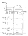
- FIG. 2 the classical trichromatic Cartesian system, relating to the three monochrematic coordinates of the primary red R, green V and blue B components of a color video signal
- Domain D is contained in domain D '.
- This transition domain T corresponds to the “fuzzy” mixture of colors of the common edges of the images f and p or, more generally, to “common or confused” image parts of the pet images f.
- Such parts of images are for example the fluffy hair of a character or a transparent object, such as a glass or a bottle, through which the background appears f.
- the resulting image inlaid in colors presented said parts common with said fund f. This produced an annoying border effect and also an unfair reproduction of the decor.
- the system of FIG. 1 makes it possible to eliminate this defect because, in the image inlaid in resulting colors r transmitted by the output 2 of the system, a glass of the image p for example makes appear through this one from the corresponding decorations.
- the two reference voltage intervals of the transition domain T relative to each color coordinate R, G, B respectively VR 1 - VR ' 1 and VR' 2 - VR 2 , VV 1 - VV ' 1 and VV2 - VV 2 , VB 1 - VB ' 1 and VB' 2 - VB 2 can be different and can be selected independently by the operator, one with respect to the other and each with respect to the other four of the other two primary components , as will be seen below.
- the background domain is a point of coordinates VB, 0, O or an open segment collinear with the axis of coordinate VB, representing the values VB greater than VB 1 .
- the colorimetric domain of the foreground image such as a character, is defined by all the points having their primary component selected blue such as VB ⁇ VB 1 .
- the video signal b is transmitted to the input of a video splitter 3 which filters the three primary components b R , b Y and b B of the image b to transmit them to the three inputs 40 R , 40 V , 40 B of a gain control circuit 4.
- the images b and a can be transmitted from the first and second sources directly in the form of components.
- primaries b R , b V , b B and a R , a V , a B or some other combination of these are transmitted directly to the inputs 40 R , 40 V , 40B and suitable video mixers restore the inputs 1a and 1b the composite video signals a and b.
- the composite video signals a and b are transmitted respectively to the video inputs 50a, 50b of variable gain amplifiers 5a, 5b.
- Amplifiers 5a and 5 have a maximum gain G and have a respective gain variation ⁇ G and (1- ⁇ ) G correlated to the control signal ⁇ transmitted by output 44 of circuit 4.
- This signal is an analog voltage signal varying between a first level says low equal to zero and a second level says high equal to unity.
- This signal ⁇ controls the overlay of the part of the video signal b representing the proscenium image p in the video signal a by eliminating the edge effects.
- the gain control circuit describing the gain control signal ⁇ is described.
- a primary component b R , b V , b B of the video signal b are connected in series with a detector 41 RI 41 V , 41 B which detects primary colorimetric intervals belonging to the domains D , D 'and T and an analog multiplication circuit 42 R , 42 V , 4 2 B respectively.
- Only the detector 41 R and the multiplication circuit 42 R are detailed in FIG. 1, the others being respectively identical, with the settings near the reference voltages limiting the colorimetric intervals
- the detector 41R comprises two operational amplifiers with variable gain 411 and 412 respectively having their reverse (-) and direct (+) inputs connected to the 40 Ro terminal.
- Each amplifier 411, 412 is a non-linear amplifier, that is to say say having a gain varying as a quasi-linear function of the voltage applied to its entry into an intake window determined by its gain and having a low output impedance.
- the other input, respectively direct (+) and inverse (-), of an amplifier 411, 412 receives a voltage signal VR 1 , VR2, adjustable by means of a potentiometer 413,414 and corresponding to one of the limits of reference voltage of the red primary of domain D of the background f.
- the setting of potentiometers 413 and 414 can be common for a predetermined constant VIR 2 -VR 1 difference .
- Amplifier 411 amplifies any signal of amplitude b R between the first limits VR 1 and VR 1 of the transition domain T with a gain g 1 proportional to k 1 (b R - VR ' 1 ) / (VR 1 - VR ' 1 ), where k 1 is a constant depending on the gain control of ampLifier 411 and a function of the voltage interval (VR 1 -VR' 1 ).
- the amplifier 412 amplifies any signal of amplitude b R comprised between the second limits VR 2 and of the transition domain T with a gain g 2 proportional to k 2 (b R - ) / (VR 2 - ) where k 2 is a constant depending on the gain setting of amplifier 412 and a function of the voltage interval (VR 2 - ). So when the signal of the red primary component b R represented in Fig.
- the signals ⁇ R1 and ⁇ R2 are both at the high level, and when b R is at an intermediate level belonging to the transition domain T, the signals ⁇ R1 and ⁇ R2 have a variation between 0 and 1 analogous to the amplitude of b R respectively when ⁇ b R ⁇ VR 1 and when VR 2 ⁇ b R ⁇
- the signals ⁇ R1 and ⁇ R2 transmitted by the outputs of amplifiers 411 and 412 are shown in Figs. 3B and 3C in correspondence with the red primary component signal b R shown in FIG. 3A.
- the combination by analog multiplication of the signals ⁇ R1 and ⁇ R2 into a primary gain control signal ⁇ R is carried out in a circuit 42 R such as a conventional analog AND gate which comprises on the output side a transistor 423 and on the input side two diodes 424 , 425, as shown in FIG. 1, or two transistors mounted in diodes.
- the two other analog multiplication circuits 42 V and 42 B reproduce primary gain control signals ⁇ V and ⁇ B which delimit, analogously to the signal ⁇ R shown in FIG. 3D, the green and blue monochromatic intervals associated with the domains D, D 'and T.
- the analog multiplication of the three signals ⁇ R. ⁇ V ⁇ B is performed by an analog circuit 43 such as a conventional analog AND gate.
- This circuit 43 comprises, next to its three inputs, three diodes 430 R , 430 V , 430 B , which respectively receive the signals ⁇ R , ⁇ V , ⁇ B , as shown in FIG. 1, or three transistors mounted as diodes and, next to its output 44, a transistor 431.
- the output 44 of the circuit 43 transmits the overall gain control signal ⁇ to the variable gain amplifiers 5a and 5b.
- the system for overlaying color television images comprises, if necessary, the video splitter 3b and a video splitter 3a receiving the composite video signal a, via the input 1a.
- the video splitters 3a and 3b filter and separate the primary components a R , a V a B and b R , b V , b B from the video signals a and b received.
- the three outputs of the video splitter 3b respectively transmit the separate primary components b R , b V , b B to the three video inputs 50 bR , 50 bV , 50 bB of the first three variable gain amplifiers 5 bR , 5 bV , 5 bB .
- the three outputs of the video splitter 3a respectively transmit the separate primary components a R , a V , a B to the three video inputs 50 aR , 50 aV , 50 aB of three second variable gain amplifiers 5 aR , 5 aV , 5 aB .
- These first and second amplifiers are analogous to the amplifiers 5a and 5b in FIG.
- the inputs 51 bR , 51 bV , 51 bB of the amplifiers 5 bR , 5 bV , 5 bB each receive a second reverse primary gain control signal, respectively (1- , (1- ), (1 - ), by an analog inverter circuit 52 bR , 52 bV , 52 bB .
- the inputs of each pair of an inverter circuit associated with the signal channel b and of a variable gain amplifier associated with the signal channel a, relative to the same primary component, receive said second primary gain control signal ⁇ R ', which is transmitted by the respective output among three, 44 R , 44 VI 44B of a gain control circuit 4 '.
- This circuit 4 ′ includes the gain control circuit 4 of FIG. 1 and, in addition, a detector 45 of the colorimetric domain D + T and a set of three analog multiplication circuits such as analog gates ET 46 R , 46 V , 46 B.
- the component circuits 41 R , 41 V , 41 B , 42 R , 42 V , 42 B and 43 between the terminals 40 R , 40 V , 40 B , connected respectively to the outputs of the video splitter 3b, and the output terminal 44 of the circuit 4, are identical to the circuits described with reference to FIG. 1.
- the input of the detector 45 is connected to the terminal 44 and receives the gain control signal ⁇ .
- the output of detector 45 is connected to first inputs of the analog circuits ET 46R, 46 V , 46 B.
- This detector 45 is composed of suitable flip-flops or of a voltage comparator. It detects the transition of a low level at an intermediate level of the signal and vice versa in order to transmit a signal ⁇ D + T whose first level known as low delimits the domain D ′ of the proscenium image p, when the signal ⁇ is at the first level known as low, and whose second level called high delimits all of the D + T domains, when the signal ⁇ is at the second level called high or at an intermediate level.
- the second inputs of the analog circuits ET 46 R , 46 v and 46 B are connected respectively to the outputs of the analog circuits ET 42 R , 42 v , 42 B which transmit the first primary gain control signals ⁇ R , ⁇ V , ⁇ B .
- Each second gain control signal primary gain control signal is transmitted respectively by output 44 R , 44 V , 44 B of an analog AND gate 46 R , 46 V , 46 B to the input of the associated inverter circuit 52 bR , 52 bV , 52 bB and to input 51 aR , 51 aV , 51 aB of the associated variable gain amplifier 5 aR , 5 aV , 5 aB .
- Each second primary control signal is analogous to the signal ⁇ with the difference that the rising and falling slopes at intermediate levels are no longer a global contribution of the primary components of image b, but an individual contribution of the associated primary component b R , b V , b B. as a result, the resulting image r 'transmitted by the output 2' of a conventional video mixer 6 ', whose six inputs are respectively connected to the outputs of the six variable gain amplifiers 5 bR to 5 aB , reproduces the domain more faithfully Transition T. Indeed, according to the first variant, shown in FIG.
- the intermediate levels of the signal ⁇ control a gain variation common to the primary components in the amplifiers Sa and 5b, that is to say relative to the luminance of the video signals a and b, while according to the second variant the variations gain relative to each primary component of the transition domain T are independently controlled.
Applications Claiming Priority (2)
| Application Number | Priority Date | Filing Date | Title |
|---|---|---|---|
| FR7903521 | 1979-02-12 | ||
| FR7903521A FR2448821A1 (fr) | 1979-02-12 | 1979-02-12 | Procede et systeme d'incrustation d'images en television en couleurs |
Publications (2)
| Publication Number | Publication Date |
|---|---|
| EP0014665A1 true EP0014665A1 (de) | 1980-08-20 |
| EP0014665B1 EP0014665B1 (de) | 1983-04-06 |
Family
ID=9221858
Family Applications (1)
| Application Number | Title | Priority Date | Filing Date |
|---|---|---|---|
| EP80400202A Expired EP0014665B1 (de) | 1979-02-12 | 1980-02-08 | Verfahren und System zum Einblenden von Bildern beim Farbfernsehen |
Country Status (5)
| Country | Link |
|---|---|
| US (1) | US4292649A (de) |
| EP (1) | EP0014665B1 (de) |
| JP (1) | JPS55107390A (de) |
| DE (1) | DE3062568D1 (de) |
| FR (1) | FR2448821A1 (de) |
Cited By (5)
| Publication number | Priority date | Publication date | Assignee | Title |
|---|---|---|---|---|
| FR2527033A1 (fr) * | 1982-05-17 | 1983-11-18 | Telediffusion Fse | Systeme d'incrustation d'images en television en couleurs |
| FR2561476A1 (fr) * | 1984-03-19 | 1985-09-20 | Production Creation Audiovisue | Dispositif d'incrustation d'images en television en couleurs |
| GB2176671A (en) * | 1985-05-31 | 1986-12-31 | Electrocraft Consultants Limit | Separation overlay |
| EP0776135A1 (de) * | 1995-11-23 | 1997-05-28 | Thomson Broadcast Systems | Verfahren und Vorrichtung zur Verarbeitung eines Signals das aus einem sich vor einem farbigen Hintergrund bewegenden Objekt gebildet wird |
| EP0776136A1 (de) * | 1995-11-23 | 1997-05-28 | Thomson Broadcast Systems | Verfahren und Vorrichtung zur Berechnung eines Farbstanzsignals für ein sich vor einem farbigen Hintergrund bewegendes Objekt |
Families Citing this family (20)
| Publication number | Priority date | Publication date | Assignee | Title |
|---|---|---|---|---|
| US4403249A (en) * | 1978-02-21 | 1983-09-06 | Dr. Ing. Rudolf Hell Gmbh. | Apparatus for mixing image signals to obtain a printing master |
| US5216755A (en) * | 1980-12-04 | 1993-06-01 | Quantel Limited | Video image creation system which proportionally mixes previously created image pixel data with currently created data |
| US5289566A (en) * | 1980-12-04 | 1994-02-22 | Quantel, Ltd. | Video image creation |
| US4374395A (en) * | 1980-12-24 | 1983-02-15 | Texas Instruments Incorporated | Video system with picture information and logic signal multiplexing |
| US4393394A (en) * | 1981-08-17 | 1983-07-12 | Mccoy Reginald F H | Television image positioning and combining system |
| FR2531290A1 (fr) * | 1982-07-30 | 1984-02-03 | Poirier Alain | Reseau de videocommunication entre des terminaux visiophoniques et une banque d'images |
| JPS60123978A (ja) * | 1983-12-08 | 1985-07-02 | Kubota Ltd | 色信号分離装置 |
| GB8420890D0 (en) * | 1984-08-16 | 1984-09-19 | Quantel Ltd | Video editing systems |
| FR2576733B1 (fr) * | 1985-01-28 | 1987-04-24 | Telediffusion Fse | Systeme de surimpression d'images |
| US4698666A (en) * | 1985-07-12 | 1987-10-06 | The Grass Valley Group, Inc. | Video key glow and border generator |
| GB8629832D0 (en) * | 1986-12-13 | 1987-01-21 | Quantel Ltd | Video graphics systems |
| GB8928058D0 (en) * | 1989-12-12 | 1990-02-14 | Crosfield Electronics Ltd | Digital image generation |
| US5724091A (en) | 1991-11-25 | 1998-03-03 | Actv, Inc. | Compressed digital data interactive program system |
| US7448063B2 (en) | 1991-11-25 | 2008-11-04 | Actv, Inc. | Digital interactive system for providing full interactivity with live programming events |
| US7079176B1 (en) | 1991-11-25 | 2006-07-18 | Actv, Inc. | Digital interactive system for providing full interactivity with live programming events |
| US5537141A (en) * | 1994-04-15 | 1996-07-16 | Actv, Inc. | Distance learning system providing individual television participation, audio responses and memory for every student |
| US5632007A (en) * | 1994-09-23 | 1997-05-20 | Actv, Inc. | Interactive system and method for offering expert based interactive programs |
| US5682196A (en) * | 1995-06-22 | 1997-10-28 | Actv, Inc. | Three-dimensional (3D) video presentation system providing interactive 3D presentation with personalized audio responses for multiple viewers |
| US7305691B2 (en) | 2001-05-07 | 2007-12-04 | Actv, Inc. | System and method for providing targeted programming outside of the home |
| US7075899B2 (en) | 2002-05-21 | 2006-07-11 | Actv, Inc. | System and method for providing private in-band data to digital set-top boxes in a broadcast environment |
Citations (7)
| Publication number | Priority date | Publication date | Assignee | Title |
|---|---|---|---|---|
| FR2128156A1 (de) * | 1969-02-20 | 1972-10-20 | Ass Motion Picture Tv Prod | |
| US3778542A (en) * | 1970-11-30 | 1973-12-11 | Technicolor | Blue screen travelling matte system |
| DE2612042A1 (de) * | 1975-03-21 | 1976-12-02 | Sonex Int Corp | Verschiebbares video-mattscheibensystem |
| US4007487A (en) * | 1975-09-25 | 1977-02-08 | The Association Of Motion Picture And Television Producers Inc. | Electronic composite photography with color control |
| FR2345030A1 (fr) * | 1976-03-15 | 1977-10-14 | Tektronix Inc | Appareil et procede pour produire des effets video, notamment en television en couleur |
| DE2749154A1 (de) * | 1976-11-03 | 1978-05-24 | Vlahos Gottschalk Res | Umfassendes elektronisches kompositionssystem |
| NL7710959A (en) * | 1977-10-06 | 1978-10-31 | Philips Nv | Chromatic key signal generator for colour TV - has switch=over circuit linking second video source via controlled amplifier linked to matrix circuit |
Family Cites Families (2)
| Publication number | Priority date | Publication date | Assignee | Title |
|---|---|---|---|---|
| FR2142820B1 (de) * | 1971-06-25 | 1975-04-18 | Ortf | |
| JPS5340417A (en) * | 1976-09-24 | 1978-04-13 | Mitsubishi Electric Corp | Change over valve |
-
1979
- 1979-02-12 FR FR7903521A patent/FR2448821A1/fr active Granted
-
1980
- 1980-02-08 EP EP80400202A patent/EP0014665B1/de not_active Expired
- 1980-02-08 DE DE8080400202T patent/DE3062568D1/de not_active Expired
- 1980-02-12 JP JP1489680A patent/JPS55107390A/ja active Granted
- 1980-02-14 US US06/121,779 patent/US4292649A/en not_active Expired - Lifetime
Patent Citations (7)
| Publication number | Priority date | Publication date | Assignee | Title |
|---|---|---|---|---|
| FR2128156A1 (de) * | 1969-02-20 | 1972-10-20 | Ass Motion Picture Tv Prod | |
| US3778542A (en) * | 1970-11-30 | 1973-12-11 | Technicolor | Blue screen travelling matte system |
| DE2612042A1 (de) * | 1975-03-21 | 1976-12-02 | Sonex Int Corp | Verschiebbares video-mattscheibensystem |
| US4007487A (en) * | 1975-09-25 | 1977-02-08 | The Association Of Motion Picture And Television Producers Inc. | Electronic composite photography with color control |
| FR2345030A1 (fr) * | 1976-03-15 | 1977-10-14 | Tektronix Inc | Appareil et procede pour produire des effets video, notamment en television en couleur |
| DE2749154A1 (de) * | 1976-11-03 | 1978-05-24 | Vlahos Gottschalk Res | Umfassendes elektronisches kompositionssystem |
| NL7710959A (en) * | 1977-10-06 | 1978-10-31 | Philips Nv | Chromatic key signal generator for colour TV - has switch=over circuit linking second video source via controlled amplifier linked to matrix circuit |
Cited By (10)
| Publication number | Priority date | Publication date | Assignee | Title |
|---|---|---|---|---|
| FR2527033A1 (fr) * | 1982-05-17 | 1983-11-18 | Telediffusion Fse | Systeme d'incrustation d'images en television en couleurs |
| EP0097068A1 (de) * | 1982-05-17 | 1983-12-28 | Etablissement Public de Diffusion dit "Télédiffusion de France" | Farbfernseh-bildeinblendsystem |
| FR2561476A1 (fr) * | 1984-03-19 | 1985-09-20 | Production Creation Audiovisue | Dispositif d'incrustation d'images en television en couleurs |
| GB2176671A (en) * | 1985-05-31 | 1986-12-31 | Electrocraft Consultants Limit | Separation overlay |
| EP0776135A1 (de) * | 1995-11-23 | 1997-05-28 | Thomson Broadcast Systems | Verfahren und Vorrichtung zur Verarbeitung eines Signals das aus einem sich vor einem farbigen Hintergrund bewegenden Objekt gebildet wird |
| EP0776136A1 (de) * | 1995-11-23 | 1997-05-28 | Thomson Broadcast Systems | Verfahren und Vorrichtung zur Berechnung eines Farbstanzsignals für ein sich vor einem farbigen Hintergrund bewegendes Objekt |
| FR2741770A1 (fr) * | 1995-11-23 | 1997-05-30 | Thomson Broadcast Systems | Procede de calcul d'une cle de decoupe d'un sujet evoluant devant un fond colore et dispositif mettant en oeuvre ce procede |
| FR2741769A1 (fr) * | 1995-11-23 | 1997-05-30 | Thomson Broadcast Systems | Procede de traitement du signal constitue par un sujet evoluant devant un fond colore et dispositif mettant en oeuvre ce procede |
| US5903318A (en) * | 1995-11-23 | 1999-05-11 | Thomson Broadcast Systems | Device and method for determining a key for clipping a subject moving against a colored background |
| US5923381A (en) * | 1995-11-23 | 1999-07-13 | Thomson Broadcast Systems | Device and method for processing a signal with a subject moving against a colored background |
Also Published As
| Publication number | Publication date |
|---|---|
| FR2448821A1 (fr) | 1980-09-05 |
| EP0014665B1 (de) | 1983-04-06 |
| US4292649A (en) | 1981-09-29 |
| DE3062568D1 (en) | 1983-05-11 |
| JPH0316839B2 (de) | 1991-03-06 |
| JPS55107390A (en) | 1980-08-18 |
| FR2448821B1 (de) | 1984-02-24 |
Similar Documents
| Publication | Publication Date | Title |
|---|---|---|
| EP0014665B1 (de) | Verfahren und System zum Einblenden von Bildern beim Farbfernsehen | |
| CA2909554C (fr) | Dispositif d'acquisition d'images bimode | |
| EP0194166B1 (de) | Bildüberlagerungssystem | |
| EP0097068B1 (de) | Farbfernseh-bildeinblendsystem | |
| EP0542744B1 (de) | Verfahren und vorrichtung zur autoadaptiven einblendung von farbvideobildern | |
| US4100569A (en) | Comprehensive electronic compositing system | |
| US5264944A (en) | Multi-function digital CCD camera | |
| FR2524235A1 (fr) | Systeme de transformation spatiale comprenant un generateur de signal repere | |
| FR2563680A1 (fr) | Procede et appareil pour composer des signaux video d'images en couleurs | |
| EP0067083B1 (de) | Schaltungsanordnung zur Korrektur von Farbsignalen aus einer Fernsehkamera zur Verbesserung der Bildwahrnehmung | |
| FR2509547A1 (fr) | Circuit de filtre | |
| FR2519501A1 (fr) | Systeme de television stereoscopique | |
| FR2473240A1 (fr) | Camera couleur comportant un circuit de correction d'ouverture verticale | |
| CA1245342A (fr) | Dispositif de correction de contours dans une image et utilisation d'un tel dispositif dans une camera de television couleur | |
| EP0240417B1 (de) | Vorrichtung zur Mischung von Videosignalen | |
| FR2533394A1 (fr) | Camera de television en couleur comportant un seul tube de prise de vues | |
| EP0285494A1 (de) | Hintergrundentfärbungsanordnung zum Einblenden von Bildern beim Farbfernsehen | |
| US3745238A (en) | Signal processing system for multiple signal transmission | |
| FR2516334A1 (fr) | Procede de television en relief totalement compatible en deux dimensions, sans alteration des couleurs, applicable au standard secam | |
| JPS6329344Y2 (de) | ||
| RU2112321C1 (ru) | Устройство регенерации видеосигналов для цветного телевидения | |
| JP2667496B2 (ja) | カラーテレビジョン送信輝度信号補正回路 | |
| FR2608342A1 (fr) | Procede et systeme de con trole automatique du niveau de saturation d'au moins l'un des signaux video de couleur r, v et b | |
| JPS6033029B2 (ja) | ビデオ画像の電子式合成装置 | |
| US5808696A (en) | Color television video signal regenerator, including three video signal regeneration channels, with the input of one channel capable of receiving wider pass-band signals than the other two channels |
Legal Events
| Date | Code | Title | Description |
|---|---|---|---|
| PUAI | Public reference made under article 153(3) epc to a published international application that has entered the european phase |
Free format text: ORIGINAL CODE: 0009012 |
|
| AK | Designated contracting states |
Designated state(s): BE CH DE GB IT NL SE |
|
| 17P | Request for examination filed |
Effective date: 19800930 |
|
| ITF | It: translation for a ep patent filed |
Owner name: ING. PIOVESANA PAOLO |
|
| GRAA | (expected) grant |
Free format text: ORIGINAL CODE: 0009210 |
|
| AK | Designated contracting states |
Designated state(s): BE CH DE GB IT NL SE |
|
| REF | Corresponds to: |
Ref document number: 3062568 Country of ref document: DE Date of ref document: 19830511 |
|
| PGFP | Annual fee paid to national office [announced via postgrant information from national office to epo] |
Ref country code: SE Payment date: 19840331 Year of fee payment: 5 |
|
| PGFP | Annual fee paid to national office [announced via postgrant information from national office to epo] |
Ref country code: DE Payment date: 19850219 Year of fee payment: 6 |
|
| PGFP | Annual fee paid to national office [announced via postgrant information from national office to epo] |
Ref country code: NL Payment date: 19870228 Year of fee payment: 8 |
|
| PGFP | Annual fee paid to national office [announced via postgrant information from national office to epo] |
Ref country code: CH Payment date: 19890207 Year of fee payment: 10 |
|
| PG25 | Lapsed in a contracting state [announced via postgrant information from national office to epo] |
Ref country code: SE Effective date: 19890209 |
|
| PGFP | Annual fee paid to national office [announced via postgrant information from national office to epo] |
Ref country code: GB Payment date: 19890228 Year of fee payment: 10 |
|
| PGFP | Annual fee paid to national office [announced via postgrant information from national office to epo] |
Ref country code: BE Payment date: 19890303 Year of fee payment: 10 |
|
| PG25 | Lapsed in a contracting state [announced via postgrant information from national office to epo] |
Ref country code: NL Effective date: 19890901 |
|
| NLV4 | Nl: lapsed or anulled due to non-payment of the annual fee | ||
| PG25 | Lapsed in a contracting state [announced via postgrant information from national office to epo] |
Ref country code: DE Effective date: 19891101 |
|
| PG25 | Lapsed in a contracting state [announced via postgrant information from national office to epo] |
Ref country code: GB Effective date: 19900208 |
|
| ITTA | It: last paid annual fee | ||
| PG25 | Lapsed in a contracting state [announced via postgrant information from national office to epo] |
Ref country code: CH Effective date: 19900228 Ref country code: BE Effective date: 19900228 |
|
| BERE | Be: lapsed |
Owner name: ETS PUBLIC TELEDIFFUSION DE FRANCE Effective date: 19900228 |
|
| GBPC | Gb: european patent ceased through non-payment of renewal fee | ||
| REG | Reference to a national code |
Ref country code: CH Ref legal event code: PL |
|
| EUG | Se: european patent has lapsed |
Ref document number: 80400202.0 Effective date: 19900118 |
|
| PLBE | No opposition filed within time limit |
Free format text: ORIGINAL CODE: 0009261 |
|
| STAA | Information on the status of an ep patent application or granted ep patent |
Free format text: STATUS: NO OPPOSITION FILED WITHIN TIME LIMIT |