EP0014665A1 - Method and system for picture overlay in colour television - Google Patents
Method and system for picture overlay in colour television Download PDFInfo
- Publication number
- EP0014665A1 EP0014665A1 EP80400202A EP80400202A EP0014665A1 EP 0014665 A1 EP0014665 A1 EP 0014665A1 EP 80400202 A EP80400202 A EP 80400202A EP 80400202 A EP80400202 A EP 80400202A EP 0014665 A1 EP0014665 A1 EP 0014665A1
- Authority
- EP
- European Patent Office
- Prior art keywords
- image
- primary
- foreground
- signal
- gain
- Prior art date
- Legal status (The legal status is an assumption and is not a legal conclusion. Google has not performed a legal analysis and makes no representation as to the accuracy of the status listed.)
- Granted
Links
Images


Classifications
-
- H—ELECTRICITY
- H04—ELECTRIC COMMUNICATION TECHNIQUE
- H04N—PICTORIAL COMMUNICATION, e.g. TELEVISION
- H04N9/00—Details of colour television systems
- H04N9/64—Circuits for processing colour signals
- H04N9/74—Circuits for processing colour signals for obtaining special effects
- H04N9/75—Chroma key
Landscapes
- Engineering & Computer Science (AREA)
- Multimedia (AREA)
- Signal Processing (AREA)
- Processing Of Color Television Signals (AREA)
Abstract
Le procédé et le système concernent l'incrustation d'une image d'avant-scène (p) évoluant devant un fond en couleurs (f), dans une image d'arrière-scène (a). Le domaine trichromatique du fond est à l'intérieur de celui de l'image d'avant-scène (p). Des détecteurs (41) reçoivent les composantes primaires de l'image composite (bR) d'avant-scène et de fond et produisent des signaux (αR) qui commandent globalement (43) ou séparément relativement aux composantes primaires le gain variable d'amplificateurs (50) recevant les signaux vidéo composites (a,b) ou les composantes primaires séparées. Chaque détecteur comporte deux amplificateurs à gain variable (411, 412) et un multiplicateur analogique (42) et produit un signal de commande de gain primaire (αR) ayant un premier, second niveau ou un niveau intermédiaire compris entre les premier et second niveaux lorsque la composante primaire de l'image d'avant-scène, de l'image de fond ou d'un domaine de transition colorimétrique entourant celui de l'image de fond et entouré par celui de l'image d'avant-scène est détecté. Lorsque le domaine de transition est détecté, les images d'avant-scène et d'arrière-scène sont transmises dans un rapport variable, afin d'engendrer un effet de transparence intermédiaire dans l'image incrustée entre les images d'avant-scène et d'arrière-scène.The method and the system relate to the embedding of a foreground image (p) evolving in front of a colored background (f), in a background image (a). The background trichromatic domain is inside that of the foreground image (p). Detectors (41) receive the primary components of the foreground and background composite image (bR) and produce signals (αR) which control globally (43) or separately relative to the primary components the variable gain of amplifiers (50) receiving the composite video signals (a, b) or the separate primary components. Each detector has two variable gain amplifiers (411, 412) and an analog multiplier (42) and produces a primary gain control signal (αR) having a first, second level or an intermediate level between the first and second levels when the primary component of the foreground image, the background image or a color transition domain surrounding that of the background image and surrounded by that of the foreground image is detected . When the transition domain is detected, the foreground and backstage images are transmitted in a variable ratio, in order to generate an intermediate transparency effect in the image embedded between the foreground images. and backstage.
Description
La présente invention concerne un procédé et un système d'incrustation d'images en télévision en couleurs.The present invention relates to a method and a system for overlaying images in color television.
Plus particulièrement, elle a trait à un procédé d'incrustation d'une image d'avant-scène dans une image d'arrière-scène en télévision en couleurs, selon lequel une première source vidéo fournit l'image d'avant-scène devant un fond ayant, relativement à un système à trois coordonnées colorimétriques primaires, un domaine colorimétrique à l'intérieur du domaine colorimétrique de l'image d'avant-scène,et une seconde source vidéo fournit une image d'arrière-scène, et selon lequel les composantes primaires du signal vidéo de l'image composite d'avant-scène et de fond sont transmises à des moyens pour produire un signal de commande ayant un premier niveau lorsque la première source vidéo délivre l'image d'avant-scène afin de commander la transmission de l'image d'avant-scène et ayant un second niveau lorsque la première source vidéo délivre l'image de fond afin de commander la transmission de l'image d'arrière-scène. Le système d'incrustation mettant en oeuvre ce procédé comprend des moyens ayant leurs entrées recevant les composantes primaires séparées de l'image composite d'avant-scène et de fond pour produire des signaux de commande de gain primaires ayant respectivement ledit second niveau, lorsque l'amplitude de la composante primaire associée au signal vidéo de l'image composite est comprise entre deux premières tensions de référence délimitant le domaine trichromatique de l'image de fond, et ledit premier niveau lorsque l'amplitude de la composante primaire associée au signal vidéo de l'image composite d'avant- scène et de fond n'est pas comprise au moins entre les deux premières tensions de référence, des moyens pour multiplier lesdits signaux de commande primaires en ledit signal de commande, des moyens recevant les signaux vidéos de l'image composite et de l'image d'arrière-scène pour sélectionner sous la commande du signal de commande la transmission des signaux vidéos de l'image d'avant-scène et de l'image d'arrière-scène et des moyens pour mélanger les signaux vidéos sélectionnés en un signal vidéo résultant transmettant l'image d'avant-scène incrustée dans l'image d'arrière-scène.More particularly, it relates to a method of overlaying a foreground image into a background image in color television, according to which a first video source provides the foreground image in front of a background having, relative to a system with three primary colorimetric coordinates, a colorimetric domain inside the colorimetric domain of the foreground image, and a second video source provides a background image, and according to which the primary components of the video signal of the composite foreground and background image are transmitted to means for producing a control signal having a first level when the first video source delivers the foreground image in order to controlling the transmission of the foreground image and having a second level when the first video source delivers the background image in order to control the transmission of the background image. The keying system implementing this method comprises means having their inputs receiving the primary components separated from the composite foreground and background image to produce primary gain control signals having respectively said second level, when the amplitude of the primary component associated with the video signal of the composite image is between two first reference voltages delimiting the trichromatic domain of the background image, and said first level when the amplitude of the primary component associated with the signal video of the composite foreground and background image is not included at least between the first two reference voltages, means for multiplying said primary control signals into said control signal, means receiving the video signals the composite image and the background image to select under the control of the control signal the transmission of the video signals of the front image - scene and of the background image and means for mixing the selected video signals into a resulting video signal transmitting the foreground image embedded in the background image.
De tels procédé et système d'incrustation d'images en télévision en couleurs sont divulgués dans le brevet français N° 2.142.820 (ou dans les brevets correspondants britannique N° 1.388.288 et allemand N° P 2 225 993.4). Selon ce brevet, les premières tensions de référence délimitent également le domaine colorimétrique de l'image d'avant-scène qui contient le domaine colorimétrique de l'image de fond. Le signal decomman- de d'incrustation qui commande la suppression du fond dans l'image d'avant-scène et la suppression de la zone correspondant à 1'image d'avant-scène à incruster dans l'image d'arrière- scène,est un signal logique à deux niveaux qui est obtenu par des moyens de multiplication logiques. Un premier niveau, bas par exemple, est produit lorsqu'un point de l'image d'avant- scène est détecté, et un second niveau, ou niveau haut, est produit lorsqu'un point de l'image de fond est détecté. Les deux niveaux sont séparés par des fronts descendants et ascendants abrupts. Par suite, la bordure entre l'image d'avant-scène et l'image d'arrière-scène substituée à l'image de fond dans l'image incrustée résultante est très nette, ce qui ne permet pas d'obtenir des effets de transparence. En effet, lorsque l'image d'avant-scène comporte un objet transparent, tel qu'un verre ou une bouteille, filmé par la première source., l'image composite présente le fond à travers la transparence de l'objet et n'appartient plus, dans une large mesure, au domaine colorimétrique du fond. Lors de l'incrustation, au lieu de voir liimage d'arrière-scène, tel qu'un décors, à travers l'objet transparent, c'est le fond qui est vu à travers l'objet. Ce même phénomène peut se renouveler lorsque l'image d'avant-scène est un personnage dont, par exemple, les cheveux sont échevelés.Such a method and system for inlaying images in color television are disclosed in French patent No. 2,142,820 (or in the corresponding British patents No. 1,388,288 and German No. P 2,225,993.4). According to this patent, the first reference voltages also delimit the colorimetric domain of the foreground image which contains the colorimetric domain of the background image. The overlay control signal which controls the removal of the background in the foreground image and the removal of the area corresponding to the foreground image to be embedded in the background image , is a two-level logic signal which is obtained by logic multiplication means. A first level, low for example, is produced when a point in the foreground image is detected, and a second level, or high level, is produced when a point in the background image is detected. The two levels are separated by steep falling and rising fronts. As a result, the border between the foreground image and the background image substituted for the background image in the resulting inlaid image is very clear, which does not allow obtaining effects. transparency. Indeed, when the foreground image comprises a transparent object, such as a glass or a bottle, filmed by the first source., The composite image presents the background through the transparency of the object and n belongs more, to a large extent, to the background colorimetric range. When inlaying, instead of seeing the background image, such as a decor, through the transparent object, the background is seen through the object. This same phenomenon can be repeated when the foreground image is of a character whose hair is, for example, disheveled.
Par ailleurs, on connaît des systèmes d'incrustation d'image en télévision en couleurs, également appelés systèmes de combinaison d'une image d'avant-scène et d'une image d'arriérerscène en une image composite, pour lesquels le fond de l'image d'avant-scène est unicolore et, plus précisément, est d'une couleur pure appartenant à l'une des composantes primaires, généralement la composante bleue, d'oû la. désignation de procédé avec "écran ou fond unicolore bleu". A cet égard, on pourra se reporter aux brevets américains 3.778.542, 3.595.987 (demandes pendantes française 2.128.156 et allemande 2.107.524) et 4.007.487, et à la demande de brevet allemand 2.749.154-9.In addition, systems for image embedding in color television are also known, systems also known as systems for combining a foreground image and a backscene image into a composite image, for which the background of the foreground image is one-color and, more precisely, is of a pure color belonging to one of the primary components, generally the blue component, hence. process designation with "blue single-color screen or background". In this regard, reference may be made to the US patents 3,778,542, 3,595,987 (pending French applications 2,128,156 and German 2,107,524) and 4,007,487, and German patent application 2,749,154-9.
Selon ces systèmes à fond unicolore, c'est-à-dire pour lesquels le fond est limité par un segment ouvert suivant l'un des axes de coordonnées du repère trichromatique R, V, B, à partir d'un seuil inférieur déterminé, la signal commandant l'incrustation est obtenu par la sélection dudit seuil déterminé, lequel varie en fonction de l'amplitude de la composante primaire sélectionnée de l'image d'avant-scène, par exemple la primaire bleue, qui est pondérée par une relation linéaire de l'une ou des deux autres composantes primaires (rouge et verte) de l'image d'àvant-scène. Cette pondération a pour inconvénient qu'elle doit être réglée manuellement pour chaque séquence d'image d'avant-scène en dépendance de la tonalité colorimetrique dominante de celle-ci. Cependant, elle permet, dans certains cas. de visualiser l'image d'arrière-scène à travers un objet transparent de l'image d'avant-scène, mais avec un certain flou qui peut être réglable manuellement. Par ailleurs, relativement à la couleur sélectionnée du fond, l'image d'avant-scène ne doit pas posséder des points images ayant une composante primaire correspondante dont l'amplitude est supérieure à celle mique du fond. En d'autres termes, le domaine trichromatique de l'image d'avant-scène (tel qu'un personnage) est limité par un plan qui est parallèle au plan des coordonnées des autres composantes primaires (rouge et verte) et qui coupe l'axe de coordonnée de la composante primaire sélectionnée (bleue an un. point ayant pour coordonnée ledit seuil inférieur de la composante primaire du fond. Le domaine contenant l'origine du repère trichromatique et limité par ledit plan est celui de l'image d'avant-scène.According to these systems with a single color background, that is to say for which the background is limited by an open segment along one of the coordinate axes of the trichromatic reference frame R, G, B, from a determined lower threshold, the signal controlling the incrustation is obtained by the selection of said determined threshold, which varies as a function of the amplitude of the selected primary component of the foreground image, for example the blue primary, which is weighted by a relation one or two of the other primary components (red and green) of the foreground image. The disadvantage of this weighting is that it must be adjusted manually for each pre-scene image sequence in dependence on the dominant colorimetric tone thereof. However, it does, in some cases. to visualize the background image through a transparent object of the foreground image, but with a certain blur which can be manually adjusted. Furthermore, relative to the selected background color, the foreground image must not have image points having a corresponding primary component whose amplitude is greater than that of the background. In other words, the trichromatic domain of the foreground image (such as a character) is limited by a plane which is parallel to the plane of the coordinates of the other primary components (red and green) and which intersects the coordinate axis of the selected primary component (blue at a point having as coordinate said lower threshold of the primary component of the background. The domain containing the origin of the trichromatic coordinate system and limited by said plane is that of the image of front stage.
La présente invention a pour but de s'affranchir des inconvénients de transparence précités et de distinguer le domaine de transition trichromatique entre les domaines tri- chromatiques de l'image d'avant-scène et de l'image de fond dans l'image composite afin qu'une partie de l'image d'avant- scène et une partie de l'image d'arrière-scène soienttranasmses simultanément dans un rapport variable lorsque le domaine de transition est détecté.The object of the present invention is to overcome the above-mentioned transparency drawbacks and to distinguish the trichromatic transition domain between the trichromatic domains of the foreground image and of the background image in the composite image. so that part of the foreground image and part of the background image are simultaneously transmitted in a variable ratio when the transition domain is detected.
A cetts fin, la procédé d'incrustation d'images en télévision en couleurs tel due défini dans l'entrée en matière est caractérisé, conformément à l'invention, en ce que le signal de commande comporte des niveaux intermédiaires compris entre les premier et second niveaux lorsque la première source vidéo délivre des points de l'image composite appartenant à un domaine trichromatique de transition qui entoure le domaine colorimétrique de l'image de fond et qui est entouré par le domaine colorimétrique de l'image d'avant-scène, afin de commander simultanément la transmission de points de l'image composite appartenant au domaine de transition et de points de limage d'arrière-scène. Un système d'incrustation mettant en oeuvre ce procédé et relatif à celui défini dans l'entrée en matière est caractérisé en ce que les moyens de production d'un signal de commande de gain primaire détectent les amplitudes de la composante primaire associée au signal vidéo de l'image composite comprises dans deux intervalles de tensions de référence, qui délimitent le domaine trichromatique de transition et qui ont chacun pour limites l'une desdites premières tensions de référence etune seconde tension de référence délimitant le domaine colorimétrique de l'image d'avant-scène, afin de transmettre un niveau intermédiaire en relation quasi-linéaire avec le rapport de l'amplitude de ladite composante primaire et de l'une des limites de l'intervalle comprenant cette amplitude, et en ce que lesdits moyens de sélection des signaux vidéos de l'image d'avant-scène et de l'image d'arrière- scène comprennent des moyens d'amplification à gain variable sous la commande dudit signal de commande α pour amplifier respectivement les signaux vidéos de l'image composite et de l'image d'arrière-scène avec un gain sensiblement proportioonel à (1-α) et α.To this end, the image inlay process in color television as defined in the introduction is characterized, in accordance with the invention, in that the control signal comprises intermediate levels between the first and second levels when the first video source delivers points from the composite image belonging to a trichromatic transition domain which surrounds the colorimetric domain of the background image and which is surrounded by the colorimetric domain of the foreground image, in order to simultaneously control the transmission of points of the image composite belonging to the transition area and backstage filing points. An overlay system implementing this method and relating to that defined in the introduction is characterized in that the means for producing a primary gain control signal detect the amplitudes of the primary component associated with the video signal of the composite image included in two intervals of reference voltages, which delimit the trichromatic transition domain and which each have for limits one of said first reference voltages and a second reference voltage delimiting the colorimetric domain of the image proscenium, in order to transmit an intermediate level in quasi-linear relation with the ratio of the amplitude of said primary component and one of the limits of the interval comprising this amplitude, and in that said means for selecting video signals of the foreground image and the background image comprise amplification means with variable gain under the control of said control signal α p or amplify the video signals of the composite image and the background image respectively with a gain substantially proportional to (1-α) and α.
Lorsque le domaine de transition est détecté,:suivant les trois composantes primaires, séparément en dépendance des composantes primaires du signal vidéo de l'image composite, l'image composite est atténuée simultanément à l'amplification de l'image d'arrière-scène lorsque la bordure du domaine de transition contiguë au domaine colorimétrique de l'image d'avant-scène est détectée. Ainsi, la partie correspondant au domaine de transition dans l'image incrustée résultante est composée d'un mélange flou des images d'avant-scène et d'arrière-scène.When the transition zone is detected,: along the three primary components, separately in dependence of primary components of the video signal of the composite image, the composite image is diminished simultaneously with the amplification of the image behind the scenes when the border of the transition domain contiguous to the color domain of the foreground image is detected. Thus, the part corresponding to the transition domain in the resulting inlaid image is composed of a fuzzy mixture of the foreground and background images.
D'autres avantages de la présente invention apparaitront plus clairement à la lecture de la description qui suit d'exem- pies préférés de réalisation et à l'examen des dessins annexés correspondants, dans lesquels
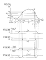
- - la Fig. 1 est un bloc-diagramme du système d'incrustation selon une première réalisation, dans lequel le circuit de commande de gain est détaillé ;
- - la Fig. 2 neutre, dans le système trichromatique R, V, B, les limitas des domaines colorimétriques relatives aux images d'avant scène et de fond, définissant le domaine trichromatique de transition;
- - Les Figs. 3A à 3E représentent différents signaux en vue d'élaborer un signal de commande de gain primaire à partir d'une composante primaire du signal vidéo de l'image composite d'avant-scène et de fond ; et
- - la Fig. 4 représente, sous la forme d'un bloc-diagramme, une seconde réalisation du système d'incrustation dans lequel le circuit de commande de gain est une partie de celui de la Fig. 1.
- - Fig. 1 is a block diagram of the overlay system according to a first embodiment, in which the gain control circuit is detailed;
- - Fig. 2 neutral, in the trichromatic system R, G, B, the limits of the colorimetric domains relating to the foreground and background images, defining the trichromatic domain of transition;
- - Figs. 3A to 3E represent different signals for the purpose of developing a primary gain control signal from a primary component of the video signal of the composite foreground and background image; and
- - Fig. 4 shows, in the form of a block diagram, a second embodiment of the overlay system in which the gain control circuit is a part of that of FIG. 1.
Le système d'incrustation d'images en télévision en cou- laurs tel que représenté à la Fig. 1 reçoit à ses entrées 1b et 1a deux signaux vidéo composites qui sont transmis respectivement partir d'une première source vidéo fournissant le signal composite d'une image de télévision en couleurs composite b et à seconde partir d'une/source vidéo fournissant le signal composite d'une image de-télévision en couleurs d'arrière-scène a. L.image b est par exemple celle représentant un personnage p évoluant devant un fond en couleurs f, et l'image a est par exemple un décors an couleurs à substituer au fond f. Le domaine colorométrique de l'image p est sensiblement le complément du domaine colorométrique de l'image f dans le système colorométrique total. Les première et seconde sources vidéo sont synchronisées et sont généralement des caméras couleurs électroniques mais peuvent être également d'autres sources vidéo qui sont utilisées couramment dans la technique du trucage vidéo, telles que des magnétoscopes, des transmetteurs de diapositives, etc.The color television picture-in-picture system as shown in FIG. 1 receives at its
On a représenté à la Fig. 2 le système cartésien trichromatique classique, relatif aux trois coordonnées monochrematiques des composantes primaires rouge R, verte V et bleue B d'un signal vidéo en couleurs Le domaine colorimétrique D du fond f est à l'intérieur d'un parallélépipède délimité par trois paires de plans parallèles définis par des premières tendions de référence et ayant pour équations VR = VR1 et VR = VR2, VV = VV1 et VV = VV2, VB = VB1 et VB = VB2. Le domaine colorimétrique D' de l'image p est à l'extérieur d'un parallélépipède délimité par trois paires de plans parallèles définis par des secondes tensions de référence et ayant pour équations VR = VR1 et VR = VR'2, VY = VV'1 et VV = VV'2, VB = VB'1 et VB = VB'2. Le domaine D est contenu dans le domaine D'. Les domaines D et D' sont séparés par un domaine dit de transition T dont les parties non recouvertes par le domaine D et projetées sur les plans de coordonnées VR =O, VV = O et VB = O sont hachurées dans la Fig. 2. Ce domaine de transition T correspond au mélange "flou" de couleurs des bords communs des images f et p ou, plus généralement, à des parties d'image "communes ou confondues" des images pet f. De telles parties d'images sont par exemple la chevelure ébrous- saillée d'un personnage ou un objet transparent, tel qu'un verre ou une bouteille, à travers lesquels apparaît le fond f. Dans le système d'incrustation en télévision en couleurs du brevet français précité N° 2.142.820 selon lequel la séparation des images p et f était abrupte au niveau des plans délimitant le domaine parallélépipédique D, l'image incrustée en couleurs résultante présentait lesdites parties communes avec ledit fond f. Ceci produisait un effet de bordure gênant et également une reproduction non fidèle du décors. Au contraire, conformément à l'objet de l'invention, le système de la Fig. 1 permet de supprimer ce défaut car, dans l'image incrustée en couleurs résultante r transmise par la sortie 2 du système, un verre de l'image p par exemple fait apparaître à travers celui-ci la partir du décors correspondante.There is shown in FIG. 2 the classical trichromatic Cartesian system, relating to the three monochrematic coordinates of the primary red R, green V and blue B components of a color video signal The colorimetric domain D of the background f is inside a parallelepiped delimited by three pairs of parallel planes defined by first reference trends and having for equations VR = VR 1 and VR = VR 2 , VV = VV 1 and VV = VV 2 , VB = VB 1 and VB = VB 2 . The colorimetric domain D 'of the image p is outside a parallelepiped delimited by three pairs of parallel planes defined by second reference voltages and having for equations VR = VR 1 and VR = VR' 2 , VY = VV ' 1 and VV = VV' 2 , VB = VB ' 1 and VB = VB' 2 . Domain D is contained in domain D '. The domains D and D 'are separated by a so-called transition domain T, the parts of which are not covered by the domain D and projected onto the coordinate planes VR = O, VV = O and VB = O are hatched in FIG. 2. This transition domain T corresponds to the “fuzzy” mixture of colors of the common edges of the images f and p or, more generally, to “common or confused” image parts of the pet images f. Such parts of images are for example the fluffy hair of a character or a transparent object, such as a glass or a bottle, through which the background appears f. In the color television inlay system of the aforementioned French patent No. 2,142,820 according to which the separation of the images p and f was abrupt at the level of the planes delimiting the parallelepipedic domain D, the resulting image inlaid in colors presented said parts common with said fund f. This produced an annoying border effect and also an unfair reproduction of the decor. On the contrary, in accordance with the object of the invention, the system of FIG. 1 makes it possible to eliminate this defect because, in the image inlaid in resulting colors r transmitted by the
On notera que les deux intervalles de tensions de référence du domaine de transition T relativement à chaque coordonnée colorométrique R, V, B, respectivement VR1 - VR'1 et VR'2 - VR2, VV1 - VV'1 et VV2 - VV2, VB1 - VB'1 et VB'2 - VB2 peuvent être différents et peuvent être sélectionnés indépendamment par l'opérateur, l'un par rapport à l'autre et chacun par rapport aux quatre autres des deux autres composantes primaires, comme on le verra dans la suite.It will be noted that the two reference voltage intervals of the transition domain T relative to each color coordinate R, G, B, respectively VR 1 - VR ' 1 and VR' 2 - VR 2 , VV 1 - VV ' 1 and VV2 - VV 2 , VB 1 - VB ' 1 and VB' 2 - VB 2 can be different and can be selected independently by the operator, one with respect to the other and each with respect to the other four of the other two primary components , as will be seen below.
Toujours en référence à la Fig. 2 et relativement aux systèmes d'incrustation antérieurs dit à fond bleu, on notera que pour ces systèmes le domaine du fond est un point de coordonnées VB, 0, O ou un segment ouvert colinéaire à l'axe de coordonnée VB, représentant les valeurs VB supérieures à VB1. Le domaine colorimétrique de l'image d'avant-scène, tel qu'un personnage, est défini par tous les points ayant leur composante primaire sélectionnée bleue telle que VB < VB1. Comme déjà dit, VH1 dépend d'une relation linéaire des deux autres composantes telles que VB1 = kR VR + KV VV, où KR et KV sont des paramètres réglables manuellement.Still with reference to FIG. 2 and relative to the earlier inlay systems said to have a blue background, it will be noted that for these systems the background domain is a point of coordinates VB, 0, O or an open segment collinear with the axis of coordinate VB, representing the values VB greater than VB 1 . The colorimetric domain of the foreground image, such as a character, is defined by all the points having their primary component selected blue such as VB <VB 1 . As already said, VH 1 depends on a linear relation of the two other components such as VB 1 = k R VR + K V VV, where K R and K V are manually adjustable parameters.
Selon l'exemple de réalisation montré à la Fig. 1, on a supposé que les entrées 1a et 1b recevaient directement les signaux vidéo composites de l'image d'arrière-scène et de l'image composite d'avant-scène et de fond b = p + f. Dans ce cas, le signal vidéo b est transmis à l'entrée d'un séparateur vidéo 3 qui filtre les trois composantes primaires bR, bY et bB de l'image b pour les transmettre aux trois entrées 40R, 40V, 40B d'un circuit de commande de gain 4. Cependant, selon d'autres réalisations dépendant du procédé de télévision en couleurs adopté, les images b et a peuvent être transmises à partir des première et seconde sources directement sous la forme de composantes primaires bR, bV, bB et aR, aV, aB ou d'une autre combinaison de celles-ci. Dans ce dernier cas, les composantes primaires sont transmises directement aux entrées 40R, 40V, 40B et des mélangeurs vidéo convenables restituent aux entrées 1a et 1b les signaux vidéo composites a et b.According to the exemplary embodiment shown in FIG. 1, it has been assumed that the
Les signaux vidéo composites a et b sont transmis respectivement aux entrées vidéo 50a, 50b d'amplificateurs à gain variable 5a, 5b. Les amplificateurs 5a et 5bont un gain maximal G et présentent une variation de gain respective α G et (1-α) G corrélé au signal de comznande α transmis par la sortie 44 du circuit 4. Ce signaler est un signal de tension analogique variant entre un premier niveau dit bas égal à zéro et un second niveau dit haut égal à l'unité. Ce signal α commande l'incrustation de la partie du signal vidéo b représentant l'image d'avant scène p dans le signal vidéo a en supprimant les effets de bord.The composite video signals a and b are transmitted respectively to the
Ce signal α est issu du produit analogique de signaux de commande de gain primaires αR, αV, αB, tels que celui αR représenté à la Fig. 3D qui est relatif uniquementàla détection des intervalles monochromatiques primaires rouges associés aux domaines D, D' et T et qui ne dépend donc pas des deux autres composantes primaires (bleue et verte) de l'image composite d'avant-scène et de fond. Le premier niveau dit bas du signal a correspond à la détection de points de l'image composite b appartenant au domaine colorimétrique D' de l'image p et le second niveau dit haut du signal α correspond à la détection de points de l'image b appartenant au domaine colorimétrique D de l'image f. Un niveau de tension intermédiaire du signal α compris entre le premier niveau dit bas et le second niveau dit haut correspond à la détection de points de l'image b appartenant au domaine colorométrique de transition T commun auximages p et f. Le niveau de tension intermédiaire représentatif d'un point image du domaine T-est égal au produit de un, deux ou trois rapports selon qu'une, deux ou trois coordonnées primaires du point sont comprises respectivement dans un intervalle de tensions de référence définissant deux plans parallèles et voisins des domaines parallélépipédiques D et D'. Chaque rapport est égal au rapport de la distance du point à la face parallèle associée du domaine D ou du domaine D'etde la distance entre les deux faces parallèles associées des domaines D et D'respectivement pour chaque coordonnée, ou peut être en général égal à une relation quasi-linéaire de ce rapport. Par exemple, pour un point du domaine T qui a une coordonnée rouge VRT et qui est comprise entre les plans définis par l'intervalle de tensions VR = VR'1 et VR = VR1, comme montré aux Figs. 2 et 3A, ledit produit de rapports est le produit :
- a) d'un premier rapport égal à (YRT- VR'1)/(YR1 - VR'1), si le point considéré a des secondes coordonnées verte et bleue VVT, VBT, comprises dans le domaine D entre les paires de plans respectives VV = VV1, VV = VV2 et VB = VB1, VB = VB2 ;
- b) dudit premier rapport et d'un second rapport égal à (VVT1 - VV'1)/(VV1-VV'1) ou à (VVT2- VV2)/(VV'2- VV2), si le point considér a une seconde coordonnée verte VVT1 ou VVT2 comprise entre les plans VV = VV1 et VV = VV1 ou les plans VV = VV2 et VV = VV'2 et a une troisième coordonnée bleue VBT comprise entre les plans VB = VB1 et VB = VB2 ;
- c) dudit premier rapport et d'un autre rapport égal à (VBT1-VB'1)/(VB1-VB'1) ou à (VBT2 - VB2)/(VB'2 - VB2) si le point considéré a une troisième coordonnée bleue VBT1 ou VBT2 comprise entre les plan VB = VB'1 et VB = VB1 ou entre les plans VB=VB2 et VB = VB'2 et a une seconde coordonnée verte VVT comprise entre les plans VV = VV1 et
VV = VV2 ; - d) dudit premier rapport, de l'un desdits seconds rapports définis à l'alinéa b) ou c) et d'un troisième rapport égalàl'un desdits seconds rapports définis à l'alinéa c) ou b), si le point considéré appartient aux quatre sous-domaines parallélépipédiques du domaine T entre les paires d'arêtes des domaines D et Dt, tels que montrés par les hachures croisées sur la Fig. 2.
- a) of a first ratio equal to (YR T - VR ' 1 ) / (YR 1 - VR' 1 ), if the point considered has second green and blue coordinates VV T , VB T , included in the domain D between the respective plane pairs VV = VV 1 , VV = VV 2 and VB = VB 1 , VB = VB 2 ;
- b) of said first gear and of a second gear equal to (VV T1 - VV ' 1 ) / (VV 1 -VV' 1 ) or to (VV T2 - VV 2 ) / (VV ' 2 - VV 2 ), if the point considered has a second green coordinate VV T1 or VV T2 between the planes VV = VV 1 and VV = VV 1 or the planes VV = VV 2 and VV = VV ' 2 and has a third blue coordinate VB T between the VB = VB 1 and VB = VB 2 planes;
- c ) of said first report and of another report equal to (VB T1 -VB ' 1 ) / (VB 1 -VB' 1 ) or to (VB T2 - VB 2 ) / (VB ' 2 - VB 2 ) if the point considered has a third blue coordinate VB T1 or VB T2 between the planes VB = VB ' 1 and VB = VB 1 or between the planes VB = VB 2 and V B = VB' 2 and has a second green coordinate VV T included between the planes VV = VV 1 and
VV = VV 2 ; - d) of said first report, of one of said second reports defined in paragraph b) or c) and of a third report equal to one of said second reports defined in paragraph c) or b), if the point considered belongs to the four parallelepipedal subdomains of the T domain between the pairs of edges of the D and D t domains, as shown by the cross hatching in FIG. 2.
Par contre, on notera que, si l'une des coordonnées d'un point du domaine colorométrique est plus grande que VR'2, VV'2 et VB'2 ou plus petite que VR'1, VV'1 et VB'1 respectivement, le point appartient au domaine D' de l'image d'avant-scène p et, par suite, correspond au niveau bas du signal α.On the other hand, it will be noted that, if one of the coordinates of a point of the colorometric domain is larger than VR ' 2 , VV' 2 and VB ' 2 or smaller than VR' 1 , VV ' 1 and VB' 1 respectively, the point belongs to the domain D 'of the proscenium image p and, consequently, corresponds to the low level of the signal α.
Comme montré à la Fig. 1, le signal α est transmis à partir de la sortie 44 directement à l'entrée de commande de gain 51a de l'amplificateur 5a et à l'entrée d'un circuit inverseur analogique 52b qui restitue le signal (1-α) à l'entrée de commande de gain 51b de l'amplificateur 5b. Lez sorties des amplificateurs 5a et 5b sont reliées aux deux entrées 6a et 6b d'un mélangeur vidéo classique 6 qui transmet à sa sortie 2 le signal vidéo de l'image incrustée résultante r. Ce signal r restitue, selon la relation : signal r = [α(signal a)+ (1-α) (signal b)] G :
- a) la zone de l'image d'arrière-scène a correspondant à celle du domaine-D de l'image de fond f, lorsque le signal α est au second niveau dit haut (α = 1) ;
- b) la zone de l'image b correspondant à celle du domaine D' de l'image d'avant-scène p, losque le signala est au premier niveau dit bas (α = 0) ;
- c) la zone de l'image commune aux images p et a appartenant au domaine colorométrique de transition T lorsque le signal α a un niveau intermédiaire compris entre les premier et second niveaux "0" et "1" avec une contribution prépondérante de l'image d'avant-scène p lorsque le niveau α est voisin du premier niveau "0" et une contribution prépondérante de l'image d'arrière-scène a lorsque le niveau de α est voisin du second niveau "1".
- a) the area of the backstage image a corresponding to that of the domain-D of the background image f, when the signal α is at the second level called high (α = 1);
- b) the area of image b corresponding to that of the domain D ′ of the proscenium image p, when the signal is at the first level known as low (α = 0);
- c) the zone of the image common to the images p and a belonging to the transition colorometric domain T when the signal α has an intermediate level comprised between the first and second levels "0" and "1" with a preponderant contribution of the foreground image p when the level α is close to the first level "0" and a preponderant contribution of the background image a when the level of α is close to the second level "1".
En se référant à nouveau aux Figso 1 et 3 , on décrit le circuit de commande de gain produisant le signal de commande de gain α. A chaque entrée 40R, 40V, 40B transmettant une composante primaire bR , bV, bB du signal vidéo b sont reliés en série un détecteur 41RI 41V, 41B qui détecte des intervalles colorimétriques primaires appartenant aux domàines D, D' et T et un circuit de multiplication analogique 42R, 42V, 42 B respectivement. Seuls, le détecteur 41R et le circuit de multiplication 42R sont détaillés sur la Fig. 1, les autres étant respectivement identiques, aux réglages près des tensions de référence limitant les intervalles colorimétriquesoReferring again to
Le détecteur 41R comprend deux amplificateurs opérationnels à gain variable 411 et 412 ayant respectivement leurs entrées inverse (-) et directe (+) reliées à la borne 40Ro Chaque amplificateur 411, 412 est un amplificateur non-linéaire, c'est-à-dire ayant un gain variant comme une fonction quasi-linéaire de la tension appliquée à son entrée dans une fenêtre d'admission déterminée par son gain et ayant une impédance de sortie faible. L'autre entrée, respectivement directe (+) et inverse (-), d'un amplificateur 411, 412 reçoit un signal de tension VR1, VR2,réglable au moyen d'un potentiomètre 413,414 et correspondant à l'une des limites de tension de référence de la primaire rouge du domaine D du fond f. Le réglage des potentiomètres 413 et 414 peut être commun pour une différence VIR2-VR1 constante prédéterminée. L'amplificateur 411 amplifie tout signal d'amplitude bR compris entre les premières limites VR1 et VR1 du domaine de transition T avec un gain g1 proportionnel à k1(bR- VR'1)/(VR1- VR'1), où k1 est une constante dépendant du réglage du gain de l'ampLificateur 411 et fonction de l'intervalle de tensions (VR1 -VR'1). De même, l'amplificateur 412 amplifie tout signal d'amplituda bR comprise entre les secondes limites VR2 et ![]()
![]()
![]()
![]()
![]()
![]()
![]()
![]()
![]()
![]()
![]()
![]()
![]()
![]()
![]()
![]()
La combinaison par multiplication analogique des signaux αR1 et αR2 en un signal de commande de gain primaire αR est réalisée dans un circuit 42R tel qu'une porte ET analogique classique qui comprend côté sortie un transistor 423 et côté entrée deux diodes 424, 425, comme montré à la Fig. 1, ou deux transistors montés en diodes. Les deux autres circuits de multiplication analogiques 42V et 42B restituent des signaux de commande de gain primaires αV et αB qui délimitent, de manière analogue au signal αR montré à la Fig. 3D, les intervalles monochromatiques vert et bleu associés aux domaines D, D' et T. La multiplication analogique des trois signaux αR. αV αB est effectuée par un circuit analogique 43 tel qu'une porte ET analogique classique. Ce circuit 43 comprend, côté de ses trois entrées, trois diodes 430R, 430V, 430B, qui recoivent respectivement les signaux αR, αV, αB, comme montré à 1a Fig. 1, ou trois transistors montés en diodes et, côté de sa sortie 44, un transistor 431. La sortie 44 du circuit 43 transmet le signal de commande de gain global α vers les amplificateurs à gain variable 5a et 5b.The combination by analog multiplication of the signals α R1 and α R2 into a primary gain control signal α R is carried out in a
Selon une seconde variante montrée à la Fig. 4, le système d'incrustation d'images de télévision en couleurs comprend, si nécessaire, le séparateur vidéo 3b et un séparateur vidéo 3a recevant le signal vidéo composite a, via l'entrée 1a. Les séparateurs vidéo 3a et 3b filtrent et séparent les composantes primaires aR, aV aB et bR, bV,bB des signaux vidéo a et b reçus. Les trois sorties du séparateur vidéo 3b transmettent respectivement les composantes primaires séparées bR, bV, bB aux trois entrées vidéo 50bR, 50bV, 50bB de trois premiers ampli- ficateurs à gain variable 5bR, 5bV, 5bB. Les trois sorties du séparateur vidéo 3a transmettent respectivement les composantes primaires séparées aR, aV, aB aux trois entrées vidéo 50aR, 50aV, 50aB de trois seconds amplificateurs à gain variable 5aR, 5aV, 5aB. Ces premiers et seconds amplificateurs sont analogues aux amplificateurs 5a et 5b de la Fig. 1 et ont un gain maximal égal à Go Les entrées 51bR, 51bV, 51bB des amplificateurs 5bR, 5bV, 5bB reçoivent chacune un second signal de commande de gain primaire inversé, respectivement (1-![]()
![]()
![]()
![]()
![]()
![]()
![]()
![]()
![]()
![]()
L'entrée du détecteur 45 est reliée à la borne 44 et reçoit le signal de commande de gain α. La sortie du détecteur 45 est reliée à des premières entrées des circuits analogiques ET 46R, 46V, 46B. Ce détecteur 45 est composé de bascules convenables ou d'un comparateur de tension. Il détecte la transition d'un niveau bas à un niveau intermédiaire du signala et inversement afin de transmettre un signal αD+T dont le premier niveau dit bas délimite le domaine D' de l'image d'avant-scène p, lorsque le signal α est au premier niveau dit bas, et dont le second niveau dit haut délimite l'ensemble des domaines D+T, lorsque le signal α est au second niveau dit haut ou à un niveau intermédiaire. Les secondes entrées des circuits analogiques ET 46R, 46v et 46B sont reliées respectivement aux sorties des circuits analogiques ET 42R, 42v, 42B qui transmettent les premiers signaux de commande de gain primaires αR, αV, αB. Chaque second signal commande gain signal de commande de gain primaire ![]()
![]()
![]()
![]()
![]()
![]()
Bien que l'invention ait été décrite selon deux exemples préférés de réalisation, d'autres variantes sensiblement similaires par des modifications de structure, notamment du circuit de commande de gain, peuvent être facilement imaginables par l'homme de l'art dans la cadre de l'invention définie par les revendicaticns annexées. La convention précédente, à savoir du premierniveau bas relatif à l'image d'avant-scène p et du second niveau haut relatif à l'image de fond f, peut être inversée. D'autre part, tout autre système de coordonnées colorimétriques se déduisant du système R, V, B par des relations linéaires peut être utilisé. Il est possible en particulier de se référer au système de coordonnées bien connues R-Y, B-Y, Y où Y est le signal de luminance d'un signal vidéo d'images en couleurs.Although the invention has been described according to two preferred embodiments, other variants which are substantially similar by structural modifications, in particular of the gain control circuit, can be easily imagined by those skilled in the art in the context of the invention defined by the appended claims. The previous convention, namely the first low level relating to the foreground image p and the second high level relative to the background image f, can be reversed. On the other hand, any other system of colorimetric coordinates deduced from the system R, G, B by linear relations can be used. It is in particular possible to refer to the well-known coordinate system RY, BY, Y where Y is the luminance signal of a video signal of color images.
Claims (8)
Applications Claiming Priority (2)
| Application Number | Priority Date | Filing Date | Title |
|---|---|---|---|
| FR7903521A FR2448821A1 (en) | 1979-02-12 | 1979-02-12 | METHOD AND SYSTEM FOR INTEGRATING COLOR TELEVISION IMAGES |
| FR7903521 | 1979-02-12 |
Publications (2)
| Publication Number | Publication Date |
|---|---|
| EP0014665A1 true EP0014665A1 (en) | 1980-08-20 |
| EP0014665B1 EP0014665B1 (en) | 1983-04-06 |
Family
ID=9221858
Family Applications (1)
| Application Number | Title | Priority Date | Filing Date |
|---|---|---|---|
| EP80400202A Expired EP0014665B1 (en) | 1979-02-12 | 1980-02-08 | Method and system for picture overlay in colour television |
Country Status (5)
| Country | Link |
|---|---|
| US (1) | US4292649A (en) |
| EP (1) | EP0014665B1 (en) |
| JP (1) | JPS55107390A (en) |
| DE (1) | DE3062568D1 (en) |
| FR (1) | FR2448821A1 (en) |
Cited By (5)
| Publication number | Priority date | Publication date | Assignee | Title |
|---|---|---|---|---|
| FR2527033A1 (en) * | 1982-05-17 | 1983-11-18 | Telediffusion Fse | COLOR TELEVISION IMAGE INCLUSIVE SYSTEM |
| FR2561476A1 (en) * | 1984-03-19 | 1985-09-20 | Production Creation Audiovisue | Device for inlaying colour television images. |
| GB2176671A (en) * | 1985-05-31 | 1986-12-31 | Electrocraft Consultants Limit | Separation overlay |
| EP0776136A1 (en) * | 1995-11-23 | 1997-05-28 | Thomson Broadcast Systems | Method and apparatus for calculating a chroma key of an object evolving on a coloured background |
| EP0776135A1 (en) * | 1995-11-23 | 1997-05-28 | Thomson Broadcast Systems | Method and apparatus for processing a signal consisting of an object evolving on a coloured background |
Families Citing this family (20)
| Publication number | Priority date | Publication date | Assignee | Title |
|---|---|---|---|---|
| US4403249A (en) * | 1978-02-21 | 1983-09-06 | Dr. Ing. Rudolf Hell Gmbh. | Apparatus for mixing image signals to obtain a printing master |
| US5216755A (en) * | 1980-12-04 | 1993-06-01 | Quantel Limited | Video image creation system which proportionally mixes previously created image pixel data with currently created data |
| US5289566A (en) * | 1980-12-04 | 1994-02-22 | Quantel, Ltd. | Video image creation |
| US4374395A (en) * | 1980-12-24 | 1983-02-15 | Texas Instruments Incorporated | Video system with picture information and logic signal multiplexing |
| US4393394A (en) * | 1981-08-17 | 1983-07-12 | Mccoy Reginald F H | Television image positioning and combining system |
| FR2531290A1 (en) * | 1982-07-30 | 1984-02-03 | Poirier Alain | VIDEOCOMMUNICATION NETWORK BETWEEN VISIOPHONIC TERMINALS AND A BANK OF IMAGES |
| JPS60123978A (en) * | 1983-12-08 | 1985-07-02 | Kubota Ltd | Chrominance signal separating device |
| GB8420890D0 (en) * | 1984-08-16 | 1984-09-19 | Quantel Ltd | Video editing systems |
| FR2576733B1 (en) * | 1985-01-28 | 1987-04-24 | Telediffusion Fse | IMAGE OVERPRINTING SYSTEM |
| US4698666A (en) * | 1985-07-12 | 1987-10-06 | The Grass Valley Group, Inc. | Video key glow and border generator |
| GB8629832D0 (en) * | 1986-12-13 | 1987-01-21 | Quantel Ltd | Video graphics systems |
| GB8928058D0 (en) * | 1989-12-12 | 1990-02-14 | Crosfield Electronics Ltd | Digital image generation |
| US7448063B2 (en) | 1991-11-25 | 2008-11-04 | Actv, Inc. | Digital interactive system for providing full interactivity with live programming events |
| US7079176B1 (en) | 1991-11-25 | 2006-07-18 | Actv, Inc. | Digital interactive system for providing full interactivity with live programming events |
| US5724091A (en) | 1991-11-25 | 1998-03-03 | Actv, Inc. | Compressed digital data interactive program system |
| US5537141A (en) * | 1994-04-15 | 1996-07-16 | Actv, Inc. | Distance learning system providing individual television participation, audio responses and memory for every student |
| US5632007A (en) * | 1994-09-23 | 1997-05-20 | Actv, Inc. | Interactive system and method for offering expert based interactive programs |
| US5682196A (en) * | 1995-06-22 | 1997-10-28 | Actv, Inc. | Three-dimensional (3D) video presentation system providing interactive 3D presentation with personalized audio responses for multiple viewers |
| US7305691B2 (en) | 2001-05-07 | 2007-12-04 | Actv, Inc. | System and method for providing targeted programming outside of the home |
| US7075899B2 (en) | 2002-05-21 | 2006-07-11 | Actv, Inc. | System and method for providing private in-band data to digital set-top boxes in a broadcast environment |
Citations (7)
| Publication number | Priority date | Publication date | Assignee | Title |
|---|---|---|---|---|
| FR2128156A1 (en) * | 1969-02-20 | 1972-10-20 | Ass Motion Picture Tv Prod | |
| US3778542A (en) * | 1970-11-30 | 1973-12-11 | Technicolor | Blue screen travelling matte system |
| DE2612042A1 (en) * | 1975-03-21 | 1976-12-02 | Sonex Int Corp | SLIDING VIDEO MAT DISC SYSTEM |
| US4007487A (en) * | 1975-09-25 | 1977-02-08 | The Association Of Motion Picture And Television Producers Inc. | Electronic composite photography with color control |
| FR2345030A1 (en) * | 1976-03-15 | 1977-10-14 | Tektronix Inc | APPARATUS AND METHOD FOR PRODUCING VIDEO EFFECTS, ESPECIALLY IN COLOR TELEVISION |
| DE2749154A1 (en) * | 1976-11-03 | 1978-05-24 | Vlahos Gottschalk Res | COMPREHENSIVE ELECTRONIC COMPOSITION SYSTEM |
| NL7710959A (en) * | 1977-10-06 | 1978-10-31 | Philips Nv | Chromatic key signal generator for colour TV - has switch=over circuit linking second video source via controlled amplifier linked to matrix circuit |
Family Cites Families (2)
| Publication number | Priority date | Publication date | Assignee | Title |
|---|---|---|---|---|
| FR2142820B1 (en) * | 1971-06-25 | 1975-04-18 | Ortf | |
| JPS5340417A (en) * | 1976-09-24 | 1978-04-13 | Mitsubishi Electric Corp | Change over valve |
-
1979
- 1979-02-12 FR FR7903521A patent/FR2448821A1/en active Granted
-
1980
- 1980-02-08 DE DE8080400202T patent/DE3062568D1/en not_active Expired
- 1980-02-08 EP EP80400202A patent/EP0014665B1/en not_active Expired
- 1980-02-12 JP JP1489680A patent/JPS55107390A/en active Granted
- 1980-02-14 US US06/121,779 patent/US4292649A/en not_active Expired - Lifetime
Patent Citations (7)
| Publication number | Priority date | Publication date | Assignee | Title |
|---|---|---|---|---|
| FR2128156A1 (en) * | 1969-02-20 | 1972-10-20 | Ass Motion Picture Tv Prod | |
| US3778542A (en) * | 1970-11-30 | 1973-12-11 | Technicolor | Blue screen travelling matte system |
| DE2612042A1 (en) * | 1975-03-21 | 1976-12-02 | Sonex Int Corp | SLIDING VIDEO MAT DISC SYSTEM |
| US4007487A (en) * | 1975-09-25 | 1977-02-08 | The Association Of Motion Picture And Television Producers Inc. | Electronic composite photography with color control |
| FR2345030A1 (en) * | 1976-03-15 | 1977-10-14 | Tektronix Inc | APPARATUS AND METHOD FOR PRODUCING VIDEO EFFECTS, ESPECIALLY IN COLOR TELEVISION |
| DE2749154A1 (en) * | 1976-11-03 | 1978-05-24 | Vlahos Gottschalk Res | COMPREHENSIVE ELECTRONIC COMPOSITION SYSTEM |
| NL7710959A (en) * | 1977-10-06 | 1978-10-31 | Philips Nv | Chromatic key signal generator for colour TV - has switch=over circuit linking second video source via controlled amplifier linked to matrix circuit |
Cited By (10)
| Publication number | Priority date | Publication date | Assignee | Title |
|---|---|---|---|---|
| FR2527033A1 (en) * | 1982-05-17 | 1983-11-18 | Telediffusion Fse | COLOR TELEVISION IMAGE INCLUSIVE SYSTEM |
| EP0097068A1 (en) * | 1982-05-17 | 1983-12-28 | Etablissement Public de Diffusion dit "Télédiffusion de France" | Colour television picture inlay system |
| FR2561476A1 (en) * | 1984-03-19 | 1985-09-20 | Production Creation Audiovisue | Device for inlaying colour television images. |
| GB2176671A (en) * | 1985-05-31 | 1986-12-31 | Electrocraft Consultants Limit | Separation overlay |
| EP0776136A1 (en) * | 1995-11-23 | 1997-05-28 | Thomson Broadcast Systems | Method and apparatus for calculating a chroma key of an object evolving on a coloured background |
| EP0776135A1 (en) * | 1995-11-23 | 1997-05-28 | Thomson Broadcast Systems | Method and apparatus for processing a signal consisting of an object evolving on a coloured background |
| FR2741769A1 (en) * | 1995-11-23 | 1997-05-30 | Thomson Broadcast Systems | PROCESS FOR PROCESSING THE SIGNAL CONSISTING OF AN EVOLUTION SUBJECT BEFORE A COLORFOUND BACKGROUND AND DEVICE USING THE SAME |
| FR2741770A1 (en) * | 1995-11-23 | 1997-05-30 | Thomson Broadcast Systems | METHOD FOR CALCULATING A CUTTING KEY OF AN EVOLVING SUBJECT IN FRONT OF A COLORFOUND BASE AND DEVICE USING THE SAME |
| US5903318A (en) * | 1995-11-23 | 1999-05-11 | Thomson Broadcast Systems | Device and method for determining a key for clipping a subject moving against a colored background |
| US5923381A (en) * | 1995-11-23 | 1999-07-13 | Thomson Broadcast Systems | Device and method for processing a signal with a subject moving against a colored background |
Also Published As
| Publication number | Publication date |
|---|---|
| DE3062568D1 (en) | 1983-05-11 |
| JPH0316839B2 (en) | 1991-03-06 |
| FR2448821A1 (en) | 1980-09-05 |
| US4292649A (en) | 1981-09-29 |
| JPS55107390A (en) | 1980-08-18 |
| EP0014665B1 (en) | 1983-04-06 |
| FR2448821B1 (en) | 1984-02-24 |
Similar Documents
| Publication | Publication Date | Title |
|---|---|---|
| EP0014665B1 (en) | Method and system for picture overlay in colour television | |
| CA2909554C (en) | Device for acquiring bimodal images | |
| EP0194166B1 (en) | Picture overlay system | |
| EP0097068B1 (en) | Colour television picture inlay system | |
| EP0542744B1 (en) | Self-adapted colour video image overlay device and method | |
| US4100569A (en) | Comprehensive electronic compositing system | |
| US5264944A (en) | Multi-function digital CCD camera | |
| FR2524235A1 (en) | SPACE TRANSFORMATION SYSTEM COMPRISING A SIGNAL SIGNAL GENERATOR | |
| FR2563680A1 (en) | METHOD AND APPARATUS FOR COMPOSING VIDEO SIGNALS OF COLOR IMAGES | |
| EP0067083B1 (en) | Television camera colour correction circuit for improved image perception | |
| EP0776135A1 (en) | Method and apparatus for processing a signal consisting of an object evolving on a coloured background | |
| FR2509547A1 (en) | FILTER CIRCUIT | |
| FR2519501A1 (en) | STEREOSCOPIC TELEVISION SYSTEM | |
| FR2473240A1 (en) | COLOR CAMERA COMPRISING A VERTICAL OPENING CORRECTION CIRCUIT | |
| CA1245342A (en) | Image contour correcting device and use of said device in a color television camera | |
| EP0240417B1 (en) | Device for mixing video signals | |
| FR2533394A1 (en) | COLOR TELEVISION CAMERA COMPRISING A SINGLE SHOOTING TUBE | |
| EP0285494A1 (en) | Background discolouration device for a colour television picture fade-in system | |
| US3745238A (en) | Signal processing system for multiple signal transmission | |
| FR2516334A1 (en) | COMPLETELY COMPATIBLE RELIEF TELEVISION METHOD IN TWO DIMENSIONS, WITHOUT ALTERATION OF COLORS, APPLICABLE TO STANDARD SECAM | |
| JPS6329344Y2 (en) | ||
| RU2112321C1 (en) | Device for retransmission of color tv signals | |
| JP2667496B2 (en) | Color television transmission luminance signal correction circuit | |
| FR2608342A1 (en) | Method and system for automatic control of the saturation level of at least one of the R, G and B colour video signals | |
| JPS6033029B2 (en) | Electronic video image synthesis device |
Legal Events
| Date | Code | Title | Description |
|---|---|---|---|
| PUAI | Public reference made under article 153(3) epc to a published international application that has entered the european phase |
Free format text: ORIGINAL CODE: 0009012 |
|
| AK | Designated contracting states |
Designated state(s): BE CH DE GB IT NL SE |
|
| 17P | Request for examination filed |
Effective date: 19800930 |
|
| ITF | It: translation for a ep patent filed |
Owner name: ING. PIOVESANA PAOLO |
|
| GRAA | (expected) grant |
Free format text: ORIGINAL CODE: 0009210 |
|
| AK | Designated contracting states |
Designated state(s): BE CH DE GB IT NL SE |
|
| REF | Corresponds to: |
Ref document number: 3062568 Country of ref document: DE Date of ref document: 19830511 |
|
| PGFP | Annual fee paid to national office [announced via postgrant information from national office to epo] |
Ref country code: SE Payment date: 19840331 Year of fee payment: 5 |
|
| PGFP | Annual fee paid to national office [announced via postgrant information from national office to epo] |
Ref country code: DE Payment date: 19850219 Year of fee payment: 6 |
|
| PGFP | Annual fee paid to national office [announced via postgrant information from national office to epo] |
Ref country code: NL Payment date: 19870228 Year of fee payment: 8 |
|
| PGFP | Annual fee paid to national office [announced via postgrant information from national office to epo] |
Ref country code: CH Payment date: 19890207 Year of fee payment: 10 |
|
| PG25 | Lapsed in a contracting state [announced via postgrant information from national office to epo] |
Ref country code: SE Effective date: 19890209 |
|
| PGFP | Annual fee paid to national office [announced via postgrant information from national office to epo] |
Ref country code: GB Payment date: 19890228 Year of fee payment: 10 |
|
| PGFP | Annual fee paid to national office [announced via postgrant information from national office to epo] |
Ref country code: BE Payment date: 19890303 Year of fee payment: 10 |
|
| PG25 | Lapsed in a contracting state [announced via postgrant information from national office to epo] |
Ref country code: NL Effective date: 19890901 |
|
| NLV4 | Nl: lapsed or anulled due to non-payment of the annual fee | ||
| PG25 | Lapsed in a contracting state [announced via postgrant information from national office to epo] |
Ref country code: DE Effective date: 19891101 |
|
| PG25 | Lapsed in a contracting state [announced via postgrant information from national office to epo] |
Ref country code: GB Effective date: 19900208 |
|
| ITTA | It: last paid annual fee | ||
| PG25 | Lapsed in a contracting state [announced via postgrant information from national office to epo] |
Ref country code: CH Effective date: 19900228 Ref country code: BE Effective date: 19900228 |
|
| BERE | Be: lapsed |
Owner name: ETS PUBLIC TELEDIFFUSION DE FRANCE Effective date: 19900228 |
|
| GBPC | Gb: european patent ceased through non-payment of renewal fee | ||
| REG | Reference to a national code |
Ref country code: CH Ref legal event code: PL |
|
| EUG | Se: european patent has lapsed |
Ref document number: 80400202.0 Effective date: 19900118 |
|
| PLBE | No opposition filed within time limit |
Free format text: ORIGINAL CODE: 0009261 |
|
| STAA | Information on the status of an ep patent application or granted ep patent |
Free format text: STATUS: NO OPPOSITION FILED WITHIN TIME LIMIT |