EP0014006B1 - Automatische, mehrfach federbetätigte Injektionsvorrichtung - Google Patents
Automatische, mehrfach federbetätigte Injektionsvorrichtung Download PDFInfo
- Publication number
- EP0014006B1 EP0014006B1 EP80200016A EP80200016A EP0014006B1 EP 0014006 B1 EP0014006 B1 EP 0014006B1 EP 80200016 A EP80200016 A EP 80200016A EP 80200016 A EP80200016 A EP 80200016A EP 0014006 B1 EP0014006 B1 EP 0014006B1
- Authority
- EP
- European Patent Office
- Prior art keywords
- actuation
- injection
- spring
- outer housing
- container
- Prior art date
- Legal status (The legal status is an assumption and is not a legal conclusion. Google has not performed a legal analysis and makes no representation as to the accuracy of the status listed.)
- Expired
Links
Images


Classifications
-
- A—HUMAN NECESSITIES
- A61—MEDICAL OR VETERINARY SCIENCE; HYGIENE
- A61M—DEVICES FOR INTRODUCING MEDIA INTO, OR ONTO, THE BODY; DEVICES FOR TRANSDUCING BODY MEDIA OR FOR TAKING MEDIA FROM THE BODY; DEVICES FOR PRODUCING OR ENDING SLEEP OR STUPOR
- A61M5/00—Devices for bringing media into the body in a subcutaneous, intra-vascular or intramuscular way; Accessories therefor, e.g. filling or cleaning devices, arm-rests
- A61M5/178—Syringes
- A61M5/20—Automatic syringes, e.g. with automatically actuated piston rod, with automatic needle injection, filling automatically
- A61M5/2033—Spring-loaded one-shot injectors with or without automatic needle insertion
-
- A—HUMAN NECESSITIES
- A61—MEDICAL OR VETERINARY SCIENCE; HYGIENE
- A61M—DEVICES FOR INTRODUCING MEDIA INTO, OR ONTO, THE BODY; DEVICES FOR TRANSDUCING BODY MEDIA OR FOR TAKING MEDIA FROM THE BODY; DEVICES FOR PRODUCING OR ENDING SLEEP OR STUPOR
- A61M5/00—Devices for bringing media into the body in a subcutaneous, intra-vascular or intramuscular way; Accessories therefor, e.g. filling or cleaning devices, arm-rests
- A61M5/178—Syringes
- A61M5/20—Automatic syringes, e.g. with automatically actuated piston rod, with automatic needle injection, filling automatically
- A61M5/2066—Automatic syringes, e.g. with automatically actuated piston rod, with automatic needle injection, filling automatically comprising means for injection of two or more media, e.g. by mixing
-
- A—HUMAN NECESSITIES
- A61—MEDICAL OR VETERINARY SCIENCE; HYGIENE
- A61M—DEVICES FOR INTRODUCING MEDIA INTO, OR ONTO, THE BODY; DEVICES FOR TRANSDUCING BODY MEDIA OR FOR TAKING MEDIA FROM THE BODY; DEVICES FOR PRODUCING OR ENDING SLEEP OR STUPOR
- A61M5/00—Devices for bringing media into the body in a subcutaneous, intra-vascular or intramuscular way; Accessories therefor, e.g. filling or cleaning devices, arm-rests
- A61M5/178—Syringes
- A61M5/20—Automatic syringes, e.g. with automatically actuated piston rod, with automatic needle injection, filling automatically
- A61M2005/206—With automatic needle insertion
-
- A—HUMAN NECESSITIES
- A61—MEDICAL OR VETERINARY SCIENCE; HYGIENE
- A61M—DEVICES FOR INTRODUCING MEDIA INTO, OR ONTO, THE BODY; DEVICES FOR TRANSDUCING BODY MEDIA OR FOR TAKING MEDIA FROM THE BODY; DEVICES FOR PRODUCING OR ENDING SLEEP OR STUPOR
- A61M5/00—Devices for bringing media into the body in a subcutaneous, intra-vascular or intramuscular way; Accessories therefor, e.g. filling or cleaning devices, arm-rests
- A61M5/178—Syringes
- A61M5/20—Automatic syringes, e.g. with automatically actuated piston rod, with automatic needle injection, filling automatically
- A61M2005/2073—Automatic syringes, e.g. with automatically actuated piston rod, with automatic needle injection, filling automatically preventing premature release, e.g. by making use of a safety lock
-
- A—HUMAN NECESSITIES
- A61—MEDICAL OR VETERINARY SCIENCE; HYGIENE
- A61M—DEVICES FOR INTRODUCING MEDIA INTO, OR ONTO, THE BODY; DEVICES FOR TRANSDUCING BODY MEDIA OR FOR TAKING MEDIA FROM THE BODY; DEVICES FOR PRODUCING OR ENDING SLEEP OR STUPOR
- A61M5/00—Devices for bringing media into the body in a subcutaneous, intra-vascular or intramuscular way; Accessories therefor, e.g. filling or cleaning devices, arm-rests
- A61M5/178—Syringes
- A61M5/31—Details
- A61M2005/3103—Leak prevention means for distal end of syringes, i.e. syringe end for mounting a needle
- A61M2005/3107—Leak prevention means for distal end of syringes, i.e. syringe end for mounting a needle for needles
- A61M2005/3109—Caps sealing the needle bore by use of, e.g. air-hardening adhesive, elastomer or epoxy resin
-
- A—HUMAN NECESSITIES
- A61—MEDICAL OR VETERINARY SCIENCE; HYGIENE
- A61M—DEVICES FOR INTRODUCING MEDIA INTO, OR ONTO, THE BODY; DEVICES FOR TRANSDUCING BODY MEDIA OR FOR TAKING MEDIA FROM THE BODY; DEVICES FOR PRODUCING OR ENDING SLEEP OR STUPOR
- A61M5/00—Devices for bringing media into the body in a subcutaneous, intra-vascular or intramuscular way; Accessories therefor, e.g. filling or cleaning devices, arm-rests
- A61M5/178—Syringes
- A61M5/19—Syringes having more than one chamber, e.g. including a manifold coupling two parallelly aligned syringes through separate channels to a common discharge assembly
-
- A—HUMAN NECESSITIES
- A61—MEDICAL OR VETERINARY SCIENCE; HYGIENE
- A61M—DEVICES FOR INTRODUCING MEDIA INTO, OR ONTO, THE BODY; DEVICES FOR TRANSDUCING BODY MEDIA OR FOR TAKING MEDIA FROM THE BODY; DEVICES FOR PRODUCING OR ENDING SLEEP OR STUPOR
- A61M5/00—Devices for bringing media into the body in a subcutaneous, intra-vascular or intramuscular way; Accessories therefor, e.g. filling or cleaning devices, arm-rests
- A61M5/178—Syringes
- A61M5/31—Details
- A61M5/32—Needles; Details of needles pertaining to their connection with syringe or hub; Accessories for bringing the needle into, or holding the needle on, the body; Devices for protection of needles
- A61M5/3295—Multiple needle devices, e.g. a plurality of needles arranged coaxially or in parallel
- A61M5/3298—Needles arranged in parallel
Definitions
- the invention relates to an automatic, plural spring actuated, injecting device for substantially simultaneous injection of a plurality of injection liquids which are not allowed to be in prolonged contact with each other.
- the stressed spring is controlled by a releasing mechanism which, when actuated, serves to release the stressed spring, thereby releasing a force sufficient to move the hypodermic needle outwardly and the medicament dosage outwardly through the needle.
- a safety device is provided for preventing an unwanted actuation of the spring releasing mechanism, thus insuring that actuation will take place only after a deliberate actuating procedure has been accomplished including an appropriate interengagement of the device with the muscle tissue to be injected.
- actuation of the single spring is made to take place as the final part of a two spring sequential movement, the first part of which commences as a result of a single actuation of a single actuating mechanism and functions to initially move the needle or needles into the user.
- an automatic injecting device comprising 1) an outer housing wherein is accomodated an injection unit, comprising a cartridge and a discharge mechanism, the cartridge comprising a cylindrical liquid container, a hypodermic needle in operative association with the container and a plunger extending into the container, and the discharge mechanism comprising spring means operatively associated with the plunger and releasable means normally retaining the spring means in a stressed condition but operable upon actuation to effect release of the spring means, and 2) safety means to prevent unintentional actuation of the releasable means.
- Such an injecting device destined for self-injecting one single medicament or injection liquid, is known from US-A-4,031,893.
- US-A-3,016,897 relates to injection means for injecting serum, vaccine, virus and the like into animals.
- This known device is adapted to enable the substantially simultaneous injection of two injection liquids, if desired, by actuation of a single member held in one hand of the operator.
- the automatic injection device of the invention comprises within the outer housing at least two injection units, while by the spring force of one injection unit released first the releasable means of the other injection unit(s) is (are) also actuated at the discretion of the user.
- this mechanical interconnection is realized in three manners, viz.
- the present invention provides a plural injection unit device, in which one of the injection units can be quite simply bodily replaced in the event that a new and better ingredient is developed. Since each injection unit is provided with its own spring force and releasing mechanism, the remaining injection units will be left with properly sized springs and properly sized releasing mechanisms, and additional springs and releasing mechanisms can be properly sized for the new ingredients.
- Benactazine By maintaining the Benactazine in a separate container within the outer housing of a plural dosage device in association with its own hypodermic needle, its own stressed spring, its own releasing mechanism and its own safety, it becomes readily possible to retrofit such a unit in the event that a more effective ingredient should be subsequently developed. Moreover, by providing this capability it may be desirable in some situations to withhold the Benactazine while shooting the other drugs, which can be readily accomplished simply by leaving in the safety for the Benactazine.
- the present invention has particular advantages in connection with devices used to contain chemical warfare antidotes, the invention has general applicability and makes it possible to store a plurality of drugs in a separate environment which is most compatible with their individual shelf lives. Moreover, the invention enables the selection of the most advantageous concentration for the drug, that is, the volume in which the drug is dissolved which is known to favor its stability and influences the rate of absorption after injection into the body. In regard to the absorption rate, it is known that one can, in general, increase the rate of absorption by using a lower volume for any given amount of drug injected. This has been demonstrated to be the case in many instances. Thus, by following the principles of the present invention, it becomes possible to make plural injections of the same drug instead of one, and having, therefore, a smaller volume of injectate at each injection site which can demonstrably favorably influence the rate of absorption.
- a further advantage is that by the use of a plural dosage device which simultaneously makes plural injections, a larger volume of any given injectate can be given without causing discomfort and also creating a situation in the tissues that would favor rapid absorption. That is, one can comfortably anticipate that if two injections of 3 ml each were made in different sites, the rate of absorption of the injected drug would be more rapid than if the drug in an amount of 6 ml were injected into a single site. In addition, two injections of 3 ml of a given drug in different sites will produce less pain and discomfort to the patient than 6 ml injected into a single site.
- a further consideration is that when one injects large volumes, pressure is built up in the tissue as a result of the injection of higher volumes, which tends to promote loss of the injectate from the tissues through the needle track.
- pressure build-up at these two separate sites will be less than that pressure build-up created by a single injection of 6 ml in one site.
- the device 110 includes an outer housing assembly 111 in the form of two separate outer housing halves 112 and 113 molded of a suitable moldable material such as plastic.
- the housing halves when disposed together, provide a chamber suitable to receive therein first and second cartridge sub-assemblies and respective first and second power pack sub-assemblies, each of which is constructed in a manner similar to the first cartridge sub-assembly and first power pack sub-assembly described in detail below.
- the two housing halves 112 and 113 are arranged to be rigidly secured together in operative relation with respect to the sub-assemblies as aforesaid by a plurality of spacer rivets 114 which serve not only to rigidly secure the two housing halves together in operative relation but to retain the first and second sub-assemblies within the outer housing assembly in operative spaced relation.
- the mounting means of the plural injecting device 110 which serves to accomplish the actuation of the second releasing mechanism 194 as a result of the actuation of the first releasing mechanism 148 includes the provision of peripheral inwardly turned flanges 115 on the forward ends of the housing halves 112 and 113 which function in a manner described below and peripheral grooves 119 and 116 in the rearward interior of the housing halves 112 and 113 which function in a manner also described below.
- the mounting means includes a sliding block 117 which is mounted within the central rearward portion of the outer housing assembly 111 for longitudinal sliding movement between the housing halves 112 and 113.
- the block includes a pair of oppositely outwardly facing grooves 118, a first one of which is adapted to receive therein the adjacent portion of the annular flange 168 on the first inner tube 150.
- the other groove 118 receives therein the adjacent portion of the annular flange on the second inner tube 196.
- a first container support 120 in the form of a tubular member includes a forwardly extending nose portion 122 of an exterior cylindrical configuration sufficient to extend through the flanges 115.
- the exterior transition between the nose portion 122 and the remainder of the tubular member 120 provides an annular shoulder 124 which is adapted to normally engage the flanges 115.
- Slidably mounted within the tubular member 120 is a first glass ampule or dosage container 126.
- the container is formed of glass, generally in the form of a necked bottomless bottle.
- Fixed to the necked end of the container 126 is a cap assembly 128 carrying a longitudinally forwardly extending hypodermic needle.
- the exterior of the hypodermic needle 130 is covered by a shock absorbing resilient sheath 132 in accordance with the teachings contained in US patent 3,882,863, the disclosure of which is hereby incorporated by reference into the present specification.
- the cap assembly 128 provides an interior resilient diaphragm (not shown) constructed in accordance with the teachings contained in US-A-3,391,695, the disclosure of which is hereby incorporated by reference into the present specification.
- the diaphragm serves to seal the metallic material which forms the hypodermic needle 130 from the interior of the container 126 which has therein an appropriate liquid medicament dosage, indicated by the numeral 134.
- the end of the container opposite from the cap assembly 128 is closed by a plunger member 136 which, as shown, is in the form of a piston of resilient material formed to provide an interior rearwardly facing socket 138.
- the medicament dosage 134 is of a volume somewhat less than the total capacity of the container 126 and consequently plunger 136 is shown disposed in spaced relation within the opposite end of the container 126.
- a spacer member 140 is mounted in the end of the container and has a pronged forward portion 142 engaged within the socket 138 and a socket portion 144 formed in the rear portion thereof.
- the spacer member 140 thus forms a part of the plunger means which serves to move the liquid medicament 134 outwardly through the hypodermic needle after the diaphragm has been ruptured through hydraulic pressure. It will be understood that the dosage amount can be varied by varying the longitudinal size of the spacer member 140 or by eliminating the spacer member entirely when a maximum volume dosage is desired.
- a power pack sub-assembly which includes a first coil spring 146 retained in stressed condition by a first releasing mechanism, generally indicated at 148.
- the releasing mechanism includes an inner tube or sleeve 150 having an interior cylindrical periphery of a size sufficient to receive the spring 146 therein.
- a radially inwardly extending flange 152 At one end of the sleeve 150 is a radially inwardly extending flange 152 which serves to abuttingly receive one end of the stressed spring 146.
- the opposite end of the stressed spring 146 extends outwardly from the opposite end of the inner tube or sleeve 150 and is engaged by a pair of outwardly extending tabs 154 formed on one end portion of an elongated member 156 in the form of a metallic plate.
- the end of the elongated member 156 adjacent the tabs 154 is formed with a tongue 1 58 of a size to engage within the socket 144 in the end of spacer 140.
- the elongated member extends rearwardly from the tabs 154 through the interior of the spring 146 and has formed on the opposite rearward end thereof a pair of spring fingers 160 having forwardly facing locking shoulders 162 formed on the exterior thereof and rearwardly and inwardly inclined cam releasing surfaces 164 on the rearward extremities thereof.
- the locking shoulders 162 are adapted to engage a suitable locking disk 166 engaged with the rearward surface of the flange 152 of the inner tube.
- the forward end of the inner tube 150 is formed with a radially outwardly extending annular flange 168 which is spaced from the forward end of an outer tube 170 forming a part of the releasing mechanism 148.
- the outer tube 170 is slidably mounted over the exterior periphery of the inner tube and has at its rearward end a centrally apertured end wall 172 having forwardly and outwardly inclined cam surfaces 174 formed on the central portion thereof disposed in engagement with the inclined cam surfaces 164 on the spring fingers 160.
- the exterior periphery of the outer tube 170 is formed with annular projection or ridge 175 adapted to engage within the associated annular groove 119.
- the container support member 120, container 126, cap 128, needle 130, sheath 132, plunger 136 and spacer 140 constitute a first dosage cartridge sub-assembly and the spring 146, inner tube 150, elongated member 156, outer tube 170 and locking disk 166 constitute a first power pack sub-assembly for operating the cartridge sub-assembly.
- the plural dosage injecting device 110 includes a second cartridge sub-assembly similar to the first which includes a second container support member 176, a second container 178, second dosage 180, second cap 182, second needle 184, second sheath 186, second plunger 188 and second spacer 190; and second power pack sub-assembly similar to the first including second spring 192, second releasing mechanism 194, second inner tube 196, second elongated member 198, second locking disk and second outer tube 100.
- the plural injecting device 110 includes a safety mechanism which, as shown, is in the form of a single molded safety cap 202 which fits over the rearwardly protruding ends of both the first outer tube 170 and the second outer tube 100.
- the safety cap member 202 includes a first safety plug 204 which in its operative position extends between the first spring finger 160 of the first elongated member 156 to prevent inward movement thereof and a second safety plug 206 which cooperates in a similar fashion with the spring fingers of the second elongated member 198.
- the plural injecting device 110 has the characteristic that not only will the second dosage be substantially simultaneously injected as a result of the injection of the first, but the reverse operation is likewise insured, namely, the first dosage 134 will be substantially simultaneously injected as a result of the injection of the second dosage 180 in the event that the second releasing mechanism 194 is initially actuated, rather than the first releasing mechanism 148.
- the operation of the plural injecting device 110 will be described in relation to an operation in which the first releasing mechanism 148 is actuated initially, it being understood that the device will function in a reverse manner when the second releasing mechanism 194 is the first to be actuated.
- the user When the user desires to use the multiple injecting device 110, the user first removes safety cap 202. The user then manually grips the exterior of the outer housing assembly 111 and positions the nose pieces of the first and second container support members 120 and 172 into engagement with the area where the injection is to be made as, for example, the thigh. The user then applies an inward movement to the outer housing assembly 111 which has the effect of relatively moving the first and second cartridge sub-assemblies together with the first and second elongated members 156 and 198 respectively rearwardly.
- the nose portion 122 of the first container support member 120 serves as the actuating means of the first cartridge sub-assembly, the actuating stroke thereof constituting the amount of rearward movement of the member 120 required to effect disengagement of the locking shoulders 162 with the locking disk 166 as aforesaid.
- the inward movement of the spring fingers 160 during which this disengagement takes place constitutes the releasing stroke of the releasing mechanism 148.
- the stressed condition of the spring 146 is released which has the effect of moving rearwardly the first inner tube 150 and of moving forwardly the first elongated member 156 which, in turn, effects a forward movement of the entire first cartridge sub-assembly.
- the rearward movement of the relatively small mass represented by the inner tube 150 is stopped by engagement with the end wall 172 of the outer tube 170.
- the slide block 117 serves to mechanically interconnect the first inner tube 150 with the second inner tube 196 so that the rearward movement of the first inner tube 150 occasioned as a result of the actuation of the first reieasing mechanism 148 will be mechanically transmitted to the second inner tube 196, thus mechanically providing sufficient relative movement between the second inner tube 196 and the second outer tube 200 to insure movement of the second releasing mechanism through a releasing stroke greater than the releasing stroke of the first releasing mechanism.
- first inner tube 150 will have an initial rearward movement as the first releasing mechanism moves through its releasing stroke and a final shorter rearward movement as the first spring is released, both of which are transmitted to the second outer tube to positively insure sufficient rearward movement thereof to accomplish its releasing stroke even though the length of its releasing stroke exceeds slightly the length of the releasing stroke of the first inner tube.
- the forward movement of the first needle 130, the first cap 128, the first container 126, the first dosage 134, the first plunger 136 and the first spacer 140 will continue after the forward movement of the first support member 120 has been stopped until needle 130 reaches a fully extended position within the user's muscle tissue. After this position is reached, which is determined by the compression of the shock absorbing sleeve 132, the forward movement of the plunger 136 and spacer 140 will continue under the action of the spring 146 which has the effect of initially bursting the diaphragm seal and then moving the dosage 134 through the needle 130 into the muscle tissue of the user. Forward movement is arrested when the plunger 136 reaches the full extent of its movement within the container 126.
- the second dosage 180 is injected in a similar manner by the forward movement of the second elongated member 198 under the action of the second spring 192 after the forward movement of the second container support member 176 has been arrested and the second needle 184 has been moved to its extended position.
- the safety means 202 into two separate cap pieces, one of which contains the first safety plug 204 and the other of which contains the second safety plug 206. Where two separate cap pieces are provided, the user will have the option of achieving the aforesaid generally simultaneous injection of both dosages by removing both cap pieces, or of injecting only one of the dosages by removing only the safety cap piece associated with that dosage.
- the plural injecting device 210 is similar to the plural injecting device 110 previously described, in that it includes first and second cartridge sub-assemblies operated by first and second power pack sub-assemblies, each cooperating pair of sub-assemblies being constructed similar to the pair of cooperating sub-assemblies described in detail in connection with the plural injecting device 110.
- the plural injecting device 210 includes an outer housing assembly 211 which is similar to the outer housing assembly 111 previously described, in that it is made up of two cooperative halves 212 and 213 held together by appropriate suitable fastening means, such as rivets 214.
- the forward end of the outer housing halves 212 and 213 includes inwardly directed peripheral flanges 215 which are constructed similar to the flanges 115 and perform similar functions.
- the plural injecting device 210 differs from the plural injecting device 110 in that, rather than providing peripheral grooves 116, the housing halves are extended rearwardly to receive therein a lever 216.
- Lever 216 has its central portion pivoted to the outer housing assembly 211 by a pivot pin 217 extending between the housing halves 212 and 213.
- the outer ends of the lever 216 are bifurcated, as indicated at 218 and 219, so as to receive therebetween safety plugs 304 and 306 respectively forming a part of separate safety caps 302 and 302'.
- the operation of the plural injecting device 210 is similar to the plural injecting device 110 in that the mounting means for the two pairs of sub-assemblies is such that whichever one of the cooperating pairs of sub-assemblies is initially actuated, the mounting means will be operable to insure that as a result of such actuation the releasing mechanism of the other pair of cooperating sub-assemblies will be actuated.
- the arrangement is capable of selective operation and it is for this reason that separate cap members are illustrated, although again it will be understood that a single safety cap such as the safety cap 202 may be provided if desired.
- the operation of the plural injecting device 210 will be described in relation to a user manipulation in which the first releasing means 248 is initially actuated.
- safety caps 302 and 302' are first removed.
- initial actuation is accomplished by the user manually gripping the exterior of the outer housing 211 and moving the same toward the muscle area where injection is to take place.
- nose piece 222 of the first container support member 220 will engage the skin of the user together with the nose piece of the second support member 276.
- the first and second cartridge sub-assemblies are thus moved rearwardly within the housing assembly 211 carrying therewith first and second elongated members 256 and 298.
- first outer tube 270 and second outer tube 300 with respect to the outer housing are resisted by virtue of the engagement of the bifurcated ends 218 and 219 of the lever 216 therewith.
- the relative movement which thus occurs between the first elongated member 256 and first outer tube 270 causes cam surfaces 264 to move relative to the cam surfaces 274, thereby moving spring fingers 260 inwardly toward one another until locking shoulders 262 move out of engagement with the locking ring 266.
- the releasing mechanism 248 is thus actuated, releasing the first stressed spring 246 which initially causes the inner tube 250 to move rearwardly until the rear end thereof engages the end 272 of the outer tube 270.
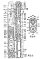
- the plural injecting device 310 is similar to the plural injecting devices 110 and 210 previously described to the extent that it includes a first cartridge sub-assembly and cooperating first power pack sub-assembly constructed in the manner described above in detail in connection with the plural injecting device 110.
- the plural injecting device 310 includes a second automatic injecting unit or assembly, generally indicated at 376, which is constructed in accordance with the teachings contained in US patent 2,832,339, the disclosure of which is hereby incorporated by reference into the present specification.
- the unit 376 includes a tubular dosage container support member 378, the forward portion of which is formed with a counterbore for receiving therein a cylindrical dosage container 380.
- the forward end of the container is closed by a stopper or plug 382 of suitable rubber or plastic material.
- Plug 382 is retained in closing relation with the forward end of the container 380 by an end cap member 384 of molded plastic material.
- the cap is retained on the container support member 378 by interengagement of an annular ridge 386 formed on the exterior periphery of the tubular member 378 with an annular groove 388 formed on the interior periphery of the cap member 384.
- the rearward end of the dosage container 380 is closed by a plunger 390 which is slidably sealingly engaged within the rearward end thereof so as to enclose within the container a dosage 392 of a liquid medicament.
- a hypodermic needle 394 is disposed within the container 380 and has its pointed end disposed within a recess formed in the plug 382.
- a disk 396 of plastic is disposed within the forward end of the container 380 in surrounding sealed relation with the hypodermic needle 394 and in abutting engagement with the plug 382. The disk serves to releasably hold the needle in its storage position and to provide peripheral sealing therefor during the dosage injecting stroke of the plunger 390.
- the opposite end of the hypodermic needle 394 is enlarged as indicated at 398, for engagement by the plunger and provides radially extending grooves for communicating the dosage 392 with the hollow interior of the hypodermic needle 394 when the plunger 390 is in engagement therewith.
- the rearward end portion of the container support member 378 constitutes an inner tube portion 400 which forms a part of a releasing mechanism, generally indicated at 402, similar to the releasing mechanisms previously described.
- the releasing mechanism 402 also includes an outer tube 404 which is slidably mounted over the inner tube portion 400 for limited reciprocating movement as determined by an annular ridge 406 formed on the exterior periphery of the tubular container support member 378 at a position spaced rearwardly from the annular ridge 386.
- the annular ridge 406 is adapted to engage within an elongated annular groove 408 formed on the interior periphery of the outer tube 404.
- the releasing mechanism also includes an elongated member 410 which is disposed within the inner tube portion 400 and has its forward end disposed in abutment with the plunger 390.
- the forward end of the elongated member 410 is also configured to engage the forward end of a stressed coil spring 412 which surrounds the central portion of the elongated member within the inner tube portion 400 and has its rearward end engaged with an apertured end wall 414 formed on the rearward end of the inner tube portion 400.
- the rearward end of the elongated member 410 is formed with a pair of laterally spaced laterally movable spring fingers 416, the rearward extremities of which are formed with rearwardly and inwardly inclined cam surfaces 418. Extending inwardly from the forward ends of the cam surfaces 418 is a pair of locking shoulders 420 adapted to engage a locking disc 422 seated on the rear centrally apertured wall 414 of the inner tube portion 400.
- the outer tube 404 includes a rearward end wall 424 formed with cam surfaces 426 which are disposed in engagement with the cam surfaces 418 so as to effect a laterally inward movement of the spring fingers toward one another to disengage locking shoulders 420 from locking ring 422 in response to either a relative rearward movement of the inner tube portion 400 with respect to the outer tube 404 or a relative forward movement of the outer tube 404 with respect to the inner tube portion 400.
- the mounting means provided within the plural injecting device 310 to insure actuation of the releasing mechanism 402 as a result of the actuation of the releasing mechanism 348 differs functionally from the mounting means previously described in the devices 110 and 210 in that the mounting means of the plural injecting device 310 is not operable alternatively to actuate the last to be actuated irrespective of which of the plural releasing mechanism is first to be actuated.
- the arrangement of the device 310 is that the releasing mechanism 348 is the only one of the two releasing mechanisms provided which is capable of initial actuation. Releasing mechanism 402 can only be actuated as a result of the actuation of releasing mechanism 348.
- the device 310 has individual or plural dosage selectivity, however the only individual dose which can be selected is the dose 334 associated with the releasing mechanism 348.
- the plural injecting device 310 includes an outer housing 428 which is formed of two moulded halves 430 and 432 rigidly interconnected by a plurality of rivets 434 in a manner similar to that previously provided in connection with the devices 110 and 210.
- the container support member 320 is slidably mounted within one of the side-by-side cavities provided by the outer housing assembly 428. It will be noted that the forward portions of the outer housing halves 430 and 432 are provided with inwardly turned peripheral flanges 436 through which the nose portion 322 of the member 320 extends.
- the shoulder 324 of the member 320 is spaced rearwardly from the flanges 436, the particular spacing being determined by overriding stop buttons 438 formed on the inner peripheral wall of each of the outer housing halves 430 and 432.
- the outer tube 370 is mounted within the cavity provided by the outer housing halves against rearward movement by providing inwardly projecting peripheral flanges 440 in the rearward end portions of the housing halves disposed in engagement with the outer tube rear wall 372.
- a separate safety cap 442 is provided outwardly of the flanges 440, the safety cap including a safety plug 444 which extends within the flanges 440, the central opening in the rear wall 372 of the outer tube 370 and between the spring fingers 360 of the elongated member 356.
- the initial arrangement is such that when safety cap 442 is removed from its operative position, the associated releasing mechanism 348 can be actuated in a manner similar to that previously described. That is, the user manually grips the outer housing 428 and moves the nose piece 322 into contact with the muscle area to be injected.
- the relative rearward movement of the first cartridge sub-assembly and elongated member 356 with respect to the outer housing assembly 428 will have the effect of actuating the releasing mechanism 348 so as to cause the spring 346 to move the inner tube 350 rearwardly and simultaneously move the elongated member 356 and first cartridge sub-assembly forwardly.
- buttons 438 are easily over-ridden and the tubular support member 320 is moved forwardly until its movement is arrested by engagement with a forked arm 446 of a bell crank lever, generally indicated at 448.
- the bell crank lever 448 is pivoted by a pivot pin 450 extended between the outer housing halves 430 and 432 disposed at the forward central portion thereof in a position extending generally laterally of the forked arm 446.
- the bell crank lever 448 also includes rearwardly extending arm 452 having a locking lug 454 extending laterally from the rearward end thereof. Locking lug 454 normally engages the forward exteriorly flanged end of a tubular actuating member 456 mounted in the rearward portion of the other one of the side-by-side cavities provided by the outer housing assembly 428.
- an actuating spring 458 Disposed in surrounding relation with the actuating member 456 is an actuating spring 458, the forward end of which engages the exteriorly flanged forward end of the actuating member 456 and the rearward end of which engages inwardly extending flanges 460 formed on the adjacent rearward portion of the housing halves 430 and 432.
- the outer tubular member 404 is mounted in axial alignment with the actuating member 456 and extends forwardly therefrom, to a position within a pair of forwardly extending sleeve portions 462 formed integrally on the adjacent forward portions of the housing halves 430 and 432.
- Nose piece 464 is mounted over the sleeve portions 462 for limited forward and rearward movement through the interengagement of peripheral ridges 466 formed on the sleeve portions 462 within an annular groove 468 formed on the interior periphery of the nose piece.
- the releasing mechanism 402 is provided with a separate safety which, as shown, is in the form of a safety plug 470, the forward end of which in its normal operative position engages between the spring fingers 416.
- the rearward end of the safety plug 470 is formed with an enlargement adapted to snap within the hollow forward end of a stem 472 extending inwardly from a safety cap 474 which engages the exterior surfaces of the flange portions 460.
- lever arm 452 will be pivoted in a clockwise direction as viewed in Figure 5 about the pivot pin 450. Locking lug 454 on the rearward end of the arm 452 is thus moved laterally outwardly from engagement with the forward end of the actuating member 456. Assuming that safety cap 474 has previously been removed, the resultant release of the stressed actuating spring 458 causes the actuating member 456 to move forwardly which movement is first arrested by engagement of the rearward wall 424 of the outer tube 404.
- the inner tubular portion 400 and end cap 384 will be moved therewith until such time as the latter engages the nose piece 464 and extends the same to its limiting position, at which time relative movement of the cam surfaces 418 of the spring fingers will take place with respect to the cam surfaces 426 on the outer tube 404 thus moving locking shoulders 420 out of engagement with the locking ring 422 and the effecting of the actuation of the releasing mechanism 402.
- Stressed spring 412 then acts upon elongated member 410 to move the plunger 390 forward until it engages the rearward enlarged end 398 of the needle 390, thus driving the same outwardly and into the muscle tissue of the user while at the same time the liquid medicament 392 within the container 380 is moved out- wardlythrough the hypodermic needle 394.
- the actuation of the releasing mechanism 402 is described as occurring after the forward movement of the outer tube 404 and inner tube portion 400 together into a forward limiting position before the relative movement necessary to accomplish actuation takes place. It will be understood that such relative movement can occur as a result of the initial movement of the outer tube 404 in which case actuation of the releasing mechanism 402 will occur during the movement of the outer tube 404 toward its limiting position and prior to the inner tube portion 400 reaching its limiting position. In any event, all of the movement takes place with such rapidity that the exact sequence is of no particular consequence.
- the limited movement accorded by the nose piece 464 enables the user to effect the relative movement of the nose piece 322 with respect to the outer housing 424 required to accomplish the actuation of the releasing member 384. It will be noted that as the nose piece 322 is moved relatively forwardly with respect to the outer housing assembly 428 after actuation of the releasing mechanism 348 (with safety cap 474 removed) the substantially simultaneous actuation of the releasing mechanism 402 or the immediate sequential actuation thereof likewise results in the forward movement of the nose piece 464 as a result of actuation, consequently substantial simultaneous injection takes place with a needle depth within the muscle tissue to the desired extent with respect to both of the hypodermic needles provided.
Claims (3)
Priority Applications (1)
| Application Number | Priority Date | Filing Date | Title |
|---|---|---|---|
| AT80200016T ATE4670T1 (de) | 1979-01-25 | 1980-01-08 | Automatische, mehrfach federbetaetigte injektionsvorrichtung. |
Applications Claiming Priority (2)
| Application Number | Priority Date | Filing Date | Title |
|---|---|---|---|
| US6555 | 1979-01-25 | ||
| US06/006,555 US4226235A (en) | 1979-01-25 | 1979-01-25 | Plural injecting device |
Publications (3)
| Publication Number | Publication Date |
|---|---|
| EP0014006A2 EP0014006A2 (de) | 1980-08-06 |
| EP0014006A3 EP0014006A3 (en) | 1980-09-17 |
| EP0014006B1 true EP0014006B1 (de) | 1983-09-21 |
Family
ID=21721445
Family Applications (1)
| Application Number | Title | Priority Date | Filing Date |
|---|---|---|---|
| EP80200016A Expired EP0014006B1 (de) | 1979-01-25 | 1980-01-08 | Automatische, mehrfach federbetätigte Injektionsvorrichtung |
Country Status (12)
| Country | Link |
|---|---|
| US (1) | US4226235A (de) |
| EP (1) | EP0014006B1 (de) |
| JP (1) | JPS55122562A (de) |
| AR (1) | AR218414A1 (de) |
| AT (1) | ATE4670T1 (de) |
| AU (1) | AU531657B2 (de) |
| BR (1) | BR8000387A (de) |
| DE (1) | DE3064856D1 (de) |
| DK (1) | DK25780A (de) |
| ES (1) | ES487934A1 (de) |
| IN (1) | IN154245B (de) |
| ZA (1) | ZA80367B (de) |
Cited By (1)
| Publication number | Priority date | Publication date | Assignee | Title |
|---|---|---|---|---|
| AT398694B (de) * | 1990-07-19 | 1995-01-25 | Avl Verbrennungskraft Messtech | Vorrichtung zur bestimmung der konzentration von zumindest einer in organischem gewebe vorliegenden substanz |
Families Citing this family (99)
| Publication number | Priority date | Publication date | Assignee | Title |
|---|---|---|---|---|
| US4329988A (en) * | 1980-12-23 | 1982-05-18 | Survival Technology, Inc. | Plural injection assembly |
| EP0072057B1 (de) * | 1981-08-10 | 1988-02-10 | Duphar International Research B.V | Automatische Injektionsspritze |
| US4394863A (en) * | 1981-10-23 | 1983-07-26 | Survival Technology, Inc. | Automatic injector with cartridge having separate sequentially injectable medicaments |
| US4484910A (en) * | 1983-12-21 | 1984-11-27 | Survival Technology, Inc. | Dual mode automatic injector |
| US4578064A (en) * | 1983-12-21 | 1986-03-25 | Survival Technology Inc. | Plural dosage automatic injector with improved safety |
| US4658830A (en) * | 1984-08-08 | 1987-04-21 | Survival Technology, Inc. | Method and apparatus for initiating reperfusion treatment by an unattended individual undergoing heart attack symptoms |
| US4795433A (en) * | 1985-05-20 | 1989-01-03 | Survival Technology, Inc. | Automatic injector for emergency treatment |
| US4832682A (en) * | 1984-08-08 | 1989-05-23 | Survival Technology, Inc. | Injection method and apparatus with electrical blood absorbing stimulation |
| US4678461A (en) * | 1984-11-01 | 1987-07-07 | Survival Technology, Inc. | Automatic injector with improved glass container protector |
| EP0186916B1 (de) * | 1984-11-02 | 1988-12-21 | Duphar International Research B.V | Automatische Injektionsvorrichtung |
| US4689042A (en) * | 1985-05-20 | 1987-08-25 | Survival Technology, Inc. | Automatic medicament ingredient mixing and injecting apparatus |
| GB8618578D0 (en) * | 1986-07-30 | 1986-09-10 | Turner R C | Lancet device |
| US5120308A (en) * | 1989-05-03 | 1992-06-09 | Progressive Angioplasty Systems, Inc. | Catheter with high tactile guide wire |
| GB8926825D0 (en) * | 1989-11-28 | 1990-01-17 | Glaxo Group Ltd | Device |
| US5092843A (en) * | 1990-04-12 | 1992-03-03 | Survival Technology, Inc. | Dispersion multichamber auto-injector |
| US5238927A (en) * | 1990-11-30 | 1993-08-24 | Brown Nesbitt D | Hydrolytic stabilizer for unstable organic ions |
| CA2054664C (en) * | 1990-11-30 | 1996-06-11 | Nesbitt D. Brown | Hydrolytic stabilizer for unstable organic ions |
| US5179983A (en) * | 1991-05-03 | 1993-01-19 | Block Medical, Inc. | Apparatus for filling multiple reservoir infusion systems |
| US5370273A (en) * | 1991-10-16 | 1994-12-06 | Minnesota Mining And Manufacturing Company | Multi-component applicator assembly |
| DE69229180T2 (de) * | 1991-11-12 | 1999-10-14 | Urs A Ramel | Lanzetteneinrichtung |
| US6783514B2 (en) | 1997-01-31 | 2004-08-31 | United States Surgical Corporation | Fibrin sealant applicator |
| AU8399598A (en) | 1997-07-11 | 1999-02-08 | Karl Ehrenfels | Fibrin glue applicator system |
| GB9714948D0 (en) * | 1997-07-16 | 1997-09-17 | Owen Mumford Ltd | Improvements relating to injection devices |
| US6796964B2 (en) * | 1997-11-19 | 2004-09-28 | Eidson Associates, Inc | Automatic veterinary medicament delivery system |
| WO1999032173A1 (en) | 1997-12-19 | 1999-07-01 | United States Surgical Corporation | Two component dispenser system |
| WO1999032155A2 (en) | 1997-12-19 | 1999-07-01 | United States Surgical Corp. | Fibrin mixture and dispenser assembly |
| US6312412B1 (en) * | 1998-12-02 | 2001-11-06 | V. C. Saied, M.D. | Apparatus and method for painless intramuscular or subcutaneous injections |
| US6517517B1 (en) * | 2000-06-08 | 2003-02-11 | Mayo Foundation For Medical Education And Research | Automated injection device for administration of liquid medicament |
| US6986760B2 (en) * | 2000-08-02 | 2006-01-17 | Becton, Dickinson And Company | Pen needle and safety shield system |
| JP5058425B2 (ja) * | 2000-08-02 | 2012-10-24 | ベクトン・ディキンソン・アンド・カンパニー | ペン針および安全シールドシステム |
| DE60232926D1 (de) | 2001-02-27 | 2009-08-20 | Tyco Healthcare | Externe Mischeranordnung |
| US6840921B1 (en) * | 2002-01-11 | 2005-01-11 | Timothy D. Haider | Apparatus and methods for simultaneously administering two or more medications to a patient |
| EP1556103A1 (de) * | 2002-10-07 | 2005-07-27 | Novo Nordisk A/S | Nadelvorrichtung mit einer vielzahl von nadeln |
| US7077339B2 (en) * | 2003-02-03 | 2006-07-18 | Biomet, Inc. | Spray applicator |
| US8932264B2 (en) * | 2003-08-11 | 2015-01-13 | Becton, Dickinson And Company | Medication delivery pen assembly with needle locking safety shield |
| US20050096550A1 (en) * | 2003-10-31 | 2005-05-05 | Medtronic, Inc. | Techniques for transrectal delivery of a denervating agent to the prostate gland |
| US20050096549A1 (en) * | 2003-10-31 | 2005-05-05 | Medtronic, Inc. | Techniques for transperineal delivery of a denervating agent to the prostate gland |
| US20050273054A1 (en) * | 2004-06-03 | 2005-12-08 | Florida Atlantic University | Epinephrine auto-injector |
| GB0414054D0 (en) | 2004-06-23 | 2004-07-28 | Owen Mumford Ltd | Improvements relating to automatic injection devices |
| US7449012B2 (en) | 2004-08-06 | 2008-11-11 | Meridian Medical Technologies, Inc. | Automatic injector |
| US8048035B2 (en) * | 2004-08-06 | 2011-11-01 | Meridian Medical Technologies, Inc. | Automatic injector with needle cover |
| US10737028B2 (en) | 2004-11-22 | 2020-08-11 | Kaleo, Inc. | Devices, systems and methods for medicament delivery |
| US11590286B2 (en) | 2004-11-22 | 2023-02-28 | Kaleo, Inc. | Devices, systems and methods for medicament delivery |
| US7648483B2 (en) | 2004-11-22 | 2010-01-19 | Intelliject, Inc. | Devices, systems and methods for medicament delivery |
| CA2891057C (en) | 2004-11-22 | 2018-11-13 | Kaleo, Inc. | Medicament delivery apparatus and movable indicator |
| US7947017B2 (en) | 2004-11-22 | 2011-05-24 | Intelliject, Inc. | Devices, systems and methods for medicament delivery |
| US7648482B2 (en) | 2004-11-22 | 2010-01-19 | Intelliject, Inc. | Devices, systems, and methods for medicament delivery |
| US20110226646A1 (en) * | 2004-12-06 | 2011-09-22 | Wyrick Ronald E | Kits Containing Medicine Injection Devices And Containers |
| US7297136B2 (en) * | 2004-12-06 | 2007-11-20 | Wyrick Ronald E | Medicine injection devices and methods |
| US7905352B2 (en) * | 2004-12-06 | 2011-03-15 | Washington Biotech Corporation | Kits containing medicine injection devices and containers |
| US8206360B2 (en) | 2005-02-01 | 2012-06-26 | Intelliject, Inc. | Devices, systems and methods for medicament delivery |
| US8361026B2 (en) | 2005-02-01 | 2013-01-29 | Intelliject, Inc. | Apparatus and methods for self-administration of vaccines and other medicaments |
| CA2762072C (en) | 2005-02-01 | 2017-08-29 | Intelliject, Inc. | Devices, systems, and methods for medicament delivery |
| US9022980B2 (en) | 2005-02-01 | 2015-05-05 | Kaleo, Inc. | Medical injector simulation device |
| US8231573B2 (en) | 2005-02-01 | 2012-07-31 | Intelliject, Inc. | Medicament delivery device having an electronic circuit system |
| US7766900B2 (en) | 2005-02-21 | 2010-08-03 | Biomet Manufacturing Corp. | Method and apparatus for application of a fluid |
| EP1904145A2 (de) * | 2005-07-06 | 2008-04-02 | Washington Biotech Corp. | Verfahren und gerät zur abgabe von epinephrin |
| TW200744568A (en) * | 2006-02-28 | 2007-12-16 | Verus Pharmaceuticals Inc | Epinephrine dosing regimens |
| TW200817049A (en) * | 2006-06-05 | 2008-04-16 | Verus Pharmaceuticals Inc | Epinephrine dosing regimens comprising buccal, lingual or sublingual and injectable dosage forms |
| TWI527603B (zh) | 2006-06-30 | 2016-04-01 | 艾伯維生物技術有限責任公司 | 自動注射裝置 |
| US9119582B2 (en) * | 2006-06-30 | 2015-09-01 | Abbott Diabetes Care, Inc. | Integrated analyte sensor and infusion device and methods therefor |
| WO2008091838A2 (en) | 2007-01-22 | 2008-07-31 | Intelliject, Inc. | Medical injector with compliance tracking and monitoring |
| US8518272B2 (en) | 2008-04-04 | 2013-08-27 | Biomet Biologics, Llc | Sterile blood separating system |
| US8182769B2 (en) | 2008-04-04 | 2012-05-22 | Biomet Biologics, Llc | Clean transportation system |
| USD994111S1 (en) | 2008-05-12 | 2023-08-01 | Kaleo, Inc. | Medicament delivery device cover |
| US8535276B2 (en) * | 2008-06-26 | 2013-09-17 | Bellanovus Development Company Llc | Syringe-attached topical anesthetic dispenser |
| US8366682B2 (en) | 2009-03-04 | 2013-02-05 | Washington Biotech Corporation | Medicine injection apparatuses |
| TWI583418B (zh) | 2009-04-29 | 2017-05-21 | 艾伯維生物技術有限責任公司 | 針筒柱塞及自動注射裝置 |
| US20100318063A1 (en) * | 2009-06-10 | 2010-12-16 | Cleo Cosmetic And Pharmaceuticals Co., Llc | Dual barrel syringe assembly |
| TWI619521B (zh) | 2009-12-15 | 2018-04-01 | 艾伯維生物技術有限責任公司 | 自動注射裝置、自動注射方法及防止不發射情況之方法 |
| JP5809242B2 (ja) | 2010-04-21 | 2015-11-10 | アッヴィ バイオテクノロジー リミテッド | 治療薬の制御送達のための装着型自動注入装置 |
| US8206340B2 (en) | 2010-08-18 | 2012-06-26 | Thuban, Inc. | Integrated glucose monitor and insulin injection pen with automatic emergency notification |
| KR101989342B1 (ko) | 2011-01-24 | 2019-06-14 | 애브비 바이오테크놀로지 리미티드 | 주사기로부터 니들 실드의 제거 및 자동 주사 디바이스들 |
| PE20141436A1 (es) | 2011-01-24 | 2014-11-15 | Abbvie Biotechnology Ltd | Dispositivos de inyeccion automatica con superficies de agarre sobremoldeadas |
| WO2012101629A1 (en) | 2011-01-24 | 2012-08-02 | Elcam Medical Agricultural Cooperative Association Ltd. | Injector |
| US9084849B2 (en) | 2011-01-26 | 2015-07-21 | Kaleo, Inc. | Medicament delivery devices for administration of a medicament within a prefilled syringe |
| US8939943B2 (en) | 2011-01-26 | 2015-01-27 | Kaleo, Inc. | Medicament delivery device for administration of opioid antagonists including formulations for naloxone |
| US8627816B2 (en) | 2011-02-28 | 2014-01-14 | Intelliject, Inc. | Medicament delivery device for administration of opioid antagonists including formulations for naloxone |
| US9522235B2 (en) | 2012-05-22 | 2016-12-20 | Kaleo, Inc. | Devices and methods for delivering medicaments from a multi-chamber container |
| US10318915B2 (en) | 2012-09-26 | 2019-06-11 | Thuban, Inc. | Healthcare system for recording and monitoring transactions of system participants |
| GB2523512A (en) | 2012-12-27 | 2015-08-26 | Kaleo Inc | Devices, systems and methods for locating and interacting with medicament delivery systems |
| US9357961B2 (en) | 2013-02-22 | 2016-06-07 | Thuban, Inc. | Device for enabling patient self testing and treatment self- administration and system using the device for managing the patient's health care |
| CN105339027B (zh) * | 2013-06-28 | 2018-02-09 | 群康生技股份有限公司 | 注射器 |
| GB201402261D0 (en) | 2014-02-10 | 2014-03-26 | Owen Mumford Ltd | Injector apparatus |
| US9517307B2 (en) | 2014-07-18 | 2016-12-13 | Kaleo, Inc. | Devices and methods for delivering opioid antagonists including formulations for naloxone |
| CA2980004C (en) | 2015-03-24 | 2023-10-10 | Kaleo, Inc. | Devices and methods for delivering a lyophilized medicament |
| EP3285837B1 (de) | 2015-04-23 | 2019-06-05 | Sanofi-Aventis Deutschland GmbH | Arzneimittelverabreichungsvorrichtung und halteelement für eine arzneimittelverabreichungsvorrichtung |
| CN107835700A (zh) | 2015-06-30 | 2018-03-23 | Kaleo公司 | 用于施用在预填充针筒内的药剂的自动注射器 |
| AT519383B1 (de) | 2016-10-27 | 2018-09-15 | Pharma Consult Gmbh | Injektionsvorrichtung, insbesondere Autoinjektor, zur gleichzeitigen Abgabe von mehreren Medikamenten |
| AU2017379094B2 (en) | 2016-12-23 | 2023-08-24 | Kaleo, Inc. | Medicament delivery device and methods for delivering drugs to infants and children |
| WO2018136413A2 (en) | 2017-01-17 | 2018-07-26 | Kaleo, Inc. | Medicament delivery devices with wireless connectivity and event detection |
| WO2018152771A1 (zh) * | 2017-02-24 | 2018-08-30 | 群康生技股份有限公司 | 具有剂量控制功能的注射推进机构 |
| US10357619B1 (en) | 2018-02-08 | 2019-07-23 | Chalbourne Brasington | Auto-injection device |
| CA3101995C (en) | 2018-06-08 | 2023-10-10 | Antares Pharma, Inc. | Auto-insert injector |
| US11929160B2 (en) | 2018-07-16 | 2024-03-12 | Kaleo, Inc. | Medicament delivery devices with wireless connectivity and compliance detection |
| AU2020331302A1 (en) | 2019-08-09 | 2022-01-06 | Kaleo, Inc. | Devices and methods for delivery of substances within a prefilled syringe |
| CN113431541A (zh) * | 2020-03-23 | 2021-09-24 | 中国石油化工股份有限公司 | 一种脉冲增压装置 |
| AU2021341801A1 (en) * | 2020-09-08 | 2023-05-25 | Emergent Product Development Gaithersburg Inc. | Autoinjector for administration of medications |
| WO2023188563A1 (ja) * | 2022-03-28 | 2023-10-05 | テルモ株式会社 | オートインジェクタ保持具および薬剤投与具 |
Family Cites Families (9)
| Publication number | Priority date | Publication date | Assignee | Title |
|---|---|---|---|---|
| FR447368A (fr) * | 1912-08-19 | 1912-12-31 | Marcel Mairesse | Injecteur à aiguillons pour la révulsion médicatrice intra-dermique |
| FR1051010A (fr) * | 1952-02-21 | 1954-01-12 | Nouvelle seringue pour injection | |
| US3016897A (en) * | 1959-01-13 | 1962-01-16 | John W Kendrick | Injection means for injecting serum, vaccine, virus and the like into animals, and method |
| US3451393A (en) * | 1966-02-07 | 1969-06-24 | Stanley J Sarnoff | Automatic infusion device |
| US3467096A (en) * | 1966-04-12 | 1969-09-16 | Ferrell S Horn | Multiple hypodermic syringe arrangement |
| US3572336A (en) * | 1968-04-30 | 1971-03-23 | Daniel R Hershberg | Syringe |
| US3702608A (en) * | 1970-12-15 | 1972-11-14 | Robert C Tibbs | Painless injection device with powered plunger |
| US4031893A (en) * | 1976-05-14 | 1977-06-28 | Survival Technology, Inc. | Hypodermic injection device having means for varying the medicament capacity thereof |
| US4178928A (en) * | 1977-08-10 | 1979-12-18 | Tischlinger Edward A | Self injector |
-
1979
- 1979-01-25 US US06/006,555 patent/US4226235A/en not_active Expired - Lifetime
-
1980
- 1980-01-08 DE DE8080200016T patent/DE3064856D1/de not_active Expired
- 1980-01-08 AT AT80200016T patent/ATE4670T1/de not_active IP Right Cessation
- 1980-01-08 EP EP80200016A patent/EP0014006B1/de not_active Expired
- 1980-01-21 IN IN82/CAL/80A patent/IN154245B/en unknown
- 1980-01-22 ZA ZA00800367A patent/ZA80367B/xx unknown
- 1980-01-22 BR BR8000387A patent/BR8000387A/pt unknown
- 1980-01-22 AU AU54815/80A patent/AU531657B2/en not_active Ceased
- 1980-01-22 AR AR279708A patent/AR218414A1/es active
- 1980-01-22 DK DK25780A patent/DK25780A/da not_active Application Discontinuation
- 1980-01-23 ES ES487934A patent/ES487934A1/es not_active Expired
- 1980-01-25 JP JP701580A patent/JPS55122562A/ja active Pending
Cited By (1)
| Publication number | Priority date | Publication date | Assignee | Title |
|---|---|---|---|---|
| AT398694B (de) * | 1990-07-19 | 1995-01-25 | Avl Verbrennungskraft Messtech | Vorrichtung zur bestimmung der konzentration von zumindest einer in organischem gewebe vorliegenden substanz |
Also Published As
| Publication number | Publication date |
|---|---|
| ES487934A1 (es) | 1980-09-16 |
| JPS55122562A (en) | 1980-09-20 |
| EP0014006A3 (en) | 1980-09-17 |
| AR218414A1 (es) | 1980-05-30 |
| DE3064856D1 (en) | 1983-10-27 |
| US4226235A (en) | 1980-10-07 |
| EP0014006A2 (de) | 1980-08-06 |
| ZA80367B (en) | 1981-01-28 |
| BR8000387A (pt) | 1980-09-30 |
| ATE4670T1 (de) | 1983-10-15 |
| IN154245B (de) | 1984-10-06 |
| DK25780A (da) | 1980-07-26 |
| AU5481580A (en) | 1980-07-31 |
| AU531657B2 (en) | 1983-09-01 |
Similar Documents
| Publication | Publication Date | Title |
|---|---|---|
| EP0014006B1 (de) | Automatische, mehrfach federbetätigte Injektionsvorrichtung | |
| US4394863A (en) | Automatic injector with cartridge having separate sequentially injectable medicaments | |
| EP0072057B1 (de) | Automatische Injektionsspritze | |
| EP0712316B1 (de) | Aufladbarer injektor | |
| AU580238B2 (en) | Plural dosage injector with by-pass fitment | |
| AU639955B2 (en) | An administering device | |
| AU566201B2 (en) | Plural dosage automatic injector with improved safety | |
| CA2021256C (en) | Conveniently carried frequent use auto injector with cap structure | |
| US7635350B2 (en) | Auto-injector comprising a resettable releasing safety device | |
| AU2018235276B2 (en) | An auto-injector | |
| US20080103490A1 (en) | Devices, systems and methods for medicament delivery | |
| WO1991016094A1 (en) | Dispersion multi-chamber auto-injector | |
| JPH067443A (ja) | 自動注射器 | |
| CA1151489A (en) | Plural injecting device | |
| KR830001832B1 (ko) | 복수 주사장치 | |
| CA2168670C (en) | Reloadable injector | |
| NZ755561A (en) | Auto-injector device |
Legal Events
| Date | Code | Title | Description |
|---|---|---|---|
| PUAI | Public reference made under article 153(3) epc to a published international application that has entered the european phase |
Free format text: ORIGINAL CODE: 0009012 |
|
| PUAL | Search report despatched |
Free format text: ORIGINAL CODE: 0009013 |
|
| AK | Designated contracting states |
Designated state(s): AT BE CH DE FR GB IT NL SE |
|
| AK | Designated contracting states |
Designated state(s): AT BE CH DE FR GB IT NL SE |
|
| 17P | Request for examination filed |
Effective date: 19801111 |
|
| ITF | It: translation for a ep patent filed |
Owner name: ING. C. GREGORJ S.P.A. |
|
| RAP1 | Party data changed (applicant data changed or rights of an application transferred) |
Owner name: SURVIVAL TECHNOLOGY, INC. |
|
| GRAA | (expected) grant |
Free format text: ORIGINAL CODE: 0009210 |
|
| AK | Designated contracting states |
Designated state(s): AT BE CH DE FR GB IT NL SE |
|
| REF | Corresponds to: |
Ref document number: 4670 Country of ref document: AT Date of ref document: 19831015 Kind code of ref document: T |
|
| REF | Corresponds to: |
Ref document number: 3064856 Country of ref document: DE Date of ref document: 19831027 |
|
| ET | Fr: translation filed | ||
| PGFP | Annual fee paid to national office [announced via postgrant information from national office to epo] |
Ref country code: CH Payment date: 19840213 Year of fee payment: 5 |
|
| PGFP | Annual fee paid to national office [announced via postgrant information from national office to epo] |
Ref country code: SE Payment date: 19840331 Year of fee payment: 5 Ref country code: BE Payment date: 19840331 Year of fee payment: 5 |
|
| PLBE | No opposition filed within time limit |
Free format text: ORIGINAL CODE: 0009261 |
|
| STAA | Information on the status of an ep patent application or granted ep patent |
Free format text: STATUS: NO OPPOSITION FILED WITHIN TIME LIMIT |
|
| 26N | No opposition filed | ||
| PGFP | Annual fee paid to national office [announced via postgrant information from national office to epo] |
Ref country code: FR Payment date: 19841129 Year of fee payment: 6 |
|
| PGFP | Annual fee paid to national office [announced via postgrant information from national office to epo] |
Ref country code: DE Payment date: 19850131 Year of fee payment: 6 |
|
| PGFP | Annual fee paid to national office [announced via postgrant information from national office to epo] |
Ref country code: AT Payment date: 19851223 Year of fee payment: 7 |
|
| PGFP | Annual fee paid to national office [announced via postgrant information from national office to epo] |
Ref country code: NL Payment date: 19860131 Year of fee payment: 7 |
|
| PG25 | Lapsed in a contracting state [announced via postgrant information from national office to epo] |
Ref country code: AT Effective date: 19870108 |
|
| PG25 | Lapsed in a contracting state [announced via postgrant information from national office to epo] |
Ref country code: SE Effective date: 19870109 |
|
| PG25 | Lapsed in a contracting state [announced via postgrant information from national office to epo] |
Ref country code: CH Effective date: 19870131 |
|
| BERE | Be: lapsed |
Owner name: SURVIVAL TECHNOLOGY INC. Effective date: 19870131 |
|
| PG25 | Lapsed in a contracting state [announced via postgrant information from national office to epo] |
Ref country code: NL Effective date: 19870801 |
|
| GBPC | Gb: european patent ceased through non-payment of renewal fee | ||
| NLV4 | Nl: lapsed or anulled due to non-payment of the annual fee | ||
| PG25 | Lapsed in a contracting state [announced via postgrant information from national office to epo] |
Ref country code: FR Free format text: LAPSE BECAUSE OF NON-PAYMENT OF DUE FEES Effective date: 19870930 |
|
| REG | Reference to a national code |
Ref country code: CH Ref legal event code: PL |
|
| REG | Reference to a national code |
Ref country code: FR Ref legal event code: ST |
|
| PG25 | Lapsed in a contracting state [announced via postgrant information from national office to epo] |
Ref country code: DE Effective date: 19881001 |
|
| PG25 | Lapsed in a contracting state [announced via postgrant information from national office to epo] |
Ref country code: GB Effective date: 19881118 |
|
| PG25 | Lapsed in a contracting state [announced via postgrant information from national office to epo] |
Ref country code: BE Effective date: 19890131 |
|
| EUG | Se: european patent has lapsed |
Ref document number: 80200016.6 Effective date: 19870923 |