EP0013287B1 - Dispositif pour l'optimalisation énergétique du changement de température d'un bâtiment à occupation intermittente - Google Patents
Dispositif pour l'optimalisation énergétique du changement de température d'un bâtiment à occupation intermittente Download PDFInfo
- Publication number
- EP0013287B1 EP0013287B1 EP79103308A EP79103308A EP0013287B1 EP 0013287 B1 EP0013287 B1 EP 0013287B1 EP 79103308 A EP79103308 A EP 79103308A EP 79103308 A EP79103308 A EP 79103308A EP 0013287 B1 EP0013287 B1 EP 0013287B1
- Authority
- EP
- European Patent Office
- Prior art keywords
- temperature
- time
- parameters
- memory
- room temperature
- Prior art date
- Legal status (The legal status is an assumption and is not a legal conclusion. Google has not performed a legal analysis and makes no representation as to the accuracy of the status listed.)
- Expired
Links
- 238000010438 heat treatment Methods 0.000 claims description 40
- 230000015654 memory Effects 0.000 claims description 32
- 238000001816 cooling Methods 0.000 claims description 21
- 238000012937 correction Methods 0.000 claims description 12
- 238000000034 method Methods 0.000 claims description 9
- 101100325756 Arabidopsis thaliana BAM5 gene Proteins 0.000 claims description 7
- 101150046378 RAM1 gene Proteins 0.000 claims description 7
- 101100476489 Rattus norvegicus Slc20a2 gene Proteins 0.000 claims description 7
- 238000004378 air conditioning Methods 0.000 claims description 3
- 230000006399 behavior Effects 0.000 claims description 3
- 238000011156 evaluation Methods 0.000 claims description 3
- 238000005265 energy consumption Methods 0.000 claims description 2
- 238000012544 monitoring process Methods 0.000 claims description 2
- 238000009434 installation Methods 0.000 claims 3
- 230000000694 effects Effects 0.000 claims 1
- 102100031584 Cell division cycle-associated 7-like protein Human genes 0.000 description 15
- 101000777638 Homo sapiens Cell division cycle-associated 7-like protein Proteins 0.000 description 15
- 238000005457 optimization Methods 0.000 description 7
- 238000005259 measurement Methods 0.000 description 3
- 238000003303 reheating Methods 0.000 description 3
- 238000010586 diagram Methods 0.000 description 2
- 230000006870 function Effects 0.000 description 2
- 230000004044 response Effects 0.000 description 2
- 238000012360 testing method Methods 0.000 description 2
- 108010053481 Antifreeze Proteins Proteins 0.000 description 1
- 230000002528 anti-freeze Effects 0.000 description 1
- 238000009833 condensation Methods 0.000 description 1
- 230000005494 condensation Effects 0.000 description 1
- 238000001514 detection method Methods 0.000 description 1
- 238000001914 filtration Methods 0.000 description 1
- 230000003068 static effect Effects 0.000 description 1
Images
Classifications
-
- F—MECHANICAL ENGINEERING; LIGHTING; HEATING; WEAPONS; BLASTING
- F24—HEATING; RANGES; VENTILATING
- F24F—AIR-CONDITIONING; AIR-HUMIDIFICATION; VENTILATION; USE OF AIR CURRENTS FOR SCREENING
- F24F11/00—Control or safety arrangements
- F24F11/30—Control or safety arrangements for purposes related to the operation of the system, e.g. for safety or monitoring
- F24F11/46—Improving electric energy efficiency or saving
-
- F—MECHANICAL ENGINEERING; LIGHTING; HEATING; WEAPONS; BLASTING
- F24—HEATING; RANGES; VENTILATING
- F24F—AIR-CONDITIONING; AIR-HUMIDIFICATION; VENTILATION; USE OF AIR CURRENTS FOR SCREENING
- F24F11/00—Control or safety arrangements
- F24F11/62—Control or safety arrangements characterised by the type of control or by internal processing, e.g. using fuzzy logic, adaptive control or estimation of values
- F24F11/63—Electronic processing
- F24F11/65—Electronic processing for selecting an operating mode
- F24F11/66—Sleep mode
-
- G—PHYSICS
- G05—CONTROLLING; REGULATING
- G05D—SYSTEMS FOR CONTROLLING OR REGULATING NON-ELECTRIC VARIABLES
- G05D23/00—Control of temperature
- G05D23/19—Control of temperature characterised by the use of electric means
- G05D23/1902—Control of temperature characterised by the use of electric means characterised by the use of a variable reference value
- G05D23/1904—Control of temperature characterised by the use of electric means characterised by the use of a variable reference value variable in time
-
- F—MECHANICAL ENGINEERING; LIGHTING; HEATING; WEAPONS; BLASTING
- F24—HEATING; RANGES; VENTILATING
- F24D—DOMESTIC- OR SPACE-HEATING SYSTEMS, e.g. CENTRAL HEATING SYSTEMS; DOMESTIC HOT-WATER SUPPLY SYSTEMS; ELEMENTS OR COMPONENTS THEREFOR
- F24D10/00—District heating systems
-
- F—MECHANICAL ENGINEERING; LIGHTING; HEATING; WEAPONS; BLASTING
- F24—HEATING; RANGES; VENTILATING
- F24F—AIR-CONDITIONING; AIR-HUMIDIFICATION; VENTILATION; USE OF AIR CURRENTS FOR SCREENING
- F24F11/00—Control or safety arrangements
- F24F11/30—Control or safety arrangements for purposes related to the operation of the system, e.g. for safety or monitoring
-
- F—MECHANICAL ENGINEERING; LIGHTING; HEATING; WEAPONS; BLASTING
- F24—HEATING; RANGES; VENTILATING
- F24F—AIR-CONDITIONING; AIR-HUMIDIFICATION; VENTILATION; USE OF AIR CURRENTS FOR SCREENING
- F24F11/00—Control or safety arrangements
- F24F11/50—Control or safety arrangements characterised by user interfaces or communication
- F24F11/61—Control or safety arrangements characterised by user interfaces or communication using timers
-
- F—MECHANICAL ENGINEERING; LIGHTING; HEATING; WEAPONS; BLASTING
- F24—HEATING; RANGES; VENTILATING
- F24F—AIR-CONDITIONING; AIR-HUMIDIFICATION; VENTILATION; USE OF AIR CURRENTS FOR SCREENING
- F24F2110/00—Control inputs relating to air properties
- F24F2110/10—Temperature
-
- F—MECHANICAL ENGINEERING; LIGHTING; HEATING; WEAPONS; BLASTING
- F24—HEATING; RANGES; VENTILATING
- F24F—AIR-CONDITIONING; AIR-HUMIDIFICATION; VENTILATION; USE OF AIR CURRENTS FOR SCREENING
- F24F2110/00—Control inputs relating to air properties
- F24F2110/10—Temperature
- F24F2110/12—Temperature of the outside air
-
- Y—GENERAL TAGGING OF NEW TECHNOLOGICAL DEVELOPMENTS; GENERAL TAGGING OF CROSS-SECTIONAL TECHNOLOGIES SPANNING OVER SEVERAL SECTIONS OF THE IPC; TECHNICAL SUBJECTS COVERED BY FORMER USPC CROSS-REFERENCE ART COLLECTIONS [XRACs] AND DIGESTS
- Y02—TECHNOLOGIES OR APPLICATIONS FOR MITIGATION OR ADAPTATION AGAINST CLIMATE CHANGE
- Y02B—CLIMATE CHANGE MITIGATION TECHNOLOGIES RELATED TO BUILDINGS, e.g. HOUSING, HOUSE APPLIANCES OR RELATED END-USER APPLICATIONS
- Y02B30/00—Energy efficient heating, ventilation or air conditioning [HVAC]
- Y02B30/17—District heating
-
- Y—GENERAL TAGGING OF NEW TECHNOLOGICAL DEVELOPMENTS; GENERAL TAGGING OF CROSS-SECTIONAL TECHNOLOGIES SPANNING OVER SEVERAL SECTIONS OF THE IPC; TECHNICAL SUBJECTS COVERED BY FORMER USPC CROSS-REFERENCE ART COLLECTIONS [XRACs] AND DIGESTS
- Y02—TECHNOLOGIES OR APPLICATIONS FOR MITIGATION OR ADAPTATION AGAINST CLIMATE CHANGE
- Y02P—CLIMATE CHANGE MITIGATION TECHNOLOGIES IN THE PRODUCTION OR PROCESSING OF GOODS
- Y02P80/00—Climate change mitigation technologies for sector-wide applications
- Y02P80/10—Efficient use of energy, e.g. using compressed air or pressurized fluid as energy carrier
- Y02P80/14—District level solutions, i.e. local energy networks
Definitions
- the invention relates to a device for optimizing energy consumption in buildings according to the preamble of claim 1.
- Control devices which control the room temperature of the building, e.g. B. control depending on the outside temperature during the occupancy of the building and which contain a programmer that lowers the room temperature of the building or individual parts thereof to a preselectable value during the occupancy breaks of the building at preselectable times.
- the switchover must also take place with sufficient time reserve even when the low outside temperatures are rarely present. The time setting on the programmer will therefore usually be selected so that the required room temperature is reached too early. This means a loss of energy.
- Devices according to the generic term of the invention are already known (DE-A1-2617154), which, starting from the end of the occupancy pause, begin a certain amount of time ahead of time with a check as to whether the desired temperature at the end of the occupancy pause is given the current thermal conditions would be achievable and, depending on the energy supply, release it immediately or after a time delay.
- the expected heating is simulated in a time-consuming manner by an electrical circuit and the time difference resulting from the time between the start of the test and reaching the target temperature is used for the calculation by means of the computer.
- static devices do not yet allow optimal energy utilization and require an empirically determined setting that is adapted to the system over a long period of time, which is no longer optimal in the event of structural changes or variable heating flow.
- the invention solves the problem in a self-learning process; the switching time calculation is carried out more optimally than previously known, since more dynamically on many changing imponderables, e.g. B. structural changes can be taken into account fully automatically.
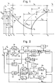
- the device forms an additional device for a control device (not shown) that controls the room temperature, for example as a function of the outside temperature, during an occupancy time T B (FIG. 1) of the building.
- the device takes over control of the building temperature essentially during the occupancy breaks Tp of the building and has control priority over the control commands of the control device, not shown, for the occupancy time T B.
- An A / D converter 1 which essentially converts the outside temperature 9 A and the room temperature 9 R into corresponding electrical signals, is used for the measurement value acquisition.
- the one in claim 1 Computer 2 is used to convert these signals into “building-specific parameters (parameters influenced by the building, including system properties), both for the cooling and for the heating function, the parameters being redetermined for each cycle.
- Part 2a of the further computer 2 serves to determine standardized parameters for the compensation process at the beginning of the occupancy break.
- ⁇ R (tx) means the room temperature at the current time t x and ⁇ A (t0) and ⁇ R (t0) the outside or room temperature at the beginning of the cooling curve 3. Such values result in values for Z (t) between 0 and 1 .
- the computer 2a extrapolates this value from the previous measured values.
- a controller 4 serves to check the suitability of the parameters determined in this way, as will be explained further below. He actuates a release unit 5 which, if the test result is positive, feeds the newly determined parameters to a first memory RAM1.
- a second part 2b of the computer 2 is used to determine parameters of the compensation process with full energy supply, in the example when heating up. There are about 10 values formed for the times 10 to about 300 minutes, as well as a value where this is the difference between the room temperature and the outside temperature at time t u at the beginning of the reheating. Furthermore, the computer 2b determines as a further parameter from a heating curve 6 a time constant caused by the dynamic behavior of the building walls
- ⁇ R ⁇ R (tx) - ⁇ R (tu) ⁇
- ⁇ R ⁇ R (tx) - ⁇ R (tu) ⁇
- ⁇ RN means the value interpolated from the second memory RAM2 described below, to the actual time value t x
- ⁇ is the difference between the filtered value ⁇ N also extracted from the second memory RAM2 and the difference existing at time t u between the room and outside temperature.
- the 12 parameters for the heating process are tested for their suitability and stored in the first memory RAM1 after the heating process has ended.
- a filter F4 is arranged between the first memory RAM1 and the second memory RAM2. It serves as a correlation element for evaluating the new parameters Z t , ⁇ R , ⁇ , a determined after each change of state and stored in the first memory RAM1 with the values stored in the second memory RAM2 from the previous cycle
- the new parameters filtered as described are re-stored in the second memory RAM2 and the old ones are simultaneously deleted.
- the filtered values are subsequently identified by an index N, ie
- a setpoint generator 7 is used to preselect the desired temperature ⁇ s . This directly influences the parameters in the second memory RAM2, but also acts on the controller 4 in the sense that the parameters of this cycle are not evaluated when a setpoint is adjusted within a measurement cycle.
- A is used to pre-calculate the temperature profile of a next temperature drop according to the cooling curve 3 or a reheating according to the heating curve.
- Computer with an associated timer 10 influenced by a programmer 9. This computer periodically calculates taking into account the parameters Z tN or ⁇ RN , ⁇ N , ⁇ N contained in the second memory RAM2 and the current outside and room temperatures ⁇ A or ⁇ R , whether in the event of a change in the energy state of a heating system 11 at the current time t x , that is to say whether by switching off or by fully switching it on again, the required room temperatures ⁇ R (ta) or at predetermined times t a or t e ⁇ R (tc) would be reached.
- the computer 8 depending on the previous state of the system, causes the heating system 11 to be switched off or brought to full power.
- the computer 8a is used for the pre-calculation of the cooling curve 3 (FIG. 1) and the computer 8b is used for the pre-calculation of the heating curve 6.
- the computer 8a begins immediately after the end of each occupancy pause T P , specifically according to the relationship
- the computer 8b starts the pre-calculation of the heating curve 6 immediately after the heating system 11 has been switched off at the time T o, specifically according to the relationship
- the second type of calculation corresponds to the representation in FIG. 2.
- the computer 8a or 8b continuously determines a time period t ra , or t re that is necessary in order to start from the current time t x the desired room temperature ⁇ R (ta ) , or ⁇ R (to) .
- the timing element 10 forms the difference between the time period t xa 'or t xa ' to be expired by the start T A or by the end T E of the occupancy pause Tp and that calculated by the computer 8a or 8b Time period t ra or t re . If a positive time difference value t xa '- t ra or t xo ' - t re disappears , the heating system 11 is switched off at the time T o or the heating system is fully switched on at the time T u .
- the time difference element 10 has three initial states, which are denoted by three rectangles 12, 13, 14 in FIG. 2. These symbolically mean the command status to the energy source, in the example to a heating system 11.
- the device serving as the optimization device is inactive, that is to say the control device takes over the temperature control, usually by actuating an actuator (Curve course 14 of FIG. 1).
- the heating system 11 and the circulation pumps are in operation.
- a limit thermostat 16 which detects the room temperature 0 R and is monitored by the programmer 9 and has a setpoint generator 17 which, if the temperature falls below an adjustable minimum temperature 0 M before the end of the occupancy time T B, prevents a further drop in the room temperature ⁇ R.
- the limit thermostat 16 When activated, the limit thermostat 16, on the one hand, causes a temporary switchover to the control corresponding to the rectangle 13 in FIG. 2, that is, a switchover to the heating program during the occupancy time T B, and on the other hand, it stops the detection of the current one in the release unit 4 Parameter Z t of the cooling cycle started.
- a correction filter F20 also causes, in the case of the response of the limit thermostat 16 via the Korrehtur filter F4 enhanced correction of the contained in the second memory RAM2 parameter Z t is carried out, with a score of about 20%, which means in place of the Correction F4 to 4% limited correction of the new parameter values compared to the old values allows a maximum possible correction of 20%.
- This increased ability to learn is particularly important at the beginning, shortly after the system is started up or after a setpoint change, that is, if the necessary parameters are not yet known and the minimum temperature ⁇ M is therefore below.
- a cooling curve 18 calculated according to incorrect parameters Z t is shown in broken lines, which would cause the heating system 11 to be switched off by the computer 8a at time t x .
- a minimum limiter 21 acting directly on the heating system 11 serves as an anti-freeze thermostat or to prevent condensation by limiting the lowering of the room temperature in the building during the occupancy breaks Tp with large differences between the room temperature and the outside temperature 0 R or 0 A. As soon as its response value is undershot, the minimum limiter 21 switches the heating system 11 on again at most with reduced output and ensures a minimum temperature. The computer 8b then determines the time t e 'for the reheating on the basis of this temperature. The minimum limiter 21 is also operatively connected to the controller 4 connected downstream of the further computer in such a way that when the minimum limiter 21 responds, the evaluation of further cooling parameters Z t is prevented, otherwise incorrect values would result. If necessary, the computer extrapolates the values of the previous curve to form the parameters Z t .
- the device controlling and monitoring the entire process described is advantageously a microcomputer and non-volatile RAM read-only memories are used for the first memory RAM1 and the second memory RAM2, that is to say those which do not lose their memory values in the event of a power failure.
- the device described begins to calculate the necessary heating-up time period t re immediately, i.e. 5 minutes after the end of the occupancy, it is ensured that a heating system 11 which operates at full load even at extremely low outside temperatures and therefore does not have a heating-up reserve maintains the required temperature guaranteed at the end of the occupancy break Tp.
- the theoretical heating-up period t re then becomes approximately the same as the occupancy pause Tp and the heating system continues to operate at full load during the occupancy pause.
- the optimization device described makes the determination of building-specific settings that are difficult to ascertain superfluous.
- the self-learning and self-correcting measurement of the respective building guarantees problem-free use with a wide variety of building dynamic behavior and climatic conditions.
- the previous adjustment difficulties with subsequent service courses for a correction, limited application limits, inaccuracies in different weather or room conditions are avoided.
- control device which controls the room temperature during the occupancy, for example depending on the weather, is largely independent of the optimization device described.
- the latter can work with any control device that may already exist in a system. A mutual agreement that goes beyond the usual setting options of such control units is not necessary.
- the self-learning ability of the device serving as an optimization device makes it possible for the first time Devices can also be used for buildings that are connected to district heating with a constant, sliding supply temperature.
Claims (10)


Applications Claiming Priority (2)
| Application Number | Priority Date | Filing Date | Title |
|---|---|---|---|
| CH13007/78 | 1978-12-21 | ||
| CH1300778A CH638326A5 (de) | 1978-12-21 | 1978-12-21 | Einrichtung zur energiemaessigen optimierung einer temperatur-aenderung in gebaeuden waehrend deren belegungspausen. |
Publications (2)
| Publication Number | Publication Date |
|---|---|
| EP0013287A1 EP0013287A1 (fr) | 1980-07-23 |
| EP0013287B1 true EP0013287B1 (fr) | 1983-10-05 |
Family
ID=4388434
Family Applications (1)
| Application Number | Title | Priority Date | Filing Date |
|---|---|---|---|
| EP79103308A Expired EP0013287B1 (fr) | 1978-12-21 | 1979-09-06 | Dispositif pour l'optimalisation énergétique du changement de température d'un bâtiment à occupation intermittente |
Country Status (3)
| Country | Link |
|---|---|
| EP (1) | EP0013287B1 (fr) |
| CH (1) | CH638326A5 (fr) |
| DE (1) | DE2900946C2 (fr) |
Cited By (2)
| Publication number | Priority date | Publication date | Assignee | Title |
|---|---|---|---|---|
| DE3442441A1 (de) * | 1983-12-24 | 1985-07-04 | Joh. Vaillant Gmbh U. Co, 5630 Remscheid | Verfahren zum ermitteln der fuer eine schnellaufheizung eines raumes benoetigten zeit |
| DE102005057769A1 (de) * | 2005-12-02 | 2007-06-06 | Siemens Ag | Temperatur-Steuervorrichtung und Verfahren zum Betreiben eines Heiz- und/oder Kühlsystems |
Families Citing this family (13)
| Publication number | Priority date | Publication date | Assignee | Title |
|---|---|---|---|---|
| LU82670A1 (fr) * | 1980-07-30 | 1982-02-17 | Leroy Somer Moteurs | Procede pour commander un chauffage d'appoint,regulateur et installation de chauffage s'y rapportant |
| CH667147A5 (de) * | 1985-01-10 | 1988-09-15 | Landis & Gyr Ag | Verfahren und einrichtung zur selbsttaetigen ermittlung der dauer einer schnellaufheizung. |
| DE4009774A1 (de) * | 1990-03-27 | 1991-10-02 | Buderus Heiztechnik Gmbh | Verfahren zur eingabe von programmdaten in einen heizungsregler |
| DE4020093C2 (de) * | 1990-06-23 | 1994-02-24 | Buderus Heiztechnik Gmbh | Verfahren zum Einstellen der Kennlinie einer außentemperaturgeführten Heizungsregelung |
| US5219119A (en) * | 1992-09-21 | 1993-06-15 | Honeywell Inc. | Thermostat-type setback controller having a recovery set point which depends on the time-based value of a sensor signal |
| GB2278207B (en) * | 1993-05-17 | 1996-05-15 | Ea Tech Ltd | Heating control apparatus |
| FR2755262B1 (fr) * | 1996-10-31 | 2002-10-25 | Gaz De France | Procede de programmation du chauffage intermittent d'un batiment et programmateur pour la mise en oeuvre de ce procede |
| KR100550556B1 (ko) * | 2003-11-11 | 2006-02-10 | 엘지전자 주식회사 | 에어컨의 중앙제어 시스템 및 그 동작방법 |
| FR2972578B1 (fr) * | 2011-03-07 | 2017-05-12 | Herve Pouliquen | Dispositif et procede pour l'effacement du chauffage ou de la climatisation |
| GB2508238A (en) * | 2012-11-27 | 2014-05-28 | Aidan Paul Ruff | Apparatus arranged to control a space heating/cooling system |
| FR3039256A1 (fr) * | 2015-07-21 | 2017-01-27 | Ghislain Dubois | Procede et dispositif d'optimisation energetique |
| DE102017218742A1 (de) * | 2017-10-19 | 2019-04-25 | Robert Bosch Gmbh | Verfahren zum Ermitteln einer erwarteten Temperaturkurve sowie Verfahren zum Ermitteln eines Heiz- und/oder Kühlprogramms eines Heiz- und/oder Kühlsystems |
| CN109028483A (zh) * | 2018-05-31 | 2018-12-18 | 佛山市中格威电子有限公司 | 一种用于空调参数修改的无线控制系统 |
Family Cites Families (9)
| Publication number | Priority date | Publication date | Assignee | Title |
|---|---|---|---|---|
| GB1193711A (en) * | 1967-02-24 | 1970-06-03 | Honeywell Ltd Formerly Honeywe | Improvements in or relating to the Control of Thermal Conditioning Systems |
| DE2117374A1 (de) * | 1971-04-08 | 1972-10-19 | Smits M | Verfahren und Vorrichtung zur automatischen Steuerung einer Heizanlage |
| CH567858A5 (fr) * | 1974-01-28 | 1975-10-15 | Grossenbacher Elektronik Ag | |
| GB1463988A (en) * | 1974-02-12 | 1977-02-09 | Satchwell Controls Ltd | Systems for controlling the temperature within an enclosure |
| DK171575A (da) * | 1975-04-21 | 1976-10-22 | J U Christiansen | Kontrolanleg |
| US4024510A (en) * | 1975-08-28 | 1977-05-17 | International Business Machines Corporation | Function multiplexer |
| DE2631476A1 (de) * | 1976-07-13 | 1978-01-19 | Centra Buerkle Gmbh & Co | Verfahren und einrichtung zur beeinflussung der temperatur mindestens eines gebaeuderaumes |
| DE2630920B2 (de) * | 1976-07-09 | 1978-06-08 | Centra-Buerkle Gmbh & Co, 7036 Schoenaich | Anordnung zur Beeinflussung der Temperatur mindestens eines Gebäuderaumes |
| SE408973B (sv) * | 1977-02-16 | 1979-07-16 | Nyberg U L E | Sett och anordning for tidsberoende styrning av ett klimatregleringssystem for en intermittent utnyttjad byggnad |
-
1978
- 1978-12-21 CH CH1300778A patent/CH638326A5/de not_active IP Right Cessation
-
1979
- 1979-01-11 DE DE2900946A patent/DE2900946C2/de not_active Expired
- 1979-09-06 EP EP79103308A patent/EP0013287B1/fr not_active Expired
Cited By (3)
| Publication number | Priority date | Publication date | Assignee | Title |
|---|---|---|---|---|
| DE3442441A1 (de) * | 1983-12-24 | 1985-07-04 | Joh. Vaillant Gmbh U. Co, 5630 Remscheid | Verfahren zum ermitteln der fuer eine schnellaufheizung eines raumes benoetigten zeit |
| DE102005057769A1 (de) * | 2005-12-02 | 2007-06-06 | Siemens Ag | Temperatur-Steuervorrichtung und Verfahren zum Betreiben eines Heiz- und/oder Kühlsystems |
| DE102005057769B4 (de) * | 2005-12-02 | 2010-04-08 | Siemens Ag | Temperatur-Steuervorrichtung und Verfahren zum Betreiben eines Heiz- und/oder Kühlsystems |
Also Published As
| Publication number | Publication date |
|---|---|
| DE2900946A1 (de) | 1980-06-26 |
| DE2900946C2 (de) | 1984-11-08 |
| EP0013287A1 (fr) | 1980-07-23 |
| CH638326A5 (de) | 1983-09-15 |
Similar Documents
| Publication | Publication Date | Title |
|---|---|---|
| EP0013287B1 (fr) | Dispositif pour l'optimalisation énergétique du changement de température d'un bâtiment à occupation intermittente | |
| DE2855227C2 (de) | Verfahren zum Optimieren des Energieverbrauches in Gebäuden sowie Anordnung zur Durchführung des Verfahrens | |
| EP0208256B1 (fr) | Dispositif de régulation de la température d'un local | |
| DE3036082C2 (de) | Steuereinrichtung für eine Wärmepumpe mit geschlossenem Kältemittelkreislauf | |
| EP3589898A1 (fr) | Procédé pour régler une pompe de circulation à vitesse de rotation variable et pompe de circulation | |
| DE2843929B2 (de) | Anordnung zur Steuerung der Raumtemperatur | |
| EP3722680A1 (fr) | Procédé de réalisation d'une comparaison hydraulique d'un système de chauffage pour un bâtiment ainsi que système de chauffage conçu pour celui-ci | |
| DE3300082C2 (fr) | ||
| AT399218B (de) | Verfahren zur steuerung der aufheizung von räumen eines gebäudes | |
| DE3325993C2 (de) | Regeleinrichtung zum Regeln der Temperatur eines zu Heizkörpern vorlaufenden Wärmeträgers | |
| EP3924670A1 (fr) | Procédé pour réguler une pompe de circulation | |
| DE3502873C2 (de) | Verfahren und Einrichtung zur schrittweisen Anpassung einer Heizkennlinie einer Heizeinrichtung | |
| CH667143A5 (de) | Heizkoerperventil mit einer regeleinrichtung zur regelung der raumtemperatur. | |
| DE2809770A1 (de) | Verfahren und anordnung zur beeinflussung der raumtemperatur | |
| DE3538934C2 (fr) | ||
| EP0076398B1 (fr) | Procédé pour régler la température de l'eau de départ respectivement de retour d'une installation de chauffage à eau chaude | |
| DE19952165C2 (de) | Regelverfahren und Regler für elektrisch betriebene Stelleinrichtungen | |
| DE2529858C2 (de) | Verfahren und Vorrichtung zum Regeln einer Wärmeübertragungsanlage | |
| DE102005057769B4 (de) | Temperatur-Steuervorrichtung und Verfahren zum Betreiben eines Heiz- und/oder Kühlsystems | |
| CH678887A5 (fr) | ||
| DE2631476A1 (de) | Verfahren und einrichtung zur beeinflussung der temperatur mindestens eines gebaeuderaumes | |
| EP3431888A1 (fr) | Procédé de mise en uvre d'un équilibre hydraulique d'un système de chauffage et/ou de refroidissement | |
| DE3117789A1 (de) | Verfahren zum regeln bzw. steuern einer heizungsanlage | |
| DE3407795C1 (de) | Heizungsanlage mit Waermepumpe | |
| DE2630920B2 (de) | Anordnung zur Beeinflussung der Temperatur mindestens eines Gebäuderaumes |
Legal Events
| Date | Code | Title | Description |
|---|---|---|---|
| PUAI | Public reference made under article 153(3) epc to a published international application that has entered the european phase |
Free format text: ORIGINAL CODE: 0009012 |
|
| AK | Designated contracting states |
Designated state(s): FR GB IT SE |
|
| 17P | Request for examination filed |
Effective date: 19810116 |
|
| ITF | It: translation for a ep patent filed |
Owner name: STUDIO JAUMANN |
|
| GRAA | (expected) grant |
Free format text: ORIGINAL CODE: 0009210 |
|
| AK | Designated contracting states |
Designated state(s): FR GB IT SE |
|
| ET | Fr: translation filed | ||
| PLBI | Opposition filed |
Free format text: ORIGINAL CODE: 0009260 |
|
| PLBI | Opposition filed |
Free format text: ORIGINAL CODE: 0009260 |
|
| 26 | Opposition filed |
Opponent name: JOH. VAILLANT GMBH U. CO Effective date: 19840530 |
|
| PGFP | Annual fee paid to national office [announced via postgrant information from national office to epo] |
Ref country code: FR Payment date: 19840813 Year of fee payment: 6 |
|
| 26 | Opposition filed |
Opponent name: CENTRA-BUERKLE GMBH Effective date: 19840630 |
|
| PGFP | Annual fee paid to national office [announced via postgrant information from national office to epo] |
Ref country code: SE Payment date: 19840930 Year of fee payment: 6 |
|
| RDAG | Patent revoked |
Free format text: ORIGINAL CODE: 0009271 |
|
| STAA | Information on the status of an ep patent application or granted ep patent |
Free format text: STATUS: PATENT REVOKED |
|
| GBPR | Gb: patent revoked under art. 102 of the ep convention designating the uk as contracting state | ||
| 27W | Patent revoked |
Effective date: 19841218 |
|
| REG | Reference to a national code |
Ref country code: FR Ref legal event code: ST |
|
| EUG | Se: european patent has lapsed |
Ref document number: 79103308.7 Effective date: 19860729 |