EP0011503B2 - Vorrichtung zum Steuern der Geschwindigkeit eines Waschmaschinenmotors - Google Patents
Vorrichtung zum Steuern der Geschwindigkeit eines Waschmaschinenmotors Download PDFInfo
- Publication number
- EP0011503B2 EP0011503B2 EP79302605A EP79302605A EP0011503B2 EP 0011503 B2 EP0011503 B2 EP 0011503B2 EP 79302605 A EP79302605 A EP 79302605A EP 79302605 A EP79302605 A EP 79302605A EP 0011503 B2 EP0011503 B2 EP 0011503B2
- Authority
- EP
- European Patent Office
- Prior art keywords
- speed
- motor
- resistor
- control
- signal
- Prior art date
- Legal status (The legal status is an assumption and is not a legal conclusion. Google has not performed a legal analysis and makes no representation as to the accuracy of the status listed.)
- Expired
Links
- 238000005406 washing Methods 0.000 title claims abstract description 19
- 230000001105 regulatory effect Effects 0.000 claims description 6
- 230000001276 controlling effect Effects 0.000 claims description 5
- 238000009987 spinning Methods 0.000 abstract description 33
- 208000012886 Vertigo Diseases 0.000 description 32
- 239000003990 capacitor Substances 0.000 description 17
- 229920006395 saturated elastomer Polymers 0.000 description 3
- 230000015572 biosynthetic process Effects 0.000 description 2
- 230000000694 effects Effects 0.000 description 2
- 230000001419 dependent effect Effects 0.000 description 1
- 238000010586 diagram Methods 0.000 description 1
- 230000002250 progressing effect Effects 0.000 description 1
- 239000007787 solid Substances 0.000 description 1
- 230000000087 stabilizing effect Effects 0.000 description 1
Images

Classifications
-
- H—ELECTRICITY
- H02—GENERATION; CONVERSION OR DISTRIBUTION OF ELECTRIC POWER
- H02P—CONTROL OR REGULATION OF ELECTRIC MOTORS, ELECTRIC GENERATORS OR DYNAMO-ELECTRIC CONVERTERS; CONTROLLING TRANSFORMERS, REACTORS OR CHOKE COILS
- H02P25/00—Arrangements or methods for the control of AC motors characterised by the kind of AC motor or by structural details
- H02P25/02—Arrangements or methods for the control of AC motors characterised by the kind of AC motor or by structural details characterised by the kind of motor
- H02P25/10—Commutator motors, e.g. repulsion motors
- H02P25/14—Universal motors
- H02P25/145—Universal motors whereby the speed is regulated by measuring the motor speed and comparing it with a given physical value, speed feedback
Definitions
- the present invention relates to a device for controlling the speed of a washing machine motor.
- the motor speed controllers currently being fitted on washing machines are of the solid state type and have a number of advantages over traditional electromechanical designs.
- One of the most outstanding of these advantages is the versatility they afford as regards the functions that can be performed. Thanks to the introduction of solid-state controllers, machines can be made to perform a number of functions which were simply unobtainable at one time.
- One of the many functions a washing machine is called upon to perform is spinning at the end of the washing operation. This spinning operation is performed on known machines in a variety of different ways. Some perform only one type of spinning operation at a single speed regardless of the type of load being washed.
- West German Patent No. 2,715,561 discloses an arrangement in which high and low speeds are controllable separately and independently of each other. However, such an arrangement is relatively complicated for a user to use correctly.
- the aim of the present invention is therefore to enable adjustments to be made to washing machine motor speeds for high and low-speed spinning operations.
- a further aim of the present invention is to enable both speeds to be adjusted simply and cheaply.
- a device for controlling the speed of a washing machine motor during the execution of a single washing programme comprising a regulating element for regulating the speed of the motor in dependence upon a control signal, a circuit for generating the control signal, the latter circuit including a reference signal generating circuit, opertiave to generate a first or second type of signal in order to run the motor at a speed within an acceptable first and second ranges and control means for continuous adjustment of the said first and second type of reference signal so as to provide for continuous control of motor speed within each of the first and second acceptable ranges, characterised in that there is provided a single manually operable means for controlling the said control means to regulate both the first and second speed by means of a single operation in order to obtain a fixed and predetermined ratio between both the first and second speed during the execution of a single washing programme, throughout the range of continuous adjustment of the control means.
- Figure 1 shows the speed controller according to the present invention with reference also to the main parts on the washing machine.
- Terminals 1-1' are supplied with the a.c. mains voltage supplied to motor 2 which controls rotation of the drum on the machine via regulator 3 of the solid-state type using a triac.
- Regulator 3 also receives at its control input 4 a control signal consisting in a suitable trigger current supplied to the triac gate by which it is either disabled or allowed to conduct.
- the frequency of this control signal is higher than that of the a.c. mains voltage so that the control made is commonly referred to as phase angle control.
- the control signal at terminal 4 is generated by a zero cross detecting circuit 5 which receives the a.c. mains voltage at its inputs 6-6' and produces a signal at its output 7 whenever the mains voltage crosses the zero.
- This output 7 signal is supplied to capacitor 8 which also receives a reference signal from output of an amplifier 10.
- the resulting signal at the capacitor terminals is supplied to the input terminal 11 of pulse-forming circuit 12 which generates signal 4 for triggering the triac in regulator 3.
- Input 13 of amplifier 10 receives a signal from an adding circuit 14 which makes an algebraic addition of all incoming signals, on the one hand, from tachometer dynamo 15, connected to motor 2 and, on the other, from reference voltage generator 16.
- Terminal 17 on generator 16 is the terminal which receives the control signal imparted by the user via a single control provided for adjusting motor speed as required during high and low-speed spinning.
- Generator 16 has another three input terminals 18, 19 and 20 connected to three output terminals of a timer 21 via which switch signals are supplied to generator 16 depending on how the machine's washing programme is progressing.
- the motor speed controller When terminals 1-1' are supplied with mains voltage (this occurs during the wash programme when it is necessary to start rotating the drum or start up motor 2), the motor speed controller is enabled to operate.
- the mains voltage at the input of zero cross detecting circuit 5 produces fixed-length pulses at its output 7 which are sent to discharge periodically the capacitor 8 which is constantly charged at the other end by the signal from amplifier 10.
- pulse formation circuit 12 consisting, for example, of a threshold circuit, produces pulses with a variable phase delay as compared with zero crossing. The longer it takes to charge capacitor 8. the longer pulse-formation circuit 12 will take t, produce the trigger signal at its output.
- the triac in regulator 3 will conduct for a greater or lesser period during each half cycle depending on the delay with which it is supplied with trigger pulses from pulse formation circuit 12. Consequently, the longer the triac conducts, the greater the speed of the motor will be.
- the function of the tachometer dynamo associated with adding circuit 14 and reference voltage generator 16 is to create a feedback loop for stabilizing and fixing the speed of the motor according to the reference voltage value. The speed of the motor can therefore be adjusted by regulating the value of the reference voltage.
- the reference voltages at the output of generator 16 can be regulated via timer 21 depending on which stage of the wash programme is being performed by the machine or, for spinning purposes only, by the user for regulating rotation speed according to the type of load being washed.
- Reference voltage generator 16 is designed so that both rotation speeds can be adjusted by means of a single control connected to terminal 17 and depending on whether timer 21 supplies generator 16 with an enabling signal for operating at high or low-speed spinning rates.
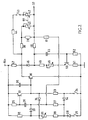
- the direction in which the required adjustment is made for both speeds is the same in both cases; if a speed reduction is needed for slow-spinning operation, the same reduction, must be made to the fast-spinning operation speed. How this twin adjustment can be made using a single control 17 will now be explained with reference to Figure 2 which shows a practical application of reference voltage generator 16 shown in Figure 1.
- -V dc indicates a d.c. current supply terminal.
- the emitter of an NPN transistor 22 which has its collector grounded via a resistor 23 and switch 24 connected in series with one another.
- the base of transistor 22 is connected to terminal -V dc via resistor 25 and to ground via a capacitor 26, resistor 27, diode 28 and switch 29 connected in series with one another.
- Switch 24 is also connected to the anode of diode 54 the cathode of which is connected to the cathode of diode 28.
- the anode of diode 28 is connected to switch 29 while its cathode is also connected to terminal -V dc via resistor 30, variable resistor 31 and resistor 32, connected in series.
- the cathode of diode 33 To the intersection of resistor 32 and resistor 31 is connected the cathode of diode 33 the anode of which is connected to the intersection of condenser 26 and resistor 27.
- the cathode of diode 33 is also connected to the cathode of diode 34 which has its anode connected to the collector of transistor 22.
- the collector of transistor 22 is also connected, at one end. to terminal -V dc , via capacitor 35, and, at the other, to the base of NPN transistor 36.
- the collector of transistor 36 is grounded directly while the emitter is connected to output terminal 37 via two resistors, connected in series, and indicated by numbers 38 and 39.
- a variable resistor 40 is connected parallel to resistor 39.
- Output terminal 37 is also connected at one point to the anode of diode 33 via resistor 41, at another to the emitter of transistor 36 via the series connection of variable resistor 42, switch 43 and resistor 44 and, at another, to the anode of diode 45 via resistor 46.
- Diode 45 has its cathode connected to terminal -V dc via resistor 47 and its anode grounded via the series connection of resistor 48, variable resistor 49, the emitter-collector section of NPN transistor 50 and resistor 51.
- the base of transistor 50 is grounded via resistor 52 and connected to the anode of diode 45 via capacitor 53.
- the slides of variable resistors 40 and 42 are ganged so that the resistance variations of both resistors agree (in this case, in fact, they are the same in that the maximum ratings of both resistors are the same).
- the operation of the device described is as follows:
- the three switches 29, 24 and 43 receive the three control signals 18, 19 and 20 shown in Figure 1 for running the motor at different speeds depending on the washing stage the machine is performing.
- switch 29 When switch 29 is closed, this actuates the so-called “distribution" phase in which the washing is distributed evenly round the edge of the drum by rotating at a speed, for example, of 75 revs/minute.
- Closing of switch 24 actuates the low-speed spinning operation (e.g. 300 revs/ minute). If, in addition to this, switch 43 is also closed, this actuates the high-speed spinning operation (e.g. 600 revs/minute).
- the Figure 2 device generates the different reference voltages required for running the motor at the most suitable speed for the stage in question.
- switch 29 Before switch 29 is closed, the device is already in a position to supply a reference voltage.
- the circuit consisting of transistor 50 and its associated components is supplied and a voltage is available at output terminal 37 mainly dependent on the voltage divider consisting of resistors 47, 48, 49 and 51 and the drop across resistor 46.
- transistor 50 is saturated while all the other active components on the device are disabled.
- the function of capacitor 53 is to hold up supply voltage -V dc so as to enable the motor to reach the required running speed gradually and prevent it from starting up at too high a speed.
- the reference voltage at terminal 37 is such as to run the motor at the "wash" stage speed.
- switch 29 is closed by timer 21 and voltage produced slowly, as a result of the delaying action of capacitor 26, at the anode of diode 33 from which it is supplied to terminal 37 via resistor 41.
- This voltage is added to the existing wash stage voltage so as to produce the voltage increase needed for increasing the speed of the drum and bringing it up gradually (by means of condenser 26) to distribution stage speed.
- transistors 22 and 36 are still disabled owing to diodes 33 and 34 preventing biasing.
- transistors 22 and 36 are also supplied so that the reference voltage is further increased at output terminal 37 via the emitter of transistor 36 and the series connection of resistor 38 and resistor 39 connected parallel to variable resistor 40.
- This further increase in reference voltage brings about the switch to low-speed spinning (maximum speed 400 revs/min).
- speed can be adjusted continuously during this stage between 100 and 400 revs/minute.
- Detailed operation of transistors 22 and 36 and their associated components is as follows: if switch 24 is closed when switch 29 has only been open for a short length of time, capacitor 26 is still charged so that, even if the collector of transistor 22 receives supply voltage, it remains disabled in that, with the capacitor charged, its base receives no biasing current.
- transistor 36 is slowly saturated (owing to the charge of capacitor 35) and the voltage generating at the terminals of the emitter is roughly equal to ground voltage. If switch 24 is closed, however, after capacitor 26 has been discharged (e.g. in the case of a return of mains voltage following a power cut during spinning), when the -V dc voltage returns, transistor 22 is instantly saturated so as to disable transistor 36 and prevent the washing operation from taking up from the spinning stage. With transistor 36 disabled, the device generates a reference voltage corresponding to the distribution stage at output 37. Only when capacitor 26 has been charged and transistor 22 disabled will transistor 36 be able to conduct and supply thie voltage needed for producing the reference voltage at the output for running the motor at low-speed spinning speed.
- resistors 42 and 44 are brought parallel to resistors 38 and 40 so as to reduce the fall in voltage between the emitter of transistor 36 and output terminal 37 and increase the voltage at output terminal 37.
- the output voltage is such that the maximum rotation speed of the drum is 800 revs/minute.
- variable resistors 40 and 42 are ganged and thus adjusted equally by means of a single control, both slow and fast-spinning speeds can be adjusted as required using a single control. Further mention should be made of the importance of certain component functions, in particular variable resistors 40 and 42 and resistors 38, 39 and 44.
- the resistance value chosen for resistor 39 is the one which determines minimum running speed of the motor during slow-spinning operation. In fact, the only effect the adjustment made via resistor 40 has is to reduce the equivalent fall resistance between the emitter of transistor 36 and the output terminal.
- the value chosen for resistor 38 determines the maximum running speed of the motor, again during slow spinning operation.
- resistor 44 determines maximum running speed of the motor during fast-spinning operation while the maximum value of variable resistor 42 must be chosen so that, when it is full on (maximum resistance), its effect is minimum as regards the fall variation caused as compared with slow spinning operation. In this way, the minimum running speed of the motor is practically the same as the minimum slow-spinning speed.
Landscapes
- Engineering & Computer Science (AREA)
- Power Engineering (AREA)
- Control Of Ac Motors In General (AREA)
- Control Of Washing Machine And Dryer (AREA)
Claims (9)
Priority Applications (1)
| Application Number | Priority Date | Filing Date | Title |
|---|---|---|---|
| AT79302605T ATE6395T1 (de) | 1978-11-21 | 1979-11-16 | Vorrichtung zum steuern der geschwindigkeit eines waschmaschinenmotors. |
Applications Claiming Priority (2)
| Application Number | Priority Date | Filing Date | Title |
|---|---|---|---|
| IT6965078 | 1978-11-21 | ||
| IT69650/78A IT1160942B (it) | 1978-11-21 | 1978-11-21 | Dispositivo per regolare la velocita' di rotazione di un motore in una macchina lavabiancheria |
Publications (3)
| Publication Number | Publication Date |
|---|---|
| EP0011503A1 EP0011503A1 (de) | 1980-05-28 |
| EP0011503B1 EP0011503B1 (de) | 1984-02-22 |
| EP0011503B2 true EP0011503B2 (de) | 1988-12-07 |
Family
ID=11312565
Family Applications (1)
| Application Number | Title | Priority Date | Filing Date |
|---|---|---|---|
| EP79302605A Expired EP0011503B2 (de) | 1978-11-21 | 1979-11-16 | Vorrichtung zum Steuern der Geschwindigkeit eines Waschmaschinenmotors |
Country Status (4)
| Country | Link |
|---|---|
| EP (1) | EP0011503B2 (de) |
| AT (1) | ATE6395T1 (de) |
| DE (1) | DE2966712D1 (de) |
| IT (1) | IT1160942B (de) |
Families Citing this family (2)
| Publication number | Priority date | Publication date | Assignee | Title |
|---|---|---|---|---|
| GB2102990A (en) * | 1981-07-31 | 1983-02-09 | Philips Electronic Associated | Drum speed control system for a washing and/or spin drying machine |
| DE3736143A1 (de) * | 1987-10-26 | 1989-05-11 | Telefunken Electronic Gmbh | Schaltung zur einstellung des stromflusswinkels von motoren elektrischer werkzeuge |
Family Cites Families (4)
| Publication number | Priority date | Publication date | Assignee | Title |
|---|---|---|---|---|
| US3511411A (en) * | 1967-12-11 | 1970-05-12 | Ambac Ind | Apparatus for controlling planting and material spraying and spreading device |
| FR2055886A5 (de) * | 1969-08-05 | 1971-05-14 | Tech Trefile Off | |
| CH599382A5 (en) * | 1975-10-24 | 1978-05-31 | Schulthess Ad Maschinenfabrik | Washing or dyeing drum speed regulator |
| DE2715561A1 (de) * | 1977-04-07 | 1978-10-12 | Standard Elektrik Lorenz Ag | Steuerung eines einphasigen asynchronmotors, insbesondere fuer waschmaschinen |
-
1978
- 1978-11-21 IT IT69650/78A patent/IT1160942B/it active
-
1979
- 1979-11-16 EP EP79302605A patent/EP0011503B2/de not_active Expired
- 1979-11-16 AT AT79302605T patent/ATE6395T1/de not_active IP Right Cessation
- 1979-11-16 DE DE7979302605T patent/DE2966712D1/de not_active Expired
Also Published As
| Publication number | Publication date |
|---|---|
| IT1160942B (it) | 1987-03-11 |
| IT7869650A0 (it) | 1978-11-21 |
| EP0011503A1 (de) | 1980-05-28 |
| ATE6395T1 (de) | 1984-03-15 |
| DE2966712D1 (en) | 1984-03-29 |
| EP0011503B1 (de) | 1984-02-22 |
Similar Documents
| Publication | Publication Date | Title |
|---|---|---|
| US4574226A (en) | Method and apparatus for controlling an electric motor the rotational speed of which is automatically reduced in no-load idling operation | |
| US4259845A (en) | Logic control system for inverter-driven motor | |
| US3443188A (en) | Switching circuits | |
| US3935522A (en) | Control device for the electric fan | |
| JPH0632600B2 (ja) | 発電機の電圧調整回路 | |
| CA1217260A (en) | Airflow control system | |
| US4326153A (en) | Feedback motor control circuit | |
| US4150303A (en) | Motor speed control circuits | |
| EP0011503B2 (de) | Vorrichtung zum Steuern der Geschwindigkeit eines Waschmaschinenmotors | |
| GB1266691A (de) | ||
| US3967179A (en) | Power supply for a stepping motor | |
| US3441825A (en) | Selected gain control system | |
| US4332208A (en) | Sewing machine speed control circuit | |
| US4236390A (en) | Knitting machine | |
| US3358206A (en) | Pulse width modulation control systems for controlling direct current motors | |
| US3233163A (en) | Plural speed tachometer-generator speed control system | |
| DE69210891T2 (de) | Elektronischer Ein- und Ausblendeschalter | |
| KR100226717B1 (ko) | 스테핑 모터의 구동 회로 | |
| EP0331251A2 (de) | Überspannungsschutzanordnung für Steuerschaltungen mit Lasttransistoren | |
| US3622853A (en) | Control circuits for clothes washing and spin-drying machines | |
| RU1794009C (ru) | Способ регулировани скорости надвигани пилы при распиловке лесоматериалов и устройство дл его осуществлени | |
| SU1440989A1 (ru) | Устройство дл управлени швейной машиной | |
| JPS55150793A (en) | Speed-control device for sewing machine | |
| US2458131A (en) | Control of energy supplied to translating devices | |
| SU883547A1 (ru) | Электрогидравлический регул тор скорости гидротурбины |
Legal Events
| Date | Code | Title | Description |
|---|---|---|---|
| PUAI | Public reference made under article 153(3) epc to a published international application that has entered the european phase |
Free format text: ORIGINAL CODE: 0009012 |
|
| AK | Designated contracting states |
Designated state(s): AT BE DE FR GB NL |
|
| 17P | Request for examination filed | ||
| GRAA | (expected) grant |
Free format text: ORIGINAL CODE: 0009210 |
|
| AK | Designated contracting states |
Designated state(s): AT BE DE FR GB NL |
|
| PG25 | Lapsed in a contracting state [announced via postgrant information from national office to epo] |
Ref country code: NL Effective date: 19840222 Ref country code: FR Free format text: THE PATENT HAS BEEN ANNULLED BY A DECISION OF A NATIONAL AUTHORITY Effective date: 19840222 Ref country code: BE Effective date: 19840222 Ref country code: AT Effective date: 19840222 |
|
| REF | Corresponds to: |
Ref document number: 6395 Country of ref document: AT Date of ref document: 19840315 Kind code of ref document: T |
|
| REF | Corresponds to: |
Ref document number: 2966712 Country of ref document: DE Date of ref document: 19840329 |
|
| NLV1 | Nl: lapsed or annulled due to failure to fulfill the requirements of art. 29p and 29m of the patents act | ||
| EN | Fr: translation not filed | ||
| PLBI | Opposition filed |
Free format text: ORIGINAL CODE: 0009260 |
|
| 26 | Opposition filed |
Opponent name: BOSCH-SIEMENS HAUSGERAETE GMBH, STUTTGART Effective date: 19841116 |
|
| PUAH | Patent maintained in amended form |
Free format text: ORIGINAL CODE: 0009272 |
|
| STAA | Information on the status of an ep patent application or granted ep patent |
Free format text: STATUS: PATENT MAINTAINED AS AMENDED |
|
| 27A | Patent maintained in amended form |
Effective date: 19881207 |
|
| AK | Designated contracting states |
Kind code of ref document: B2 Designated state(s): AT BE DE FR GB NL |
|
| EN3 | Fr: translation not filed ** decision concerning opposition | ||
| PGFP | Annual fee paid to national office [announced via postgrant information from national office to epo] |
Ref country code: GB Payment date: 19961107 Year of fee payment: 18 |
|
| PGFP | Annual fee paid to national office [announced via postgrant information from national office to epo] |
Ref country code: DE Payment date: 19961122 Year of fee payment: 18 |
|
| PG25 | Lapsed in a contracting state [announced via postgrant information from national office to epo] |
Ref country code: GB Free format text: LAPSE BECAUSE OF NON-PAYMENT OF DUE FEES Effective date: 19971116 |
|
| GBPC | Gb: european patent ceased through non-payment of renewal fee |
Effective date: 19971116 |
|
| PG25 | Lapsed in a contracting state [announced via postgrant information from national office to epo] |
Ref country code: DE Free format text: LAPSE BECAUSE OF NON-PAYMENT OF DUE FEES Effective date: 19980801 |