EP0010924A1 - Drainage device for papermaking and other similar machines, and method of making the device - Google Patents
Drainage device for papermaking and other similar machines, and method of making the device Download PDFInfo
- Publication number
- EP0010924A1 EP0010924A1 EP79302323A EP79302323A EP0010924A1 EP 0010924 A1 EP0010924 A1 EP 0010924A1 EP 79302323 A EP79302323 A EP 79302323A EP 79302323 A EP79302323 A EP 79302323A EP 0010924 A1 EP0010924 A1 EP 0010924A1
- Authority
- EP
- European Patent Office
- Prior art keywords
- wafers
- body portion
- accordance
- main body
- base plate
- Prior art date
- Legal status (The legal status is an assumption and is not a legal conclusion. Google has not performed a legal analysis and makes no representation as to the accuracy of the status listed.)
- Withdrawn
Links
- 238000004519 manufacturing process Methods 0.000 title claims abstract description 18
- 235000012431 wafers Nutrition 0.000 claims abstract description 101
- 239000000463 material Substances 0.000 claims abstract description 41
- 239000000919 ceramic Substances 0.000 claims abstract description 14
- 239000007788 liquid Substances 0.000 claims abstract description 8
- 238000000034 method Methods 0.000 claims description 15
- 239000000853 adhesive Substances 0.000 claims description 14
- 230000001070 adhesive effect Effects 0.000 claims description 14
- 239000000758 substrate Substances 0.000 claims description 8
- 239000004593 Epoxy Substances 0.000 claims description 7
- 229920005989 resin Polymers 0.000 claims description 6
- 239000011347 resin Substances 0.000 claims description 6
- 229910010293 ceramic material Inorganic materials 0.000 claims description 2
- 238000000605 extraction Methods 0.000 claims description 2
- 239000003365 glass fiber Substances 0.000 claims description 2
- 230000014759 maintenance of location Effects 0.000 claims 1
- 229920006395 saturated elastomer Polymers 0.000 claims 1
- 239000011888 foil Substances 0.000 description 37
- XLYOFNOQVPJJNP-UHFFFAOYSA-N water Substances O XLYOFNOQVPJJNP-UHFFFAOYSA-N 0.000 description 11
- PNEYBMLMFCGWSK-UHFFFAOYSA-N Alumina Chemical compound [O-2].[O-2].[O-2].[Al+3].[Al+3] PNEYBMLMFCGWSK-UHFFFAOYSA-N 0.000 description 4
- 238000011161 development Methods 0.000 description 4
- 230000018109 developmental process Effects 0.000 description 4
- 239000011152 fibreglass Substances 0.000 description 4
- 239000012530 fluid Substances 0.000 description 4
- 239000010410 layer Substances 0.000 description 4
- 230000015572 biosynthetic process Effects 0.000 description 3
- 238000000926 separation method Methods 0.000 description 3
- 229920003332 Epotuf® Polymers 0.000 description 2
- 239000012790 adhesive layer Substances 0.000 description 2
- 230000008901 benefit Effects 0.000 description 2
- 210000000481 breast Anatomy 0.000 description 2
- 230000003750 conditioning effect Effects 0.000 description 2
- 238000010276 construction Methods 0.000 description 2
- 230000008602 contraction Effects 0.000 description 2
- 238000009434 installation Methods 0.000 description 2
- 238000004026 adhesive bonding Methods 0.000 description 1
- 239000007767 bonding agent Substances 0.000 description 1
- 238000011109 contamination Methods 0.000 description 1
- 229920006332 epoxy adhesive Polymers 0.000 description 1
- 238000003475 lamination Methods 0.000 description 1
- 239000004848 polyfunctional curative Substances 0.000 description 1
- 230000000717 retained effect Effects 0.000 description 1
- 238000010008 shearing Methods 0.000 description 1
- 239000000126 substance Substances 0.000 description 1
- 238000003466 welding Methods 0.000 description 1
Images

Classifications
-
- D—TEXTILES; PAPER
- D21—PAPER-MAKING; PRODUCTION OF CELLULOSE
- D21F—PAPER-MAKING MACHINES; METHODS OF PRODUCING PAPER THEREON
- D21F1/00—Wet end of machines for making continuous webs of paper
- D21F1/48—Suction apparatus
- D21F1/483—Drainage foils and bars
Definitions
- a moving endless wire screen carrying paper stock is passed over a series of conditioning stations, and over the years these have been the subject of a variety of improvements to make the papermaking process more efficient, inexpensive, and generally better.
- the moving wire screen encounters two major stations for conditioning the wet material carried by it. At the first, the wire screen passes over a series of rollers, stationary foils, or doctor blades, and at the second it passes over a series of suction boxes. At both stations, the general objective is to remove water or other liquid from the paper stock, in other words to drain water therefrom. Suction can also be applied at the first station as well as at the suction box station.
- a serious difficulty that arises when dealing with ceramics is that manufacture of ceramics in large sections creates cost problems in respect to both manufacture and installation. Furthermore, in the past, attempts at developing ceramic wear surfaces from smaller component parts or smaller ceramic pieces mounted together with other structures have resulted in increased manufacturing and installation costs as well as difficulties in operation. This is particularly true in respect of the tendency for one or more of the smaller ceramic components to become displaced or disoriented with respect to the others during fabrication or use of the drainage device, i.e. the drainage foil or suction box cover. This is a particular problem where the screen is heavy and is continuously passed at high speed over the surface, such as in the common type of Fourdrinier papermaking machine.
- a drainage device for papermaking machines and other similar machines in which drainage devices are mounted beneath a moving screen so as to support the screen and engage its undersurface to promote the extraction of liquid downwardly through the screen from material carried by the screen, the drainage device comprising a main body portion and a wear resistant portion providing a wear surface for engaging the undersurface of the screen and doctoring liquid therefrom as the screen moves over the device, is characterised in that the wear resistant portion is formed by a multiplicity of wear resistant wafers which are fixed on the main body portion by a bonding material so that the upper surfaces of the wafers form the wear surface, and that the main body portion and the wear resistant wafers have substantially the same coefficient of thermal expansion.
- the method of making the drainage device comprises aligning the multiplicity of wear resistant wafers on a base plate and holding the aligned wafers in their set position on the base plate, applying a predetermined amount of the bonding material to the exposed surface of the wafers remote from the base plate to form a layer of the bonding material on the wafers, supporting the main body portion in engagement with the layer of bonding material while the bonding material sets to bond the wafers to the body portion, and releasing the wafers from the base plate so that the drainage device formed by the main body portion and the wafers bonded thereto can be removed from the base plate, the faces of the wafers in contact with the base plate forming the wear surface of the device.
- the drainage device may be formed of a minimum number of components which are of inexpensive material and, as mentioned above, are inexpensively and easily assembled to produce an ultimate component that can be easily and quickly installed and replaced.
- the wear resistant wafers are made of a ceramic material and are relatively small and thin, and are rectangular in shape.
- the main body portion may be made of resin impregnated glass fibres, and the bonding material may be an epoxy based adhesive. The resulting device is highly wear resistant while being subjected to normal wear conditions.
- the suction boxes 26 have suction box covers which act as supports for the wire screen and contain apertures for suction to draw additional moisture from the stock contained on the wire screen 23.
- the screen carrying drained stock passes around a couch roll 28, and the stock is removed from the screen as the direction of the screen is changed downwards until it engages and passes around a forward driving roll 30 which is attached to an appropriate drive source (not shown) to advance the endless wire screen 23.
- the direction is thus changed so that the screen then passes over an arrangement of return rolls 32 until it again comes into contact with the breast roll 24 and is returned to the upper working surface of the Fourdrinier papermaking machine for the deposit of a new supply of substrate.
- a multiplicity of wafers 40 of a wear resistant material, such as ceramic, are placed in rows in side by side relationship on the upper surface 38 of the base plate 34.
- the suction applied through the openings 36 holds the wafers 40 in the pattern in which they are arranged.
- the wafers 40 are rectangular and are arranged side by side in rows so that the join lines 42 between the wafers in each row are offset with respect to the join lines between the wafers of the adjacent row or rows.
- this offset arrangement may not be used in all constructions.
- the rows are arranged parallel so that the adjoining longitudinal edges 44 of the rows are parallel to one another as depicted in Figure 5.
- a single row of wafers 40 may be provided instead of an arrangement of two or more parallel rows.
- the number of rows of wafers is a matter of choice depending on the dimensions of wafer used, desired dimensions for the wear surface and other specific design considerations.
- the base plate 34 is provided with an abutment providing a reference or straight edge 46 extending upwards from the upper surface 38 to form an alignment surface for the multiplicity of wafers 40 as they are placed in position.
- the wafers may have a variety of configurations, and as shown they are small and thin in structure. Thus they can be inexpensively manufactured, and quickly and efficiently assembled to form the wear surface for the foil 20. It has been found that wafers which are about 50.8 mms long, about 15.9 mms wide, and about 3.2:'mms thick, work effectively for this purpose.
- the vacuum applied through openings 36 and chamber 37 assists in retaining this desired multiplicity arrangement.
- the leading edge 49 of the wafers 40 adjacent the reference 46 is bevelled to form an edge for the ultimate foil to use in doctoring fluid from a moving screen.
- the next step is to apply a predetermined amount of bonding material 47, such as a conventional epoxy based adhesive, on the upper surface 48 of the wafers 40 to form a layer.
- a predetermined amount of bonding material 47 such as a conventional epoxy based adhesive
- the adhesive is carefully metered out in a relatively precise amount so that there is not an excess of adhesive present.
- the main body portion 50 of the drainage device 20 is positioned on the adhesive layer and retained thereon until it is bonded, by means of the adhesive, to the multiplicity of wafers 40 to complete the drainage foil 20.
- the vacuum is continually applied to assist in holding the wafers 40 in the desired position and pattern.
- the main body portion 50 has a recess 52 formed at one edge and terminating in a shoulder 54 inwardly positioned from the edge.
- the recess 52 forms a reception area for the multiplicity of wafers 40, and the shoulder 54 cooperates with the straight edge 46 in retaining them in aligned and closely adjacent position.
- the recess 52 captures the adhesive on the surface 48 and assists in preventing adhesive from being forced outwards and away from the wafers when the main body portion 50 is applied thereon. This helps to prevent the undesirable manufacturing result of adhesive being exposed for contamination of the surrounding area.
- a shim 45 is provided between the main body portion 50 and the upper surface 38 of the base plate 34 in a location displaced from the wafers 40 to support the body portion 50 on the plate 34 and to help maintain the bond gap between the body portion and the wafers equal to or a slightly less than the thickness of the adhesive layer 47 until the bonding is complete.
- An effective material for the main body portion 50 has been found to be a substrate of fibre glass reinforced resin, referred to as resin bonded fibre glass, or similar conventional well known substitutes therefor. After the main body portion 50 has been engaged with the adhesive 47 on the surface 48 of the multiplicity of wafers 40, the combination is allowed to stand and cure in accordance with conventional manufacturing procedures.
- the coefficients of linear thermal expansion per degree Fahrenheit for the wafers and the main body portion are 6.8 x 10" and 5.2 x 10- 6 respectively. Each of these coefficients is within 15% of the mean coefficient of the two.
- the coefficient of thermal expansion of the main body portion is substantially greater than that of the wear resistant wafers, gaps can occur in the wear surface of the foil due to separation of the wafers upon temperature rise. Certain amounts of gap separation are acceptable, however, depending upon web characteristics. Likewise, upon a decrease of temperature, the wafers can be compacted by the contraction of the main body portion, which can create undesirable shearing forces in the bond material. The bond shear strength should be equal to or greater than the shear forces resulting from expansion or contraction.
- an irregularly shaped tongue 51 extends from the side of the main body portion 50 opposite to the side containing the wear surface formed by the multiplicity of wafers 40.
- the tongue 51 facilitates mounting of the foil 20 in a papermaking machine in a conventional manner.
- apertures can be provided in a conventional manner so that when the suction box 26 is mounted in a papermaking machine in the position as shown in Figure 1, the use of suction can be taken advantage of in working with the box 26 in removing or doctoring water from the material on the wire screen or web 23.
- the drainage foil 20 is inverted from the position in which it is manufactured, as shown in Figure 6.
- the multiplicity of wafers 40 form the wear surface as the foil 20 is removed from the upper surface 38 of the base plate 34.
- the foil is then mounted in a conventional manner on the Fourdrinier machine.
- the multiplicity of wafers formed in the manner described above are thus interconnected in a tight strongly knit fashion so that they cannot be easily displaced during operation of the papermaking machine and when subjected to wear in doctoring fluid and supporting the moving wire screen.
- This method can be used in all applications of drainage devices including foils or suction boxes.
- Other similar types of wear surfaces which are used in similar environments can also be manufactured in the same manner with the same effective ultimate results.
Landscapes
- Paper (AREA)
- Pharmaceuticals Containing Other Organic And Inorganic Compounds (AREA)
Abstract
A drainage device 20, which is arranged to be mounted in a papermaking machine beneath a moving screen of the machine so as to support the screen and to engage its undersurface as it passes thereover to extract liquid downwardly through the screen from the material carried by the screen, comprises a main body portion 50 and a multiplicity of wear resistant ceramic wafers 40 bonded thereto with the upper surface of the wafers 40 providing the device with a wear surface for engaging the undersurface of the screen as it passes over the device. The method of fabricating the drainage device 20 includes the steps of positioning and holding the multiplicity of ceramic wafers 40, wear surface downwards, on a base plate 34, metering a predetermined amount of the bonding material 47 onto the exposed surfaces of the wafers 40, and positioning the main body portion 50 over the wafers 40 in engagement with the bonding material 47.
Description
- In the traditional type of papermaking machine, known as a Fourdrinier machine, a moving endless wire screen carrying paper stock is passed over a series of conditioning stations, and over the years these have been the subject of a variety of improvements to make the papermaking process more efficient, inexpensive, and generally better. The moving wire screen encounters two major stations for conditioning the wet material carried by it. At the first, the wire screen passes over a series of rollers, stationary foils, or doctor blades, and at the second it passes over a series of suction boxes. At both stations, the general objective is to remove water or other liquid from the paper stock, in other words to drain water therefrom. Suction can also be applied at the first station as well as at the suction box station.
- The general trend has been towards the use of a stationary doctor blade or drainage foil rather than rollers at the first station, and various improvements in this type of structure have appeared through the years. The improvements have been primarily in changes in configuration for the foil, replacement portions for the foil, and means for mounting and replacing the foil, as well as the provision of improved wear surfaces for engagement with the moving screen of the papermaking machine. These criteria have been found to be of great importance in this type of structure since the wire screen moves at a very high speed. Also, this screen with the wet sheet of stock material is quite heavy, and the stationary foil must support this weighted moving wire screen as water is doctored or drained from the screen. The surface of the foil in engagement with the moving wire screen is therefore subjected to high wear conditions and must be replaced frequently. Thus, ease of replacement is important and improvements in this area have been made so that the machine will be out of operation forthe minimum possible time while foils are being replaced. Additionally, different types of wear surfaces which are harder and subject to less deteriation due to wear over longer periods of time have been developed. Due to economic considerations and replacement considerations, these harder wear surfaces are often formed as part of the foil.
- After the moving wire screen and transported paper stock material passes the first station, it comes into contact with a series of suction boxes which further draw water from the paper stock or material on the moving screen. The suction boxes are arranged so that their covers provide an upper wear surface and have apertures therein. The wire screen passes over, and is supported by, the upper wear surfaces of the suction boxes while vacuum draws water through the apertures. Thus, in general, the wear criteria dealing with the nature of the surface of the stationary foil which is in contact with the moving wire screen at the first station is also applicable to the surface of the suction box cover which is in similar direct engagement with the moving wire screen at the second station. Similar developments in attempting to improve the wear surface have occured in regard to suction box covers and so called forming surfaces as shown in British Patent Specification No. 1,403,158.
- One area of development in regard to improving the wear surfaces of stationary drainage foils and suction box covers deals with the use of a ceramic wear surface which has a number of the desired characteristics for the surface as discussed above. Three developments relating to suction box covers which specifically discuss the use of ceramics are described in United States Patent Specifications Nos. 3,067,816; 3,250,671; and 3,351,524.
- A serious difficulty that arises when dealing with ceramics is that manufacture of ceramics in large sections creates cost problems in respect to both manufacture and installation. Furthermore, in the past, attempts at developing ceramic wear surfaces from smaller component parts or smaller ceramic pieces mounted together with other structures have resulted in increased manufacturing and installation costs as well as difficulties in operation. This is particularly true in respect of the tendency for one or more of the smaller ceramic components to become displaced or disoriented with respect to the others during fabrication or use of the drainage device, i.e. the drainage foil or suction box cover. This is a particular problem where the screen is heavy and is continuously passed at high speed over the surface, such as in the common type of Fourdrinier papermaking machine.
- Accordingly, there is still room for improvement in the development of drainage devices such as foils and suction box covers in order to satisfy all of the desired criteria for this type of structure for use in papermaking machinery and other similar types of machine, and it is to such drainage devices and their method of manufacture that the present invention relates.
- According to one aspect of the invention, a drainage device for papermaking machines and other similar machines in which drainage devices are mounted beneath a moving screen so as to support the screen and engage its undersurface to promote the extraction of liquid downwardly through the screen from material carried by the screen, the drainage device comprising a main body portion and a wear resistant portion providing a wear surface for engaging the undersurface of the screen and doctoring liquid therefrom as the screen moves over the device,is characterised in that the wear resistant portion is formed by a multiplicity of wear resistant wafers which are fixed on the main body portion by a bonding material so that the upper surfaces of the wafers form the wear surface, and that the main body portion and the wear resistant wafers have substantially the same coefficient of thermal expansion.
- According to the second aspect of the invention the method of making the drainage device comprises aligning the multiplicity of wear resistant wafers on a base plate and holding the aligned wafers in their set position on the base plate, applying a predetermined amount of the bonding material to the exposed surface of the wafers remote from the base plate to form a layer of the bonding material on the wafers, supporting the main body portion in engagement with the layer of bonding material while the bonding material sets to bond the wafers to the body portion, and releasing the wafers from the base plate so that the drainage device formed by the main body portion and the wafers bonded thereto can be removed from the base plate, the faces of the wafers in contact with the base plate forming the wear surface of the device.
- The drainage device can be manufactured at a minimum cost and readily and efficiently installed and replaced at low cost while retaining the benefits of a high quality hard ceramic wear surface for engagement with the moving screen. The drainage device is both rigid and strong, and is designed so that it provides an efficient wear surface which is adapted for maximum wear resistance without detracting from the speed and effective movement of the moving wire screen while supporting the screen and subjecting it to doctoring or drainage of water or other fluid therefrom. Additionally, the design lends itself to application of suction to cooperate with the doctoring action of the wear surface in assisting in removing water or other fluid from the substrate on the moving endless screen.
- The drainage device may be formed of a minimum number of components which are of inexpensive material and, as mentioned above, are inexpensively and easily assembled to produce an ultimate component that can be easily and quickly installed and replaced. Preferably the wear resistant wafers are made of a ceramic material and are relatively small and thin, and are rectangular in shape. The main body portion may be made of resin impregnated glass fibres, and the bonding material may be an epoxy based adhesive. The resulting device is highly wear resistant while being subjected to normal wear conditions.
- In accordance with the invention the main body portion and the wear resistant wafers should have substantially the'same coefficient of thermal expansion as eachother. In other words, the coefficients of thermal expansion of the wafers and the main body portion should not be greatly different, and preferably the coefficients should be within 15% of the mean.
- Although the wear surface structure and its method of formation are discussed herein in terms primarily of a drainage foil, it is equally applicable in the formation of other types of similar drainage devices, such as suction box covers, which serve to drain wires in the Fourdrinier section or felts in the press section of a papermaking machine. Examples of the drainage device in accordance with the invention, and the method of manufacture will now be described with reference to the accompanying drawings, in which:-
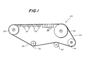
- Figure 1 is a schematic view of the arrangement of the endless wire screen of a Fourdrinier type papermaking machine provided with a group of drainage foils constructed in accordance with the present invention;
- Figures 2 to 4 are a sequence of sectional views showing different steps in the manfucture of a drainage foil in accordance with the invention;
- Figure 5 is a fragmentary top plan view of the wear surface of a drainage foil in accordance with the invention;
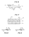
- Figure 6 is a sectional view of a drainage foil formed by the method illustrated in Figures 2 to 4;
- Figure 7 is a fragmentary sectional view illustrating an alternative form of construction for the drainage foil in accordance with the invention; and,
- Figures 8 and 9 are views similar to Figure 2, but illustrating alternative ways of carrying out the manufacturing step of Figure 2.
-
Drainage foils 20 are shown in Figure 1 as part of a typical Fourdrinier papermaking machine system. The portion of the papermaking machine which is depicted includes a Fourdrinierwire screen 23 in the form of an endless belt. Thewire screen 23 passes around abreast roll 24, and thereafter a substrate of wet stock paper material (not shown) is positioned on the porous wire screen. Thescreen 23 then passes into engagement with the supporting surface ofdrainage foils 20 which doctor or draw water from the screen.Suction boxes 26, downstream fromthelfoils 20 also assist in drawing water from the screen. - The
suction boxes 26 have suction box covers which act as supports for the wire screen and contain apertures for suction to draw additional moisture from the stock contained on thewire screen 23. The screen carrying drained stock passes around acouch roll 28, and the stock is removed from the screen as the direction of the screen is changed downwards until it engages and passes around aforward driving roll 30 which is attached to an appropriate drive source (not shown) to advance theendless wire screen 23. The direction is thus changed so that the screen then passes over an arrangement ofreturn rolls 32 until it again comes into contact with thebreast roll 24 and is returned to the upper working surface of the Fourdrinier papermaking machine for the deposit of a new supply of substrate. - Referring now to Figures 2 to 4 in which the manufacture of the
drainage foils 20 is illustrated, a level orhorizontal base plate 34 forms a working surface for the formation of the foil. Thebase plate 34 has a pluarlity of spacedholes 36 therethrough leading into achamber 37 so that when thechamber 37 is attached to a source of suction (not shown) the suction applied through thevacuum chamber 37 and communicatingapertures 36, as indicated by the arrow in Figure 2, will tend to hold items placed on theupper surface 38 of the plate. Other means for holding items in position on thesurface 38 may be employed, and two specific alternative forms are described below with reference to Figures 8 and 9. Thevacuum chamber 37 is provided by a flanged channel mounted on the underside of thebase plate 34 in a conventional fashion, such as by welding. - With the suction connected to the
vacuum chamber 37, a multiplicity ofwafers 40 of a wear resistant material, such as ceramic, are placed in rows in side by side relationship on theupper surface 38 of thebase plate 34. The suction applied through theopenings 36 holds thewafers 40 in the pattern in which they are arranged. In the particular example illustrated in Figure 5, thewafers 40 are rectangular and are arranged side by side in rows so that thejoin lines 42 between the wafers in each row are offset with respect to the join lines between the wafers of the adjacent row or rows. However, this offset arrangement may not be used in all constructions. The rows are arranged parallel so that the adjoininglongitudinal edges 44 of the rows are parallel to one another as depicted in Figure 5. Alternatively, a single row ofwafers 40 may be provided instead of an arrangement of two or more parallel rows. - The number of rows of wafers is a matter of choice depending on the dimensions of wafer used, desired dimensions for the wear surface and other specific design considerations. The
base plate 34 is provided with an abutment providing a reference orstraight edge 46 extending upwards from theupper surface 38 to form an alignment surface for the multiplicity ofwafers 40 as they are placed in position. The wafers may have a variety of configurations, and as shown they are small and thin in structure. Thus they can be inexpensively manufactured, and quickly and efficiently assembled to form the wear surface for thefoil 20. It has been found that wafers which are about 50.8 mms long, about 15.9 mms wide, and about 3.2:'mms thick, work effectively for this purpose. As the wafers are placed in position, they are pushed against previously placed wafers and, accordingly, are urged against thestraight edge 46, and thus are maintained in tight aligned interengagement. The vacuum applied throughopenings 36 andchamber 37 assists in retaining this desired multiplicity arrangement. The leadingedge 49 of thewafers 40 adjacent thereference 46 is bevelled to form an edge for the ultimate foil to use in doctoring fluid from a moving screen. - The next step, as shown in Figure 3, is to apply a predetermined amount of bonding material 47, such as a conventional epoxy based adhesive, on the
upper surface 48 of thewafers 40 to form a layer. The adhesive is carefully metered out in a relatively precise amount so that there is not an excess of adhesive present. - Thereafter, as shown in Figure 4, the
main body portion 50 of thedrainage device 20 is positioned on the adhesive layer and retained thereon until it is bonded, by means of the adhesive, to the multiplicity ofwafers 40 to complete thedrainage foil 20. During the steps of Figures 3 and 4, the vacuum is continually applied to assist in holding thewafers 40 in the desired position and pattern. Themain body portion 50 has arecess 52 formed at one edge and terminating in ashoulder 54 inwardly positioned from the edge. Therecess 52 forms a reception area for the multiplicity ofwafers 40, and theshoulder 54 cooperates with thestraight edge 46 in retaining them in aligned and closely adjacent position. Additionally, therecess 52 captures the adhesive on thesurface 48 and assists in preventing adhesive from being forced outwards and away from the wafers when themain body portion 50 is applied thereon. This helps to prevent the undesirable manufacturing result of adhesive being exposed for contamination of the surrounding area. Ashim 45 is provided between themain body portion 50 and theupper surface 38 of thebase plate 34 in a location displaced from thewafers 40 to support thebody portion 50 on theplate 34 and to help maintain the bond gap between the body portion and the wafers equal to or a slightly less than the thickness of the adhesive layer 47 until the bonding is complete. - An effective material for the
main body portion 50 has been found to be a substrate of fibre glass reinforced resin, referred to as resin bonded fibre glass, or similar conventional well known substitutes therefor. After themain body portion 50 has been engaged with the adhesive 47 on thesurface 48 of the multiplicity ofwafers 40, the combination is allowed to stand and cure in accordance with conventional manufacturing procedures. - The danger of pressure forcing epoxy bonding material from between the undersurface of the
main body portion 50 and the upper surface of the wafers during fabrication is largely avoided since the separation of these members is held constant by theshim 45, and the epoxy is located in therecess 52. - It has been found to be effective to make the wafers of ceramic or aluminium oxide, and to make the wafers and the main body portion with similar coefficients of thermal expansion. For example, in one case the coefficients of linear thermal expansion per degree Fahrenheit for the wafers and the main body portion are 6.8 x 10" and 5.2 x 10⁻⁶ respectively. Each of these coefficients is within 15% of the mean coefficient of the two.
- If the coefficient of thermal expansion of the main body portion is substantially greater than that of the wear resistant wafers, gaps can occur in the wear surface of the foil due to separation of the wafers upon temperature rise. Certain amounts of gap separation are acceptable, however, depending upon web characteristics. Likewise, upon a decrease of temperature, the wafers can be compacted by the contraction of the main body portion, which can create undesirable shearing forces in the bond material. The bond shear strength should be equal to or greater than the shear forces resulting from expansion or contraction.
- A three part laminate of the wafers, an epoxy bonding agent, and a resin bonded fibre glass body portion provides an effective wear surface for use in papermaking machinery. In this manner, a means is provided for bonding ceramic to a support substrate for economical use as a long time wear surface. One successful lamination includes an all Alumina ceramic arrangement of wafers, a two part epoxy adhesive with the commonly known hardener Epotuf, and a resin impregnated fibre glass body portion. Epotuf is a registered trademark of Reichold Chemicals Inc.
- Figures 8 and 9 illustrate alternative ways of holding the wafers in alignment during fabrication of the drainage device. In both Figures the horizontal base plate is designated by the numeral 34a and is similar to the
base plate 34 described above except that theholes 36 andvacuum chamber 37 are omitted. Instead, in the arrangement of Figure 8 anadhesive member 36a is used to hold thewafers 40a in position, and in the arrangement of Figure 9 a magnetic member 36b is used to hold the wafers 40b in position. Otherwise the method of making the foils is the same as described above. - As shown in Figure 6 an irregularly shaped
tongue 51 extends from the side of themain body portion 50 opposite to the side containing the wear surface formed by the multiplicity ofwafers 40. Thetongue 51 facilitates mounting of thefoil 20 in a papermaking machine in a conventional manner. - The leading edge of the
drainage foil 20, as shown in Figures4 and 6, includes the combination of theedge 53 of themain body portion 50 and theedge 49 of thewafers 40, and is bevelled to provide a desirable surface for doctoring water from the moving screen. Also, the multiplicity ofwafers 40 have a greater height than the depth of therecess 52 so that, in the operating position, the wafers project above the adjacent surface of themain body portion 50 to facilitate their use as the wear surface of the drainage foil. The provision of therecess 52 may not be necessary in all applications. When the recess is employed however, its depth must be equal to or less than the combined thickness of the layer of bonding material and the wafers. - When the wear surface is to be provided on a suction box cover, apertures can be provided in a conventional manner so that when the
suction box 26 is mounted in a papermaking machine in the position as shown in Figure 1, the use of suction can be taken advantage of in working with thebox 26 in removing or doctoring water from the material on the wire screen orweb 23. - In use, the
drainage foil 20 is inverted from the position in which it is manufactured, as shown in Figure 6. The multiplicity ofwafers 40 form the wear surface as thefoil 20 is removed from theupper surface 38 of thebase plate 34. The foil is then mounted in a conventional manner on the Fourdrinier machine. The multiplicity of wafers formed in the manner described above are thus interconnected in a tight strongly knit fashion so that they cannot be easily displaced during operation of the papermaking machine and when subjected to wear in doctoring fluid and supporting the moving wire screen. - An alternative form of the drainage device or similar wear surface structure is shown in Figure 7, which is a fragmentary view of the recessed
main body portion 40 of the previous embodiment. Located between themain body portion 50a and the multiplicity ofwafers 40a is ascrim 58a of a conventional nature, generally a woven substrate, on which the adhesive bonding material is applied. The epoxy or other bonding material soaks into the woven substrate orscrim 58a which serves to retain the adhesive in position on the surface ofwafers 40a during fabrication so that themain body portion 50a will be bonded tightly to the wafers with the scrim captured therebetween. In this manner the adhesive is controlled so that it is not forced from between the adjoining surfaces when thefoil 50a is applied. Thefoil 20a of Figure 7 is fabricated in the same inverted position as in the earlier embodiment, and when complete it is removed from the formingbase 34a and mounted in a conventional manner in a papermaking machine. - This method can be used in all applications of drainage devices including foils or suction boxes. Other similar types of wear surfaces which are used in similar environments can also be manufactured in the same manner with the same effective ultimate results.
Claims (24)
1. A drainage device for paper making machines and other similar machines in which drainage devices are mounted beneath a moving screen so as to support the screen and engage its undersurface to promote the extraction of liquid downwardly through the screen from material carried by the screen, the drainage device comprising a main body portion and a wear resistant portion providing a wear surface for engaging the undersurface of the screen and doctoring liquid therefrom as the screen moves over the device, characterised in that the wear resistant portion is formed by a multiplicity of wear resistant wafers which are fixed on the main body portion by a bonding material so that the upper surfaces of the wafers form the wear surface, and that the main body portion and the wear resistant wafers have substantially the same coefficient of thermal expansion.
2. A device in accordance with claim 1, in which the wear resistant wafers are of ceramic material.
3. A device in accordance with claim 1-br claim 2, in which the bonding material is an epoxy based adhesive.
4. A device in accordance with any one of claims 1 to 3, in which the main body portion is made of resin impregnated glass fibres.
5. A device in accordance with any one of the preceding claims, in which the drainage device has means for communicating a source of suction with the undersurface of the screen to facilitate doctoring of liquid from the screen.
6. A device in accordance with any one of claims 1 to 4, in which the wear resistant wafers are rectangular.
7. A device in accordance with claim 6, in which the wafers are arranged side by side in a row.
8. A device in accordance with claim 7, in which there are a multiplicity of rows of the wafers.
9. A device in accordance with claim 8, in which the wafers in each row are offset with respect to the wafers in its adjacent row or rows.
10. A device in accordance with any one of claims 6 to 9, in which each wafer is approximately 50.8 mms long, 15.9 mms wide, and 3.2 mms thick.
11. A device in accordance with any one of claims 1 to 4 and claims 6 to 10, in which the wafers are disposed in a recess adjacent one edge of the main body portion to facilitate retention of the bonding material and to facilitate the provision of a properly aligned wear surface formed by the wafers.
12. A device in accordance with claim 11, in which the aligned free edges of the multiplicity of wafers and the main body portion form an inwardly bevelled surface on the drainage device to facilitate the liquid doctoring action of the device.
13. A device in accordance with claim 11 or claim 12, in which the multiplicity of wafers project = upwardly out of the recess in the main body portion so that the wear surface is spaced from the main body portion.
14. A device in accordance with any one of the preceding claims, in which a substrate of scrim material is bonded between the main body portion and the wafers.
15. A device in accordance with any one of the preceding claims, in which the coefficients of thermal expansion of the wafers and the main body portion are within 15% of the mean coefficient of thermal expansion of the two.
16. A method of making a drainage device of the type defined in claim 1, the method comprising aligning the multiplicity of wear resistant wafers on a base plate and holding the aligned wafers in their set position on the base plate, applying a predetermined amount of the bonding material to the exposed surface of the wafers remote from the base plate to form a layer of the bonding material on the wafers, supporting the main body portion in engagement with the layer of bonding material while the bonding material sets to bond the wafers to the body portion, and releasing the wafers from the base plate so that the drainage device formed by the main body portion and the wafers bonded thereto can be removed from the base plate, the faces of the wafers in contact with the base plate forming the wear surface of the device.
17. A method in accordance with claim 16, in which the-main body portion is supported in engagement with the bonding material by a shim which is located on the base plate at a position displaced from the wafers and which has a thickness sufficient to maintain a distance between the wafers and the main body portion which is equal to or less than the thickness of the layer of bonding material applied to the wafers.
18. A method in accordance with claim 16 or claim 17 in which the wafers are ceramic and are laid side by side on the base plate to form a flat continuous strip.
19. A method in accordance with any one of claims 16 to 18, in which the wafers are held in position on the base plate by suction which is applied to the wafers, as they are placed on the base plate, through a plurality of apertures in the base plate.
20. A method in accordance with any one of claims 16 to 18, in which the base plate is provided with an adhesive zone to retain the wafers in their set position on the base plate.
21. A method in accordance with any one of claims 16 to 18, in which the base plate is provided with a magnetic zone to retain the wafers in their set position on the base plate.
22. A method in accordance with any one of claims 16 to 21, in which the wafers are aligned against a straight edge of an abutment on the base plate.
23. A method in accordance with claim 22, in which the main body portion is supported in engagement with the bonding material so that the bonding material and the wafers are received in a recess at one edge of the body portion, and the wafers are aligned between the straight edge of the abutment and a shoulder formed by the recess in the main body portion.
24. A method in accordance with any one of claims 16 to 23, in which the bonding material is applied to a scrim positioned on the multiplicity of wafers so that the scrim is saturated by the bonding material, the scrim serving to retain the layer of bonding material between the wafers and the main body portion during the bonding of the. wafers to the body portion.
Applications Claiming Priority (2)
| Application Number | Priority Date | Filing Date | Title |
|---|---|---|---|
| US05/957,134 US4265706A (en) | 1978-11-02 | 1978-11-02 | Drainage device with bonded wear surface and method of fabrication |
| US957134 | 1978-11-02 |
Publications (1)
| Publication Number | Publication Date |
|---|---|
| EP0010924A1 true EP0010924A1 (en) | 1980-05-14 |
Family
ID=25499125
Family Applications (1)
| Application Number | Title | Priority Date | Filing Date |
|---|---|---|---|
| EP79302323A Withdrawn EP0010924A1 (en) | 1978-11-02 | 1979-10-24 | Drainage device for papermaking and other similar machines, and method of making the device |
Country Status (10)
| Country | Link |
|---|---|
| US (1) | US4265706A (en) |
| EP (1) | EP0010924A1 (en) |
| AR (1) | AR221370A1 (en) |
| AU (1) | AU5092479A (en) |
| ES (2) | ES8100383A1 (en) |
| FI (1) | FI793302A7 (en) |
| NO (1) | NO793413L (en) |
| NZ (1) | NZ191905A (en) |
| SE (1) | SE7908719L (en) |
| ZA (1) | ZA793924B (en) |
Cited By (1)
| Publication number | Priority date | Publication date | Assignee | Title |
|---|---|---|---|---|
| EP1916331A1 (en) | 2006-10-16 | 2008-04-30 | Klaus Bartelmuss | Drainage foil for paper production facility |
Families Citing this family (4)
| Publication number | Priority date | Publication date | Assignee | Title |
|---|---|---|---|---|
| US4334958A (en) * | 1980-08-25 | 1982-06-15 | Fred W. Meyers | Production of conveyor support bars for paper making machinery |
| US5076894A (en) * | 1990-05-04 | 1991-12-31 | Simmons Holt W | Suction box apparatus with composite cover elements mounted in slots on cross braces |
| US20040011493A1 (en) * | 2002-06-21 | 2004-01-22 | Coorstek, Inc. | Apparatus having wear-resistant surface and method for making |
| WO2008147766A1 (en) * | 2007-05-23 | 2008-12-04 | Astenjohnson, Inc. | Papermaking machine dewatering blade incorporating attachment mechanism |
Citations (11)
| Publication number | Priority date | Publication date | Assignee | Title |
|---|---|---|---|---|
| US3067816A (en) * | 1960-01-20 | 1962-12-11 | Carborundum Co | Apparatus and process for the manufacture of paper |
| US3250671A (en) * | 1965-05-07 | 1966-05-10 | Beloit Corp | Liquid flow control device having improved surface for operative engagement with relatively moving paper machine forming wire |
| GB1082921A (en) * | 1965-03-05 | 1967-09-13 | Carborundum Co | Improvements in forming boards for paper making machines |
| US3351524A (en) * | 1964-12-31 | 1967-11-07 | Union Carbide Canada Ltd | Device for promoting the removal of water from a paper-making pulp slurry |
| GB1103261A (en) * | 1964-02-07 | 1968-02-14 | Feldmuehle Ag | Improvements in foils for the wet section of paper-making machines |
| GB1103278A (en) * | 1964-02-07 | 1968-02-14 | Feldmuehle Ag | Improvements in suction tubes for paper-making machines having wet felts |
| FR1551156A (en) * | 1966-11-15 | 1968-12-27 | ||
| DE2026457A1 (en) * | 1969-05-29 | 1970-12-03 | Paper machine protective covering | |
| FR2149072A5 (en) * | 1971-06-17 | 1973-03-23 | Bartelmues Heinrich | Coated machine parts - with resilient eg ceramic oxide, layer |
| GB1403158A (en) * | 1972-12-20 | 1975-08-13 | Corbellini G | Support for the screen of continuous forming tables for paper making machines |
| EP0005691A1 (en) * | 1978-05-12 | 1979-11-28 | Rudolf Poeschl | Construction part co-operating with the gauze or felt of a pulp drainage machine, and method of making the same |
Family Cites Families (3)
| Publication number | Priority date | Publication date | Assignee | Title |
|---|---|---|---|---|
| CA772393A (en) * | 1967-11-28 | Kiernan Hart | Suction box covers | |
| US3446702A (en) * | 1966-01-24 | 1969-05-27 | Johnson Wire Works Ltd | Wear insert for paper machine drainage foil |
| US4004969A (en) * | 1975-11-05 | 1977-01-25 | Lodding Engineering Corporation | Paper machine drainage foil with wear-resistant insert |
-
1978
- 1978-11-02 US US05/957,134 patent/US4265706A/en not_active Expired - Lifetime
-
1979
- 1979-07-31 ZA ZA00793924A patent/ZA793924B/en unknown
- 1979-08-16 AR AR277756A patent/AR221370A1/en active
- 1979-09-18 AU AU50924/79A patent/AU5092479A/en not_active Abandoned
- 1979-10-22 SE SE7908719A patent/SE7908719L/en unknown
- 1979-10-23 NZ NZ191905A patent/NZ191905A/en unknown
- 1979-10-24 EP EP79302323A patent/EP0010924A1/en not_active Withdrawn
- 1979-10-24 NO NO793413A patent/NO793413L/en unknown
- 1979-10-24 FI FI793302A patent/FI793302A7/en not_active Application Discontinuation
- 1979-10-31 ES ES485600A patent/ES8100383A1/en not_active Expired
-
1980
- 1980-06-13 ES ES492442A patent/ES492442A0/en active Granted
Patent Citations (11)
| Publication number | Priority date | Publication date | Assignee | Title |
|---|---|---|---|---|
| US3067816A (en) * | 1960-01-20 | 1962-12-11 | Carborundum Co | Apparatus and process for the manufacture of paper |
| GB1103261A (en) * | 1964-02-07 | 1968-02-14 | Feldmuehle Ag | Improvements in foils for the wet section of paper-making machines |
| GB1103278A (en) * | 1964-02-07 | 1968-02-14 | Feldmuehle Ag | Improvements in suction tubes for paper-making machines having wet felts |
| US3351524A (en) * | 1964-12-31 | 1967-11-07 | Union Carbide Canada Ltd | Device for promoting the removal of water from a paper-making pulp slurry |
| GB1082921A (en) * | 1965-03-05 | 1967-09-13 | Carborundum Co | Improvements in forming boards for paper making machines |
| US3250671A (en) * | 1965-05-07 | 1966-05-10 | Beloit Corp | Liquid flow control device having improved surface for operative engagement with relatively moving paper machine forming wire |
| FR1551156A (en) * | 1966-11-15 | 1968-12-27 | ||
| DE2026457A1 (en) * | 1969-05-29 | 1970-12-03 | Paper machine protective covering | |
| FR2149072A5 (en) * | 1971-06-17 | 1973-03-23 | Bartelmues Heinrich | Coated machine parts - with resilient eg ceramic oxide, layer |
| GB1403158A (en) * | 1972-12-20 | 1975-08-13 | Corbellini G | Support for the screen of continuous forming tables for paper making machines |
| EP0005691A1 (en) * | 1978-05-12 | 1979-11-28 | Rudolf Poeschl | Construction part co-operating with the gauze or felt of a pulp drainage machine, and method of making the same |
Cited By (2)
| Publication number | Priority date | Publication date | Assignee | Title |
|---|---|---|---|---|
| EP1916331A1 (en) | 2006-10-16 | 2008-04-30 | Klaus Bartelmuss | Drainage foil for paper production facility |
| US8152969B2 (en) | 2006-10-16 | 2012-04-10 | Klaus Bartelmuss | Hydrofoil for a papermaking installation |
Also Published As
| Publication number | Publication date |
|---|---|
| ES485600A0 (en) | 1980-11-01 |
| US4265706A (en) | 1981-05-05 |
| ES8105424A1 (en) | 1981-05-16 |
| NZ191905A (en) | 1982-12-21 |
| ZA793924B (en) | 1980-08-27 |
| NO793413L (en) | 1980-05-05 |
| FI793302A7 (en) | 1981-01-01 |
| AR221370A1 (en) | 1981-01-30 |
| AU5092479A (en) | 1980-05-08 |
| SE7908719L (en) | 1980-05-03 |
| ES492442A0 (en) | 1981-05-16 |
| ES8100383A1 (en) | 1980-11-01 |
Similar Documents
| Publication | Publication Date | Title |
|---|---|---|
| FI95162B (en) | Endless strap for a drainage press with extended nip | |
| US5173351A (en) | Absorbent combined sheet matierial | |
| US4565735A (en) | Papermakers' felt | |
| EP0037387B1 (en) | A sheet assembly and method of manufacturing same | |
| KR0173118B1 (en) | Bearing blanket for an extended nip press | |
| FI92728B (en) | Apparatus and method for forming a multilayer web | |
| US7172982B2 (en) | Dryer and/or industrial fabric with silicone-coated surface | |
| US3393124A (en) | Elongated supporting elements for the fourdrinier wire of a papermaking machine | |
| SE9402094D0 (en) | Arrangement for calendaring | |
| RU2004117098A (en) | PAPER INCLUDING A WIDE EXTENDED IMPRESSIBLE ELEMENT AND METHOD FOR ITS PREPARATION | |
| US3337394A (en) | Foil type drainage apparatus for paper making machines | |
| US5851356A (en) | Method and apparatus for the lateral sealing of a drainage wedge in a twin-wire paper machine | |
| FI91892B (en) | Separation web for filtration purposes or for weaving equipment of a paper machine and a method for its manufacture | |
| US4265706A (en) | Drainage device with bonded wear surface and method of fabrication | |
| US5147508A (en) | Suction box covers for cleaning papermaking machine felts | |
| US3778342A (en) | Wear resistant outsert for a paper machine foil | |
| EP1081275A3 (en) | Method for manufacturing an endless belt for papermaking machines | |
| BR8806893A (en) | MACHINE FOR MANUFACTURING FIBROUS PASTA SHEETS | |
| CN102277771B (en) | There is the shoe press belt of flute surfaces | |
| CN101165268A (en) | Wiper blade for a paper machine | |
| GB1232681A (en) | ||
| US7540943B2 (en) | Shaped slot vacuum dewatering box cover | |
| GB2200867A (en) | Papermakers felt leaving a smooth surface | |
| CA1048323A (en) | Wet press felt | |
| FI89615C (en) | Process for making a press belt |
Legal Events
| Date | Code | Title | Description |
|---|---|---|---|
| PUAI | Public reference made under article 153(3) epc to a published international application that has entered the european phase |
Free format text: ORIGINAL CODE: 0009012 |
|
| AK | Designated contracting states |
Designated state(s): DE FR GB IT NL |
|
| 17P | Request for examination filed |
Effective date: 19801024 |
|
| STAA | Information on the status of an ep patent application or granted ep patent |
Free format text: STATUS: THE APPLICATION IS DEEMED TO BE WITHDRAWN |
|
| 18D | Application deemed to be withdrawn |
Effective date: 19820611 |
|
| RIN1 | Information on inventor provided before grant (corrected) |
Inventor name: FULTON, WILLIAM M. |