EP0010476B1 - Vorrichtung zur Erzeugung einer geschlossenen Bahn gewünschter Form - Google Patents
Vorrichtung zur Erzeugung einer geschlossenen Bahn gewünschter Form Download PDFInfo
- Publication number
- EP0010476B1 EP0010476B1 EP19790400706 EP79400706A EP0010476B1 EP 0010476 B1 EP0010476 B1 EP 0010476B1 EP 19790400706 EP19790400706 EP 19790400706 EP 79400706 A EP79400706 A EP 79400706A EP 0010476 B1 EP0010476 B1 EP 0010476B1
- Authority
- EP
- European Patent Office
- Prior art keywords
- trajectory
- fixed
- parallelogram
- fixed pivot
- mechanism according
- Prior art date
- Legal status (The legal status is an assumption and is not a legal conclusion. Google has not performed a legal analysis and makes no representation as to the accuracy of the status listed.)
- Expired
Links
- 230000007246 mechanism Effects 0.000 title claims description 37
- 230000003252 repetitive effect Effects 0.000 claims 1
- 239000007787 solid Substances 0.000 description 43
- 235000016623 Fragaria vesca Nutrition 0.000 description 1
- 240000009088 Fragaria x ananassa Species 0.000 description 1
- 235000011363 Fragaria x ananassa Nutrition 0.000 description 1
- 238000000151 deposition Methods 0.000 description 1
Images

Classifications
-
- F—MECHANICAL ENGINEERING; LIGHTING; HEATING; WEAPONS; BLASTING
- F16—ENGINEERING ELEMENTS AND UNITS; GENERAL MEASURES FOR PRODUCING AND MAINTAINING EFFECTIVE FUNCTIONING OF MACHINES OR INSTALLATIONS; THERMAL INSULATION IN GENERAL
- F16H—GEARING
- F16H21/00—Gearings comprising primarily only links or levers, with or without slides
- F16H21/10—Gearings comprising primarily only links or levers, with or without slides all movement being in, or parallel to, a single plane
-
- F—MECHANICAL ENGINEERING; LIGHTING; HEATING; WEAPONS; BLASTING
- F16—ENGINEERING ELEMENTS AND UNITS; GENERAL MEASURES FOR PRODUCING AND MAINTAINING EFFECTIVE FUNCTIONING OF MACHINES OR INSTALLATIONS; THERMAL INSULATION IN GENERAL
- F16H—GEARING
- F16H37/00—Combinations of mechanical gearings, not provided for in groups F16H1/00 - F16H35/00
- F16H37/12—Gearings comprising primarily toothed or friction gearing, links or levers, and cams, or members of at least two of these types
Definitions
- the present invention relates to a mechanism for obtaining a closed trajectory of desired shape.
- each point of the intermediate solid except for the two articulations with the end solids, describes a closed trajectory of non-circular shape.
- the shape of such a closed trajectory depends on many parameters: five in the case of a planar mechanism, eight in the case of a mechanism "in space”. Also, it is practically impossible to simultaneously adjust all of these numerous parameters to communicate at one of the points of the intermediate solid a trajectory of determined shape.
- the subject of the present invention is a mechanism of this type intended to animate a working member repetitively in an L-shaped movement.
- the mechanism intended to repeatedly animate a working member in an L-shaped movement and of the four bar type that is to say comprising three solids arranged so that the intermediate solid is articulated to each of the two end solids, while each of these can rotate around a fixed articulation associated therewith, one of said end solids being driven in rotation about its axis of articulation fixed to be the motor of the two other solids, at least one of the points of the intermediate solid describing a closed trajectory of shape at least roughly close to the shape of a desired trajectory, and the normally circular trajectory of at least the one of the two articulations of the intermediate solid being corrected to cause the trajectory described by said point of the intermediate solid to be at least substantially identical to the desired trajectory, is characterized in that the end solid mo tor is comparable to a rod of variable length whose length is determined for each angle of rotation so that one of its ends describes the correct corrected circular path, in that the intermediate solid is comparable to a first deformable parallelogram whose a first side is integral with a
- the mechanism according to the invention is such that the engine end solid comprises a fixed cam and a cam follower defining the corrected trajectory of said articulation, said cam being closed and surrounding the fixed articulation of said end solid .
- the follower can be mounted on a crank whose crankpin rotates around the corresponding fixed joint. It can, as a variant, be mounted on a rod which can slide in a sleeve mounted to rotate around said fixed articulation. It can also be secured to an elastically deformable arrangement which can rotate around said fixed articulation.
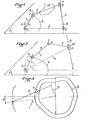
- the four bars 1 to 4 are arranged in the same plane P and are articulated to each other around axes of rotation 5 to 8, orthogonal to said plane.
- the bar 4 is integral with the plane P and the articulation axes 5 and 8 of the said bar to the bars 1 and 3 respectively pass through its ends O to A.
- the bar 2 is articulated to the bars 1 and 3, by means of the articulations 6 and 7 respectively, passing through the ends C and B of said bar 2.
- FIG. 2 The mechanism of FIG. 2 is similar to that of FIG. 1, but in this case, only the bar 1 is arranged in the plane P.
- the bars 2 and 3 are situated outside this plane and the articulation axes 6 and 7 are replaced by ball joints 6 'and 7'.
- a fixed bearing 8 ' is provided on the bar 3, outside the plane P.
- the bar 1 is considered as a driving member and rotates around the axis 5 in the plane P, its end C describing a cercke K with center O.
- the points of the solid 3 describe circular trajectories around of the axis 8.
- the points of the solid 2, except the points C and B, describe closed closed trajectories, when the motor member 1 rotates around its axis 5.
- Such trajectories are plane in the case of mechanism of Figure 1 and are curves of space in the case of the mechanism of Figure 2.
- the correction device comprises a closed cam 10, surrounding the point 0 and cooperating with a cam follower 11, for example a roller.
- the roller 11 is mounted on a crank 12, the crank pin 13 of which rotates around the joint O.
- the "variable bar is formed by the line OC joining the joint O to the free end C of the crank 12, on which the bar 2 is articulated (not shown in FIG. 3).
- the joint C follows a curve (T), which allows the point M of the solid 2 to follow a trajectory of desired shape.
- the follower 11 is integral with a rod 14 of fixed length, capable of sliding in a sleeve 15 rotating around the point O.
- the follower 11 is integral with a rod 16 of fixed length and with an elastic device for example composed of two elastic blades 17 and 18, capable of turning around the point O.
- the cam 10 and the trajectory T can be determined by calculation.
- it is often easier to impose at point M to describe the desired trajectory to experimentally determine the trajectory T and the cam 10.
- the mechanism is produced in full size and the roller 11 can be replaced by a strawberry of the same diameter. This cutter therefore machines the profile of the cam 10. Then, by replacing the cutter with the roller 11, it is certain that point C describes the corrected circular trajectory T and that point M describes the desired trajectory.
- FIG. 6 there is illustrated the mechanism according to the invention capable of communicating to a gripping member not shown, but fixed at point M, a closed trajectory R in the form of L, for example for gripping a workpiece on a press in view of depositing it outside of it or vice versa, positioning one or more parts on a press.
- This mechanism comprises a solid motor end 1 ′, for example similar to that of FIG. 4, that is to say comprising a bar 14 ′ of fixed length, sliding in a sleeve 15 ′ rotating around a joint 0 1 , this sliding during rotation being guided by the cooperation of a roller 11 and a cam 10.
- a solid C 1 B 1 M 1 which with a solid B 2 M 2 and a solid 19, forms the intermediate solid 2'.
- the segment B 2 M 2 is parallel to B 1 M 1 and of the same length, so that B 1 M 1 B 2 M 2 forms a first parallelogram.
- the solid 19 which carries the point M describing the trajectory R is articulated to this first parallelogram in M 1 and M 2 .
- the end solid 3 ' is formed by two parallel bars A 3 B 3 and A 4 B 4 of the same length, articulated at fixed points A 3 and A 4 . They form a second deformable parallelogram.
- deformable parallelograms B 1 M 2 B 2 M 2 and A 3 B 3 A 4 B 4 are articulated to each other in B 1 B 2 B 3 and B 4 , the sides B 1 B 2 (parallel to M 1 M 2 ) and B 3 B 4 (parallel to A 3 A 4 ) forming the diagonals of the parallelogram B i B 2 B 3 B 4 .
Landscapes
- Engineering & Computer Science (AREA)
- General Engineering & Computer Science (AREA)
- Mechanical Engineering (AREA)
- Transmission Devices (AREA)
- Bending Of Plates, Rods, And Pipes (AREA)
Claims (5)
Applications Claiming Priority (2)
| Application Number | Priority Date | Filing Date | Title |
|---|---|---|---|
| FR7828688 | 1978-10-06 | ||
| FR7828688A FR2437943A1 (fr) | 1978-10-06 | 1978-10-06 | Procede et mecanisme pour l'obtention d'une trajectoire fermee de forme desiree |
Publications (2)
| Publication Number | Publication Date |
|---|---|
| EP0010476A1 EP0010476A1 (de) | 1980-04-30 |
| EP0010476B1 true EP0010476B1 (de) | 1982-05-19 |
Family
ID=9213455
Family Applications (1)
| Application Number | Title | Priority Date | Filing Date |
|---|---|---|---|
| EP19790400706 Expired EP0010476B1 (de) | 1978-10-06 | 1979-10-05 | Vorrichtung zur Erzeugung einer geschlossenen Bahn gewünschter Form |
Country Status (3)
| Country | Link |
|---|---|
| EP (1) | EP0010476B1 (de) |
| DE (1) | DE2962906D1 (de) |
| FR (1) | FR2437943A1 (de) |
Families Citing this family (5)
| Publication number | Priority date | Publication date | Assignee | Title |
|---|---|---|---|---|
| US4527446A (en) * | 1982-03-26 | 1985-07-09 | U.S. Automation Company | Cam-actuated robotic manipulator system |
| CN104002594B (zh) * | 2014-04-28 | 2016-03-09 | 江汉大学 | 凸轮轮廓曲线绘图仪 |
| CN104002593B (zh) * | 2014-04-28 | 2016-02-17 | 江汉大学 | 凸轮轮廓曲线绘图仪 |
| CN106956538B (zh) * | 2017-04-27 | 2018-09-04 | 钦州学院 | 双功能式凸轮轨迹绘图仪 |
| CN107747616B (zh) * | 2017-11-01 | 2023-12-12 | 贵州岑祥资源科技有限责任公司 | 一种用于废旧铅酸蓄电池回收的六连杆翻转上线机构 |
-
1978
- 1978-10-06 FR FR7828688A patent/FR2437943A1/fr active Granted
-
1979
- 1979-10-05 EP EP19790400706 patent/EP0010476B1/de not_active Expired
- 1979-10-05 DE DE7979400706T patent/DE2962906D1/de not_active Expired
Also Published As
| Publication number | Publication date |
|---|---|
| DE2962906D1 (en) | 1982-07-08 |
| FR2437943A1 (fr) | 1980-04-30 |
| EP0010476A1 (de) | 1980-04-30 |
| FR2437943B1 (de) | 1983-10-21 |
Similar Documents
| Publication | Publication Date | Title |
|---|---|---|
| BE898154A (fr) | Manipuleur pour positionner des pièces à usiner ou d'autres charges. | |
| FR2467060A1 (fr) | Robot industriel du type articule | |
| EP0074882A2 (de) | Orientierbares Handgelenk mit drei Rotationsachsen für Industrieroboter | |
| EP0147301B1 (de) | Bewegungs-Korrekturkopf mit sechs Freiheitsgraden | |
| FR2521055A1 (fr) | Robot industriel | |
| EP0205376B1 (de) | Schwenkkopf für Industrieroboter und mit einem derartigen Kopf ausgestatteter Roboter | |
| EP0494565A1 (de) | Vorrichtung zum Bewegen eines Objektes auf eine translatorische Weise im Raum, insbesondere für einen mechanischen Roboter | |
| FR2578472A1 (fr) | Perfectionnements aux robots industriels du type a structure spherique | |
| FR2460762A1 (fr) | Dispositif pour la commande de l'orientation d'un outil ou d'un element analogue par rapport a une piece | |
| FR2507520A1 (fr) | Pince pour dispositif de levage destine a la manutention de pieces | |
| EP0010476B1 (de) | Vorrichtung zur Erzeugung einer geschlossenen Bahn gewünschter Form | |
| FR2763786A1 (fr) | Machine robotisee pourvue d'au moins un bras a pantographe symetrique, par exemple pour la recolte de fruits ou le tri d'objets divers | |
| EP0190957A1 (de) | Aus zwei elastisch miteinander verbundenen Teilen bestehender Werkzeughalter, z.B. für Roboter | |
| FR2532388A1 (fr) | Tringlerie mecanique pour deplacement rectiligne | |
| FR2491380A1 (fr) | Robot manipulateur, notamment pour le positionnement automatique de pieces a usiner | |
| FR2593106A1 (fr) | Dispositif de deplacement d'un outil ou analogue en porte-a-faux, notamment autour d'un objet. | |
| FR2562459A1 (fr) | Bras de manipulation modulaire | |
| FR2543470A1 (fr) | Installation de transfert a mecanisme asservi de commande de la rotation des pinces de transfert | |
| FR2494618A1 (fr) | Bras pour un manipulateur a commande programmee | |
| FR2539346A1 (fr) | Dispositif manipulateur automatique articule notamment pour le soudage a l'arc | |
| FR2684601A1 (fr) | Dispositif de pliage pour machines rotatives a imprimer. | |
| FR2498379A1 (fr) | Dispositif d'orientation selon deux axes orthogonaux, utilisation dans une antenne hyperfrequence et antenne hyperfrequence comportant un tel dispositif | |
| FR2610859A1 (fr) | Robot a plusieurs bras, equipes de mecanismes de coordination des mouvements de ces bras | |
| FR2537247A1 (fr) | Dispositif correcteur anti-vissage, pour un vireur de chaudronnerie | |
| FR2723545A1 (fr) | Poignee articulee pour la main de travail d'un robot |
Legal Events
| Date | Code | Title | Description |
|---|---|---|---|
| PUAI | Public reference made under article 153(3) epc to a published international application that has entered the european phase |
Free format text: ORIGINAL CODE: 0009012 |
|
| AK | Designated contracting states |
Designated state(s): CH DE GB IT SE |
|
| 17P | Request for examination filed | ||
| ITF | It: translation for a ep patent filed | ||
| GRAA | (expected) grant |
Free format text: ORIGINAL CODE: 0009210 |
|
| AK | Designated contracting states |
Designated state(s): CH DE GB IT SE |
|
| REF | Corresponds to: |
Ref document number: 2962906 Country of ref document: DE Date of ref document: 19820708 |
|
| PGFP | Annual fee paid to national office [announced via postgrant information from national office to epo] |
Ref country code: CH Payment date: 19841001 Year of fee payment: 6 |
|
| PGFP | Annual fee paid to national office [announced via postgrant information from national office to epo] |
Ref country code: DE Payment date: 19841011 Year of fee payment: 6 |
|
| PGFP | Annual fee paid to national office [announced via postgrant information from national office to epo] |
Ref country code: SE Payment date: 19841231 Year of fee payment: 6 |
|
| PG25 | Lapsed in a contracting state [announced via postgrant information from national office to epo] |
Ref country code: SE Effective date: 19851006 |
|
| PG25 | Lapsed in a contracting state [announced via postgrant information from national office to epo] |
Ref country code: CH Effective date: 19851031 |
|
| GBPC | Gb: european patent ceased through non-payment of renewal fee | ||
| REG | Reference to a national code |
Ref country code: CH Ref legal event code: PL |
|
| PG25 | Lapsed in a contracting state [announced via postgrant information from national office to epo] |
Ref country code: DE Effective date: 19860701 |
|
| PG25 | Lapsed in a contracting state [announced via postgrant information from national office to epo] |
Ref country code: GB Effective date: 19881118 |
|
| EUG | Se: european patent has lapsed |
Ref document number: 79400706.2 Effective date: 19860730 |
|
| PLBE | No opposition filed within time limit |
Free format text: ORIGINAL CODE: 0009261 |
|
| STAA | Information on the status of an ep patent application or granted ep patent |
Free format text: STATUS: NO OPPOSITION FILED WITHIN TIME LIMIT |