EP0010337A1 - Anlage zur Entnahme und Reinigung von Wasser und Abwasser - Google Patents
Anlage zur Entnahme und Reinigung von Wasser und Abwasser Download PDFInfo
- Publication number
- EP0010337A1 EP0010337A1 EP79200597A EP79200597A EP0010337A1 EP 0010337 A1 EP0010337 A1 EP 0010337A1 EP 79200597 A EP79200597 A EP 79200597A EP 79200597 A EP79200597 A EP 79200597A EP 0010337 A1 EP0010337 A1 EP 0010337A1
- Authority
- EP
- European Patent Office
- Prior art keywords
- water
- installation according
- compartment
- effluents
- pump
- Prior art date
- Legal status (The legal status is an assumption and is not a legal conclusion. Google has not performed a legal analysis and makes no representation as to the accuracy of the status listed.)
- Withdrawn
Links
- XLYOFNOQVPJJNP-UHFFFAOYSA-N water Substances O XLYOFNOQVPJJNP-UHFFFAOYSA-N 0.000 title claims abstract description 91
- 239000002351 wastewater Substances 0.000 title 1
- 238000009434 installation Methods 0.000 claims abstract description 65
- 238000011282 treatment Methods 0.000 claims abstract description 36
- 238000000746 purification Methods 0.000 claims abstract description 18
- 239000000126 substance Substances 0.000 claims abstract description 17
- 238000010908 decantation Methods 0.000 claims abstract description 6
- 239000003153 chemical reaction reagent Substances 0.000 claims description 31
- 239000000243 solution Substances 0.000 claims description 18
- 239000000725 suspension Substances 0.000 claims description 16
- 239000007788 liquid Substances 0.000 claims description 12
- 239000002244 precipitate Substances 0.000 claims description 11
- 239000002245 particle Substances 0.000 claims description 10
- 238000005273 aeration Methods 0.000 claims description 9
- 238000002347 injection Methods 0.000 claims description 8
- 239000007924 injection Substances 0.000 claims description 8
- 239000003643 water by type Substances 0.000 claims description 7
- 238000006243 chemical reaction Methods 0.000 claims description 6
- 239000012530 fluid Substances 0.000 claims description 6
- 239000000376 reactant Substances 0.000 claims description 5
- 239000010802 sludge Substances 0.000 claims description 5
- 238000009423 ventilation Methods 0.000 claims description 4
- 230000003750 conditioning effect Effects 0.000 claims description 3
- 238000011109 contamination Methods 0.000 claims description 3
- 238000011084 recovery Methods 0.000 claims description 3
- 231100000331 toxic Toxicity 0.000 claims description 3
- 230000002588 toxic effect Effects 0.000 claims description 3
- 238000005189 flocculation Methods 0.000 claims description 2
- 230000016615 flocculation Effects 0.000 claims description 2
- 230000005484 gravity Effects 0.000 claims description 2
- 238000007654 immersion Methods 0.000 claims description 2
- 238000005192 partition Methods 0.000 claims description 2
- 230000035484 reaction time Effects 0.000 claims description 2
- 230000000630 rising effect Effects 0.000 claims description 2
- 230000004308 accommodation Effects 0.000 claims 1
- 238000004806 packaging method and process Methods 0.000 claims 1
- 238000002360 preparation method Methods 0.000 claims 1
- 239000008213 purified water Substances 0.000 claims 1
- 238000011144 upstream manufacturing Methods 0.000 claims 1
- OSVXSBDYLRYLIG-UHFFFAOYSA-N dioxidochlorine(.) Chemical compound O=Cl=O OSVXSBDYLRYLIG-UHFFFAOYSA-N 0.000 description 6
- 239000007789 gas Substances 0.000 description 5
- 238000000926 separation method Methods 0.000 description 5
- RAHZWNYVWXNFOC-UHFFFAOYSA-N Sulphur dioxide Chemical compound O=S=O RAHZWNYVWXNFOC-UHFFFAOYSA-N 0.000 description 4
- WQYVRQLZKVEZGA-UHFFFAOYSA-N hypochlorite Chemical compound Cl[O-] WQYVRQLZKVEZGA-UHFFFAOYSA-N 0.000 description 4
- 238000004519 manufacturing process Methods 0.000 description 4
- 239000000047 product Substances 0.000 description 4
- ZAMOUSCENKQFHK-UHFFFAOYSA-N Chlorine atom Chemical compound [Cl] ZAMOUSCENKQFHK-UHFFFAOYSA-N 0.000 description 3
- 239000004155 Chlorine dioxide Substances 0.000 description 3
- 241001465754 Metazoa Species 0.000 description 3
- CBENFWSGALASAD-UHFFFAOYSA-N Ozone Chemical compound [O-][O+]=O CBENFWSGALASAD-UHFFFAOYSA-N 0.000 description 3
- 238000009825 accumulation Methods 0.000 description 3
- 235000019398 chlorine dioxide Nutrition 0.000 description 3
- 229940082150 encore Drugs 0.000 description 3
- 238000001914 filtration Methods 0.000 description 3
- 239000000463 material Substances 0.000 description 3
- 238000005070 sampling Methods 0.000 description 3
- 239000007787 solid Substances 0.000 description 3
- WKBOTKDWSSQWDR-UHFFFAOYSA-N Bromine atom Chemical compound [Br] WKBOTKDWSSQWDR-UHFFFAOYSA-N 0.000 description 2
- CURLTUGMZLYLDI-UHFFFAOYSA-N Carbon dioxide Chemical compound O=C=O CURLTUGMZLYLDI-UHFFFAOYSA-N 0.000 description 2
- MHAJPDPJQMAIIY-UHFFFAOYSA-N Hydrogen peroxide Chemical compound OO MHAJPDPJQMAIIY-UHFFFAOYSA-N 0.000 description 2
- 230000001154 acute effect Effects 0.000 description 2
- 239000003463 adsorbent Substances 0.000 description 2
- 230000008901 benefit Effects 0.000 description 2
- 239000000460 chlorine Substances 0.000 description 2
- 229910052801 chlorine Inorganic materials 0.000 description 2
- 239000004020 conductor Substances 0.000 description 2
- 239000003651 drinking water Substances 0.000 description 2
- 235000020188 drinking water Nutrition 0.000 description 2
- 238000010438 heat treatment Methods 0.000 description 2
- 238000000265 homogenisation Methods 0.000 description 2
- 229930195733 hydrocarbon Natural products 0.000 description 2
- 150000002430 hydrocarbons Chemical class 0.000 description 2
- PNDPGZBMCMUPRI-UHFFFAOYSA-N iodine Chemical compound II PNDPGZBMCMUPRI-UHFFFAOYSA-N 0.000 description 2
- 230000004048 modification Effects 0.000 description 2
- 238000012986 modification Methods 0.000 description 2
- 238000007873 sieving Methods 0.000 description 2
- 238000004659 sterilization and disinfection Methods 0.000 description 2
- 241001415961 Gaviidae Species 0.000 description 1
- 241001080024 Telles Species 0.000 description 1
- 230000000844 anti-bacterial effect Effects 0.000 description 1
- 230000001174 ascending effect Effects 0.000 description 1
- 230000000721 bacterilogical effect Effects 0.000 description 1
- 230000015572 biosynthetic process Effects 0.000 description 1
- GDTBXPJZTBHREO-UHFFFAOYSA-N bromine Substances BrBr GDTBXPJZTBHREO-UHFFFAOYSA-N 0.000 description 1
- 229910052794 bromium Inorganic materials 0.000 description 1
- 239000001569 carbon dioxide Substances 0.000 description 1
- 229910002092 carbon dioxide Inorganic materials 0.000 description 1
- 230000008859 change Effects 0.000 description 1
- 239000012141 concentrate Substances 0.000 description 1
- 238000001816 cooling Methods 0.000 description 1
- 238000000354 decomposition reaction Methods 0.000 description 1
- 239000006185 dispersion Substances 0.000 description 1
- 238000004090 dissolution Methods 0.000 description 1
- 230000008030 elimination Effects 0.000 description 1
- 238000003379 elimination reaction Methods 0.000 description 1
- 235000021183 entrée Nutrition 0.000 description 1
- 239000003344 environmental pollutant Substances 0.000 description 1
- 239000004744 fabric Substances 0.000 description 1
- 239000007970 homogeneous dispersion Substances 0.000 description 1
- 229910001410 inorganic ion Inorganic materials 0.000 description 1
- 229910052500 inorganic mineral Inorganic materials 0.000 description 1
- 239000003456 ion exchange resin Substances 0.000 description 1
- 229920003303 ion-exchange polymer Polymers 0.000 description 1
- 239000011707 mineral Substances 0.000 description 1
- 238000002156 mixing Methods 0.000 description 1
- 239000000203 mixture Substances 0.000 description 1
- 101150006061 neur gene Proteins 0.000 description 1
- 230000000422 nocturnal effect Effects 0.000 description 1
- 231100000028 nontoxic concentration Toxicity 0.000 description 1
- 239000003921 oil Substances 0.000 description 1
- 239000004033 plastic Substances 0.000 description 1
- 229920003023 plastic Polymers 0.000 description 1
- 231100000719 pollutant Toxicity 0.000 description 1
- 239000002994 raw material Substances 0.000 description 1
- 238000005057 refrigeration Methods 0.000 description 1
- 239000000523 sample Substances 0.000 description 1
- 125000006850 spacer group Chemical group 0.000 description 1
- 230000003068 static effect Effects 0.000 description 1
- 230000001954 sterilising effect Effects 0.000 description 1
- -1 vapors Substances 0.000 description 1
- 230000003253 viricidal effect Effects 0.000 description 1
- 239000002023 wood Substances 0.000 description 1
Images
Classifications
-
- B—PERFORMING OPERATIONS; TRANSPORTING
- B01—PHYSICAL OR CHEMICAL PROCESSES OR APPARATUS IN GENERAL
- B01D—SEPARATION
- B01D21/00—Separation of suspended solid particles from liquids by sedimentation
- B01D21/28—Mechanical auxiliary equipment for acceleration of sedimentation, e.g. by vibrators or the like
- B01D21/283—Settling tanks provided with vibrators
-
- B—PERFORMING OPERATIONS; TRANSPORTING
- B01—PHYSICAL OR CHEMICAL PROCESSES OR APPARATUS IN GENERAL
- B01D—SEPARATION
- B01D21/00—Separation of suspended solid particles from liquids by sedimentation
-
- B—PERFORMING OPERATIONS; TRANSPORTING
- B01—PHYSICAL OR CHEMICAL PROCESSES OR APPARATUS IN GENERAL
- B01D—SEPARATION
- B01D21/00—Separation of suspended solid particles from liquids by sedimentation
- B01D21/003—Sedimentation tanks provided with a plurality of compartments separated by a partition wall
- B01D21/0036—Horizontal partition walls
-
- B—PERFORMING OPERATIONS; TRANSPORTING
- B01—PHYSICAL OR CHEMICAL PROCESSES OR APPARATUS IN GENERAL
- B01D—SEPARATION
- B01D21/00—Separation of suspended solid particles from liquids by sedimentation
- B01D21/0039—Settling tanks provided with contact surfaces, e.g. baffles, particles
-
- B—PERFORMING OPERATIONS; TRANSPORTING
- B01—PHYSICAL OR CHEMICAL PROCESSES OR APPARATUS IN GENERAL
- B01D—SEPARATION
- B01D21/00—Separation of suspended solid particles from liquids by sedimentation
- B01D21/0039—Settling tanks provided with contact surfaces, e.g. baffles, particles
- B01D21/0045—Plurality of essentially parallel plates
-
- B—PERFORMING OPERATIONS; TRANSPORTING
- B01—PHYSICAL OR CHEMICAL PROCESSES OR APPARATUS IN GENERAL
- B01D—SEPARATION
- B01D21/00—Separation of suspended solid particles from liquids by sedimentation
- B01D21/01—Separation of suspended solid particles from liquids by sedimentation using flocculating agents
-
- B—PERFORMING OPERATIONS; TRANSPORTING
- B01—PHYSICAL OR CHEMICAL PROCESSES OR APPARATUS IN GENERAL
- B01D—SEPARATION
- B01D21/00—Separation of suspended solid particles from liquids by sedimentation
- B01D21/02—Settling tanks with single outlets for the separated liquid
-
- B—PERFORMING OPERATIONS; TRANSPORTING
- B01—PHYSICAL OR CHEMICAL PROCESSES OR APPARATUS IN GENERAL
- B01D—SEPARATION
- B01D21/00—Separation of suspended solid particles from liquids by sedimentation
- B01D21/24—Feed or discharge mechanisms for settling tanks
- B01D21/2427—The feed or discharge opening located at a distant position from the side walls
-
- B—PERFORMING OPERATIONS; TRANSPORTING
- B01—PHYSICAL OR CHEMICAL PROCESSES OR APPARATUS IN GENERAL
- B01D—SEPARATION
- B01D21/00—Separation of suspended solid particles from liquids by sedimentation
- B01D21/30—Control equipment
- B01D21/34—Controlling the feed distribution; Controlling the liquid level ; Control of process parameters
-
- C—CHEMISTRY; METALLURGY
- C02—TREATMENT OF WATER, WASTE WATER, SEWAGE, OR SLUDGE
- C02F—TREATMENT OF WATER, WASTE WATER, SEWAGE, OR SLUDGE
- C02F1/00—Treatment of water, waste water, or sewage
- C02F1/52—Treatment of water, waste water, or sewage by flocculation or precipitation of suspended impurities
- C02F1/5281—Installations for water purification using chemical agents
-
- C—CHEMISTRY; METALLURGY
- C02—TREATMENT OF WATER, WASTE WATER, SEWAGE, OR SLUDGE
- C02F—TREATMENT OF WATER, WASTE WATER, SEWAGE, OR SLUDGE
- C02F3/00—Biological treatment of water, waste water, or sewage
- C02F3/02—Aerobic processes
- C02F3/12—Activated sludge processes
- C02F3/1205—Particular type of activated sludge processes
- C02F3/1215—Combinations of activated sludge treatment with precipitation, flocculation, coagulation and separation of phosphates
-
- C—CHEMISTRY; METALLURGY
- C02—TREATMENT OF WATER, WASTE WATER, SEWAGE, OR SLUDGE
- C02F—TREATMENT OF WATER, WASTE WATER, SEWAGE, OR SLUDGE
- C02F3/00—Biological treatment of water, waste water, or sewage
- C02F3/02—Aerobic processes
- C02F3/12—Activated sludge processes
- C02F3/20—Activated sludge processes using diffusers
-
- C—CHEMISTRY; METALLURGY
- C02—TREATMENT OF WATER, WASTE WATER, SEWAGE, OR SLUDGE
- C02F—TREATMENT OF WATER, WASTE WATER, SEWAGE, OR SLUDGE
- C02F9/00—Multistage treatment of water, waste water or sewage
-
- E—FIXED CONSTRUCTIONS
- E03—WATER SUPPLY; SEWERAGE
- E03B—INSTALLATIONS OR METHODS FOR OBTAINING, COLLECTING, OR DISTRIBUTING WATER
- E03B1/00—Methods or layout of installations for water supply
-
- C—CHEMISTRY; METALLURGY
- C02—TREATMENT OF WATER, WASTE WATER, SEWAGE, OR SLUDGE
- C02F—TREATMENT OF WATER, WASTE WATER, SEWAGE, OR SLUDGE
- C02F2201/00—Apparatus for treatment of water, waste water or sewage
- C02F2201/008—Mobile apparatus and plants, e.g. mounted on a vehicle
-
- Y—GENERAL TAGGING OF NEW TECHNOLOGICAL DEVELOPMENTS; GENERAL TAGGING OF CROSS-SECTIONAL TECHNOLOGIES SPANNING OVER SEVERAL SECTIONS OF THE IPC; TECHNICAL SUBJECTS COVERED BY FORMER USPC CROSS-REFERENCE ART COLLECTIONS [XRACs] AND DIGESTS
- Y02—TECHNOLOGIES OR APPLICATIONS FOR MITIGATION OR ADAPTATION AGAINST CLIMATE CHANGE
- Y02W—CLIMATE CHANGE MITIGATION TECHNOLOGIES RELATED TO WASTEWATER TREATMENT OR WASTE MANAGEMENT
- Y02W10/00—Technologies for wastewater treatment
- Y02W10/10—Biological treatment of water, waste water, or sewage
Definitions
- the present invention relates to a compact and simplified installation for sampling and various treatments for the purification of water and aqueous effluents of various origins, preferably mobile, without this latter characteristic being limiting.
- mobile should also be interpreted as transportable.
- the compactness and simplification of the installation also aim to reduce the weight of the whole, when this last factor is important for the means of transport envisaged (plane, boat, land vehicle).
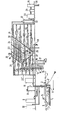
- the installation which is the subject of the present invention is characterized in that it comprises two essential elements, on the one hand a water intake apparatus, in which various physical and chemical treatment operations are carried out and, d 'on the other hand, a more elaborate purification apparatus subject to the intake apparatus, especially with regard to the transfer of the waters or aqueous effluents to be treated, this transfer from the intake to the settling being carried out by means of '' a single pump, whose controlled flow conditions all of the treatments until decantation.
- the water intake apparatus comprises an aeration compartment obtained by the release of compressed air in the form of fine bubbles, the flow rate of injected air being adaptable to the flow rate of the water or effluents to be treated.
- the pump intake is arranged in such a way that it draws water and aqueous effluents through the intake apparatus, allowing their aeration, discharges the water and aqueous effluents towards the elaborate purification apparatus, and allows to carry out a chemical pretreatment with gaseous or liquid reagents by injection of reagents at the entry of water or aqueous effluents into said pump.
- the actual treatment installation according to the invention comprises, in order, a continuous tubular reactor, a settling tank of the accelerated settling type, and one or more filters.
- the continuous tubular reactor consists of a pipe or tube arranged in superposed concentric spirals.
- the decanter is in the form of a prismatic tank surmounting a hopper and comprises a series of compartments, including oblique upper compartments contiguous to each other, the inlet being located in the first of these compartments where the water charged with particles circulates from top to bottom, while the current is upward in the other oblique compartments, a horizontal compartment opening under these oblique compartments and above a lower compartment forming the hopper intended for the evacuation of particles in the form of sludge.
- the installation shown in the drawing comprises a water intake apparatus, consisting of a partially submerged container 1, supported by streams teurs 2 (floating socket).
- the external shape of this container is suitable for its possible use in running water or running effluents, that is to say with a hydrodynamic front so as to allow an easy flow of water and aqueous effluents when they are in motion.
- the anchor point must be such that the tapered shape appears against the current.
- the rear consists of an inclined grid 3, preferably at 45 °, through which the water or the aqueous effluents to be treated enter the floating outlet.
- the layout of the grid at the rear and its inclination are intended to considerably reduce the accumulation of debris on it.
- the size of the meshes of the order of 2 mm, is chosen so that the most diverse objects (wood, leaves, possible animals) do not enter the device.
- the size of the meshes and the inclination of the grid also allow a partial unclogging of the grid by air injected behind the grid (acute angle side). This grid can be double, so that one can unclog one of the two without interrupting the operation of the entire installation.
- the part behind the grid consists of an aeration compartment 4 obtained by the release of compressed air in the form of fine bubbles, by means of porous tubes or plates for example.
- the flow rate of injected air is adaptable to the flow rate of the water or effluents to be treated, so that each liter thereof is aerated by a chosen quantity of air, preferably between 1 and 50 liters.
- the purpose of this air injection is to partially or completely remove volatile substances in solution or in dispersion in water (such as smelly and / or toxic products and / or light hydrocarbons, etc.). This also prevents entry into the device floating substances, such as oils, heavy hydrocarbons, etc.
- the ventilated part therefore begins under the grid and ends at a distance such that the air / water ratio or volume is preferably between 1 and 50.
- the compressed air release system is protected by a grid, which also has the function of better distributing the air bubbles.
- the degree of immersion of the device is such that the open edge of this compartment does not allow re-entry of water that has not passed through the grid 3.
- the edge emerges from about 5 cm to 10 cm above of the surface of the waters or aqueous effluents to be treated.
- the horizontality of the floating socket is adjusted by a mobile counterweight, preferably placed at the top, on the median axis in the direction of the length of the device. It can be constituted by a flashing lantern 5 fitted with its batteries or accumulators, serving as a nocturnal position indicator.
- the ventilation compartment 4 ends with a partition 6 whose height, from the bottom, is such that the air bubbles released cannot enter the last compartment where the submerged intake pump 7 is located.
- this system is in principle not limiting as to the number of solutions. It also allows effective contact between the water or aqueous effluents to be treated and the reagents.
- gaseous reactants such as, for example: chlorine, chlorine dioxide, sulfur dioxide, ozone, etc.
- these can, for example in this way, be introduced into the treatment circuit, under low pressure, when the latter is linked to its production system.
- this type of injection is limited when the flow rate of the gaseous reactant is too large, since there can be a defusing of the pump.
- This system is particularly advantageous for products which can undergo decomposition in metering pumps, such as hydrogen peroxide for example.
- this pump is fitted with a float switch which controls the operation and stopping of one or more pumps and metering pumps, valves, alarms, etc. inserted into the global processing circuit.
- Another characteristic of this pump is to be fixed on a frame itself detachable from the floating outlet.
- the delivery pipe of the pump To this frame are fixed the delivery pipe of the pump, the supply lines for liquid or gaseous reagents.
- the air supply to the ventilation system is fixed to the floating outlet.
- This frame can be placed in a container of cylindrical shape and of low height, screened at its upper part, so that water or aqueous effluents can penetrate through this opening to reach the pump without causing debris and especially of the vase or deposits.
- the intake pump (preferably of the self-priming type), can be placed on firm ground, provided that its suction duct (with or without foot valve) is located at the same place on the floating intake as was the water intake of the submerged pump from the first description.
- the water intake apparatus was immersed in the flow of water or aqueous effluents to be treated but, of course, it can also, according to the invention, be placed on the ground in a tank of a design similar to the floating outlet described above (grids, aeration compartment, pump), but the supply of water or aqueous effluents to said tank is made by means of either a pump submerged and a connecting pipe, either a pump placed on the ground and a connecting pipe, provided that its suction pipe (with strainer and with or without foot valve) submerges in water or the effluent.
- the installation also comprises a purification apparatus, which can be fixed or mobile and which consists of a control and junction panel 11 with the floating outlet 1, a treatment installation proper, and auxiliary apparatus.
- the control panel 11 comprises the various junctions by pipes and flexible wires between the floating outlet, the purification installation itself and the auxiliaries (compressors, generators of gaseous or solution reagents, electrical conductors). It also includes different control systems (adjustable valves, flowmeters, manometers, thermometers and analytical instruments).
- the treatment installation comprises a continuous reactor, a decanter and filters.
- the treatment of water and various aqueous effluents consists mainly of adding reagents in determined quantities depending on the nature and concentration of the pollutant (s), the volume to be treated and the time necessary for the chemical reactions to take place. , in order to obtain a water or an effluent that meets the purification criteria.
- a continuous tubular reactor 12 consisting of a pipe or tube, the dimensions of which are a function of the flow of water to be treated and the total time necessary to carry out all the chemical reactions d purification.
- reagent injection points supplied with dosing pumps with reagent tanks 13 to 17 at different lengths of this pipe.
- chemical and physical purification reactions require sometimes using solid and generally insoluble products, on the other hand, there is formation of precipitates, the design of such a treatment reactor requires a linear speed of the fluid (water or effluents + reactants in solution and / or in suspension + precipitates) such that there is no deposit inside the latter.
- a linear speed of the fluid is therefore imposed between 0.40 and 1 m / sec., Preferably from 0.55 to 0.70 m / sec.
- a treatment total depollution (before the separation of solids / purified liquid) must not last more than thirty to forty-five minutes, without this time being able to constitute a limitation. Obtained for these conditions, given by way of example, the theoretical limit lengths that the tubular reactor can have, ie 720 to 2,700 meters. As other factors must be taken into account, weight, size and cost in particular, it is considered that for these treatment times, the practical flow is of the order of 10 to 15 m3 / hour, especially if there is is transportable facilities.
- the most important problem is the provision of such a length in a compact form and taking into account the implementation of the material constituting the pipe.
- the tubular reactor is arranged in its total length or in sections thereof in one or more containers -, (understood in the broadest sense) preferably stackable.
- containers can be made in any mat-era, provided that the mechanical properties thereof allow.
- This container will preferably be in the form of a double parallelepiped or of a double cylinder or of any double intermediate shape, the concentric elements determining between them the container itself.
- the pipe is wound in contiguous or slightly spaced but parallel spirals from the inner edge of the large parallelepiped or large cylinder (inlet of the fluid opening onto the outer surface) towards the outer edge of the small parallelepiped or small cylinder, then by superposition on a lower spiral from the outer edge of the small parallelepiped or the small cylinder to the inner edge of the large parallelepiped or large cy lindre, so that the end of the reactor or a sec on of the latter can lead to an outer face, preferably on that of the inlet.
- the number of stages is therefore preferably chosen, so that the pipe or tube goes from the outside edge to the inside edge or vice versa.
- the container stacking system saves basic space compared to the system of placing containers side by side.
- the stacking system of the containers makes it possible in fact to obtain a continuous quasi-helical spiral going from the bottom to the top (if one places oneself from the point of view of the water or the effluents to be treated), so that gases or vapors can be more easily removed.
- Each container can contain one or more metering pumps in the free spaces and on the outside faces, there can be the inputs and outputs of reagents for metering pumps, indicator lights, inputs for probes or electrodes, or sensitive elements of instruments control lines which are inserted in the pipe, passages for supply conductors, so that each container can constitute a complete set of treatment.
- a static mixer can also be available after each reagent entry into the pipe.
- the section can also contain air-lifts and / or ejectors and / or ultrasonic generators.
- each container for reasons of weight, mechanical strength, ease of assembly, handling, transport or even to avoid crushing of the pipes if they are made of a flexible material (plastics for example) can only contain a limited number of superposed stages of pipes, especially if the spirals are arranged side by side without support, spacer or frame.
- the above does not exclude the use of these to ensure that this assembly has a certain immobilization of the pipe and also allow refrigeration or heating by fluid external to the pipe.
- another arrangement of the tubular reactor also consists in placing the pipe or tube in superposed concentric spirals, in the same design as that previously described and this in the widest sense, in a support frame, within which the pipe or tube constituting the tubular reactor can be fixed securely by means of fasteners or in notches cut from both vertical and horizontal supports.
- the support frame can contain the metering pumps and the external faces include the same elements as those arranged on the external faces of the containers previously described.
- the decanter has five compartments.
- the closed space above the water level allows the separation of gases, vapors or air from the water for the purpose of evacuation by a pipe 20.
- -Its lower part has inclined plates 21, preferably at 55 ° , on which the flocs brought by the water or the treated effluent slide. In this compartment, the water and the flocs go in the same direction, that is to say from top to bottom.
- the second compartment 22 is a free space in which the water and part of the precipitate flow horizontally.
- the third and fourth compartments 23, 24, placed side by side and also attached to the first, comprise tubes 25 or inclined plates, preferably at 55 °, in which the particles entrained by the rising current of water are deposited on those -this then descend in the opposite direction to the current towards the second compartment 22 and the fifth compartment 26
- the water speed is at least two times lower than that of the first compartment.
- an ascending speed of 1 mm / sec will be chosen.
- the fifth compartment 26 which is located under compartments one, three, qua-cre and two aims to concentrate by its pyramidal shape the particles from the other compartments.
- This fifth compartment is separated from the others by an assembly of vertical thin-walled tubes 27 2 cm to 5 cm in diameter, 10 cm long and joined to one another. These tubes can have an inclination of 0 ° to 60 °, angle formed by the direction of circulation of the water and the wall of the tubes (acute angle).
- a curved plate 22 ' partially covering these tubes 27, communicates a horizontal movement to the water.
- the purpose of the vertical, thin-walled tubes is, while letting the flocs descend into the fifth compartment, to create a zone without eddies, thus avoiding the upward entrainment of the already decanted flocs.
- a tube preferably connected to an adjustable flow pump 28 discharges the sludge formed by the flocs or the precipitate outside.
- one or more mechanical or electromagnetic vibrators can be arranged on the outer walls of the fifth compartment, although the anterior solution (vibrations within the suspension) is preferable, especially if it is a metallic decanter whose walls are welded.
- the level of this plate is preferably located a few centimeters below the level of the inlet tubing of the decanter.
- the water, freed for the most part from solid matter, is brought by gravity from the outlet of the decanter into a recovery tank 31, where the pump 32 is located or the intake of the pump supplying the filters 33.
- This tank is provided with a overflow and drain hose.
- the water level is controlled by two sensors, high level and low level, to which the operation of the pump supplying the filters is controlled.
- the useful volume of this tank is calculated in such a way that, taking into account the water outlet flow rate from the decanter, the pump does not switch on and off only a few times per hour of operation.
- the pipe joining the pump to the filters will be fitted with a non-return valve and a pressure gauge, preferably with contact, so as to indicate (lamp or acoustic signal) the set pressure limit of the filter (s) or the degree of clogging of this or these.
- the solid-liquid separation is refined by means of a filter or several filters arranged in parallel, the main characteristic of which is the filtering raw material (fabric, reinforced paper) is its porosity of 50 to 1 micron, preferably 10 to 5 microns.
- this filter 33 will be followed by bacteriological filters 34, the main characteristic of which is the porosity of 1 to 0.1 micron and preferably from 0.4 to 0 , 2 micron.
- the arrival of the reagents takes place at the top of the cone, and the exit of the reagents tangentially to the cylindrical part of the tank or the base of the cone.
- This arrangement of the tangential grip generates a vortex movement within the solution or suspension. Due to the arrival of solutions or suspensions in the center of the bottom of the tank, there is an energetic mixing of the solution or suspensions. In fact, especially in the case of suspensions, the particles launched by the current towards the surface of the solution or suspension tend to descend along the walls, where they again reach the central jet. They are therefore dragged back to the surface.
- the solution or suspension intake tubing intended for supplying the metering pumps is placed perpendicular to the wall of the cone of the tank, preferably between the top of the cone and the recovery tubing of the circulation pump.
Landscapes
- Chemical & Material Sciences (AREA)
- Chemical Kinetics & Catalysis (AREA)
- Life Sciences & Earth Sciences (AREA)
- Engineering & Computer Science (AREA)
- Water Supply & Treatment (AREA)
- Hydrology & Water Resources (AREA)
- Organic Chemistry (AREA)
- Environmental & Geological Engineering (AREA)
- Microbiology (AREA)
- Biodiversity & Conservation Biology (AREA)
- Analytical Chemistry (AREA)
- General Chemical & Material Sciences (AREA)
- Health & Medical Sciences (AREA)
- Public Health (AREA)
- Treatment Of Water By Oxidation Or Reduction (AREA)
Applications Claiming Priority (2)
| Application Number | Priority Date | Filing Date | Title |
|---|---|---|---|
| BE6046646A BE871512A (fr) | 1978-10-24 | 1978-10-24 | Installation de prelevement et de traitement d'epuration d'eaux et d'effluents aqueux. |
| BE6046646 | 1978-10-24 |
Publications (1)
| Publication Number | Publication Date |
|---|---|
| EP0010337A1 true EP0010337A1 (de) | 1980-04-30 |
Family
ID=3874800
Family Applications (1)
| Application Number | Title | Priority Date | Filing Date |
|---|---|---|---|
| EP79200597A Withdrawn EP0010337A1 (de) | 1978-10-24 | 1979-10-18 | Anlage zur Entnahme und Reinigung von Wasser und Abwasser |
Country Status (3)
| Country | Link |
|---|---|
| US (1) | US4324656A (de) |
| EP (1) | EP0010337A1 (de) |
| BE (1) | BE871512A (de) |
Cited By (3)
| Publication number | Priority date | Publication date | Assignee | Title |
|---|---|---|---|---|
| FR2571354A1 (fr) * | 1984-10-08 | 1986-04-11 | Liszak Joseph | Installation pour le traitement de liquides, notamment d'eaux, par floculation, puis filtration |
| EP0152666A3 (en) * | 1984-02-03 | 1986-05-14 | Continental Mfg & Sales Inc | Method and apparatus for the clarification of sewage and other wastes |
| FR2573062A1 (fr) * | 1984-11-13 | 1986-05-16 | Liszak Joseph | Installation pour le traitement de liquides, notamment d'eau, comprenant un filtre regenerable et un compresseur d'air |
Families Citing this family (13)
| Publication number | Priority date | Publication date | Assignee | Title |
|---|---|---|---|---|
| JPS6038007A (ja) * | 1983-08-11 | 1985-02-27 | Yks Co Ltd | 船舶用油水分離装置 |
| US4997557A (en) * | 1989-05-19 | 1991-03-05 | Aqua-Aerobic Systems, Inc. | Floating, mixing, aerating and decanting unit |
| US5266196A (en) * | 1991-07-19 | 1993-11-30 | Mountain Safety Research, Inc. | Water filter |
| US8337706B2 (en) * | 2007-10-14 | 2012-12-25 | 1612017 Alberta Ltd. | Solids removal system and method |
| US9192879B2 (en) | 2007-10-14 | 2015-11-24 | 1612017 Alberta Ltd. | Solids removal system and method |
| US20090095690A1 (en) * | 2007-10-14 | 2009-04-16 | Mccabe Derald L | Solids removal system and method |
| US8691097B2 (en) | 2007-10-14 | 2014-04-08 | 1612017 Alberta Ltd. | Solids removal system and method |
| CA2686836C (en) | 2008-12-01 | 2017-04-11 | International Water-Guard Industries, Inc. | Water distribution system with dual use water treatment unit |
| US8317036B2 (en) * | 2010-05-11 | 2012-11-27 | Roberts Marketing De, Inc. | Apparatus and method for removing impurities from water or wastewater |
| CN102535580B (zh) * | 2012-03-06 | 2013-08-14 | 西安建筑科技大学 | 预净化选择性取水构筑物 |
| US9149741B2 (en) * | 2012-09-24 | 2015-10-06 | Unipure Corporation | Mobile fluid treatment system and associated apparatus |
| CN106946389A (zh) * | 2017-03-31 | 2017-07-14 | 陈来胜 | 一种污水处理装置 |
| CN111115907B (zh) * | 2020-01-20 | 2022-03-11 | 广州市汇鹏建设有限公司 | 一种海绵城市雨水处理方法 |
Citations (8)
| Publication number | Priority date | Publication date | Assignee | Title |
|---|---|---|---|---|
| FR380333A (fr) * | 1907-07-29 | 1907-12-05 | Tadeusz Lewicki | Appareil pour débarrasser les liquides et en particulier les eaux de vidange des matières en suspension |
| FR1575592A (de) * | 1967-02-21 | 1969-07-25 | ||
| US3607735A (en) * | 1969-07-02 | 1971-09-21 | Air Reduction | System for treatment of secondary sewage |
| US3774768A (en) * | 1972-08-16 | 1973-11-27 | Westinghouse Electric Corp | Apparatus for treating industrial and domestic waste waters |
| GB1346596A (en) * | 1971-05-20 | 1974-02-13 | Allied Colloids Mfg | Flocculating method |
| FR2255262A1 (de) * | 1973-12-20 | 1975-07-18 | Waltec Ind Ltd | |
| US4076615A (en) * | 1974-02-27 | 1978-02-28 | Battelle Pacific N. W. Laboratories | Process and system for treating waste water |
| FR2387465A1 (fr) * | 1977-04-15 | 1978-11-10 | Lelievre Maurice | Predigesteurs-regulateur d'eaux-vannes et eaux usees domestiques pour stations d'epuration de maisons individuelles et de petites collectivites |
Family Cites Families (12)
| Publication number | Priority date | Publication date | Assignee | Title |
|---|---|---|---|---|
| US2190596A (en) * | 1940-02-13 | Flocculation process and apparatus | ||
| US2778499A (en) * | 1952-09-16 | 1957-01-22 | Coal Industry Patents Ltd | Method of froth flotation |
| US3441956A (en) * | 1967-01-23 | 1969-04-29 | Willard Farnham | Liquid treatment method and apparatus |
| US3579554A (en) * | 1968-10-31 | 1971-05-18 | Du Pont | Desludging tel with oxygenated water |
| US3716485A (en) * | 1971-01-11 | 1973-02-13 | Ayteks International Corp | Process and apparatus for destroying hexavalent chromium in solution |
| SE356288B (de) * | 1971-04-29 | 1973-05-21 | Gustavsbergs Fabriker Ab | |
| US4113619A (en) * | 1973-03-22 | 1978-09-12 | Arrington Co., Inc. | Waste fluid treatment system |
| US3893656A (en) * | 1973-08-20 | 1975-07-08 | Chemfix Inc | Mobile unit for treating liquid waste |
| US3948774A (en) * | 1973-10-05 | 1976-04-06 | Environment Improvement, Inc. | Water purification process and apparatus |
| DE2656362A1 (de) * | 1976-12-13 | 1978-06-15 | Rolf Flach | Verfahren und vorrichtung zum klaeren von abwaessern |
| US4200534A (en) * | 1978-06-05 | 1980-04-29 | Ferdinand Besik | Apparatus for renovation of sanitary waters |
| US4190539A (en) * | 1978-08-16 | 1980-02-26 | Ferdinand Besik | Apparatus for on-site renovation of sanitary waters |
-
1978
- 1978-10-24 BE BE6046646A patent/BE871512A/xx not_active IP Right Cessation
-
1979
- 1979-10-11 US US06/084,032 patent/US4324656A/en not_active Expired - Lifetime
- 1979-10-18 EP EP79200597A patent/EP0010337A1/de not_active Withdrawn
Patent Citations (8)
| Publication number | Priority date | Publication date | Assignee | Title |
|---|---|---|---|---|
| FR380333A (fr) * | 1907-07-29 | 1907-12-05 | Tadeusz Lewicki | Appareil pour débarrasser les liquides et en particulier les eaux de vidange des matières en suspension |
| FR1575592A (de) * | 1967-02-21 | 1969-07-25 | ||
| US3607735A (en) * | 1969-07-02 | 1971-09-21 | Air Reduction | System for treatment of secondary sewage |
| GB1346596A (en) * | 1971-05-20 | 1974-02-13 | Allied Colloids Mfg | Flocculating method |
| US3774768A (en) * | 1972-08-16 | 1973-11-27 | Westinghouse Electric Corp | Apparatus for treating industrial and domestic waste waters |
| FR2255262A1 (de) * | 1973-12-20 | 1975-07-18 | Waltec Ind Ltd | |
| US4076615A (en) * | 1974-02-27 | 1978-02-28 | Battelle Pacific N. W. Laboratories | Process and system for treating waste water |
| FR2387465A1 (fr) * | 1977-04-15 | 1978-11-10 | Lelievre Maurice | Predigesteurs-regulateur d'eaux-vannes et eaux usees domestiques pour stations d'epuration de maisons individuelles et de petites collectivites |
Non-Patent Citations (1)
| Title |
|---|
| COAL AGE, Vol. 82, No. 1, Janvier 1977, New York (US) N.P. CHIRONIS: "Thickener with novel configuration saves space and costs in prep plants, pages 114-118. * |
Cited By (3)
| Publication number | Priority date | Publication date | Assignee | Title |
|---|---|---|---|---|
| EP0152666A3 (en) * | 1984-02-03 | 1986-05-14 | Continental Mfg & Sales Inc | Method and apparatus for the clarification of sewage and other wastes |
| FR2571354A1 (fr) * | 1984-10-08 | 1986-04-11 | Liszak Joseph | Installation pour le traitement de liquides, notamment d'eaux, par floculation, puis filtration |
| FR2573062A1 (fr) * | 1984-11-13 | 1986-05-16 | Liszak Joseph | Installation pour le traitement de liquides, notamment d'eau, comprenant un filtre regenerable et un compresseur d'air |
Also Published As
| Publication number | Publication date |
|---|---|
| BE871512A (fr) | 1979-04-24 |
| US4324656A (en) | 1982-04-13 |
Similar Documents
| Publication | Publication Date | Title |
|---|---|---|
| FR2512802A1 (fr) | Appareil et procede de clarification d'eau par utilisation combinee de processus de flottation et de filtration | |
| EP0010337A1 (de) | Anlage zur Entnahme und Reinigung von Wasser und Abwasser | |
| US4367145A (en) | Portable water clarifier | |
| FR2501054A1 (fr) | Procede et appareil pour nettoyer des bassins | |
| KR101297293B1 (ko) | 스컴 농축 기능을 구비한 부상 분리 장치 | |
| RU2431610C2 (ru) | Комплексный способ безреагентной очистки сточных вод и брикетирования ила | |
| WO2012163308A2 (es) | Planta modular integrada, multifuncional para separar sólidos, aceites e hidrocarburos y tratar las aguas residuales industriales petroleras | |
| FR2583406A1 (fr) | Epurateur biologique a membrane du type a ecoulement vers le bas pour le traitement biologique de l'eau usee. | |
| US20090178968A1 (en) | Water treatment apparatus | |
| US4224155A (en) | Sewage treatment apparatus | |
| US3984322A (en) | Sewage treatment apparatus | |
| FR2690682A1 (fr) | Dispositif pour la séparation par écumage de composants essentiellement organiques de l'eau. | |
| CA2412487A1 (fr) | Dispositif de purification d'effluent | |
| FR2571354A1 (fr) | Installation pour le traitement de liquides, notamment d'eaux, par floculation, puis filtration | |
| EP3026022A1 (de) | Mikro-station zur biologischen reinigung | |
| EP0174232B1 (de) | Verfahren zum Klären einer feststoffbeladenen Flüssigkeit mittels eines Schlammbettes | |
| EP0237391B1 (de) | Verfahren und Vorrichtung für die Abwasserbehandlung | |
| FR2564821A1 (fr) | Procede de deshydratation des boues et installation de ce procede | |
| FR3068614A1 (fr) | Installation pour le traitement des eaux par floculation lestee et decantation integrees et procede correspondant | |
| EP1982962A1 (de) | Verfahren zur Umwandlung einer Klärgrube in eine biologische Rückgewinnungsstation von Brauchwasser | |
| ES2239872B1 (es) | Aparato para la depuracion de aguas residuales. | |
| CN2560638Y (zh) | 水净化装置及移动型水净化装置 | |
| SE520338C2 (sv) | Förfarande och anordning för rening av dag- eller spillvatten | |
| BE1000938A3 (fr) | Melangeur-decanteur tubulaire a plusieurs etages, destine a etre mis en oeuvre dans l'extraction liquide-liquide a contre-courant. | |
| FR2484272A1 (fr) | Dispositif d'epuration d'effluents liquides par decantation et filtration |
Legal Events
| Date | Code | Title | Description |
|---|---|---|---|
| PUAI | Public reference made under article 153(3) epc to a published international application that has entered the european phase |
Free format text: ORIGINAL CODE: 0009012 |
|
| AK | Designated contracting states |
Designated state(s): AT CH DE FR GB IT LU NL SE |
|
| ITCL | It: translation for ep claims filed |
Representative=s name: UFFICIO TECNICO ING. A. MANNUCCI |
|
| TCAT | At: translation of patent claims filed | ||
| DET | De: translation of patent claims | ||
| 17P | Request for examination filed |
Effective date: 19801016 |
|
| STAA | Information on the status of an ep patent application or granted ep patent |
Free format text: STATUS: THE APPLICATION IS DEEMED TO BE WITHDRAWN |
|
| 18D | Application deemed to be withdrawn |
Effective date: 19820828 |