EP0010337A1 - A plant for gathering and purifying water and waste water - Google Patents
A plant for gathering and purifying water and waste water Download PDFInfo
- Publication number
- EP0010337A1 EP0010337A1 EP79200597A EP79200597A EP0010337A1 EP 0010337 A1 EP0010337 A1 EP 0010337A1 EP 79200597 A EP79200597 A EP 79200597A EP 79200597 A EP79200597 A EP 79200597A EP 0010337 A1 EP0010337 A1 EP 0010337A1
- Authority
- EP
- European Patent Office
- Prior art keywords
- water
- installation according
- compartment
- effluents
- pump
- Prior art date
- Legal status (The legal status is an assumption and is not a legal conclusion. Google has not performed a legal analysis and makes no representation as to the accuracy of the status listed.)
- Withdrawn
Links
Images
Classifications
-
- B—PERFORMING OPERATIONS; TRANSPORTING
- B01—PHYSICAL OR CHEMICAL PROCESSES OR APPARATUS IN GENERAL
- B01D—SEPARATION
- B01D21/00—Separation of suspended solid particles from liquids by sedimentation
- B01D21/28—Mechanical auxiliary equipment for acceleration of sedimentation, e.g. by vibrators or the like
- B01D21/283—Settling tanks provided with vibrators
-
- B—PERFORMING OPERATIONS; TRANSPORTING
- B01—PHYSICAL OR CHEMICAL PROCESSES OR APPARATUS IN GENERAL
- B01D—SEPARATION
- B01D21/00—Separation of suspended solid particles from liquids by sedimentation
-
- B—PERFORMING OPERATIONS; TRANSPORTING
- B01—PHYSICAL OR CHEMICAL PROCESSES OR APPARATUS IN GENERAL
- B01D—SEPARATION
- B01D21/00—Separation of suspended solid particles from liquids by sedimentation
- B01D21/003—Sedimentation tanks provided with a plurality of compartments separated by a partition wall
- B01D21/0036—Horizontal partition walls
-
- B—PERFORMING OPERATIONS; TRANSPORTING
- B01—PHYSICAL OR CHEMICAL PROCESSES OR APPARATUS IN GENERAL
- B01D—SEPARATION
- B01D21/00—Separation of suspended solid particles from liquids by sedimentation
- B01D21/0039—Settling tanks provided with contact surfaces, e.g. baffles, particles
-
- B—PERFORMING OPERATIONS; TRANSPORTING
- B01—PHYSICAL OR CHEMICAL PROCESSES OR APPARATUS IN GENERAL
- B01D—SEPARATION
- B01D21/00—Separation of suspended solid particles from liquids by sedimentation
- B01D21/0039—Settling tanks provided with contact surfaces, e.g. baffles, particles
- B01D21/0045—Plurality of essentially parallel plates
-
- B—PERFORMING OPERATIONS; TRANSPORTING
- B01—PHYSICAL OR CHEMICAL PROCESSES OR APPARATUS IN GENERAL
- B01D—SEPARATION
- B01D21/00—Separation of suspended solid particles from liquids by sedimentation
- B01D21/01—Separation of suspended solid particles from liquids by sedimentation using flocculating agents
-
- B—PERFORMING OPERATIONS; TRANSPORTING
- B01—PHYSICAL OR CHEMICAL PROCESSES OR APPARATUS IN GENERAL
- B01D—SEPARATION
- B01D21/00—Separation of suspended solid particles from liquids by sedimentation
- B01D21/02—Settling tanks with single outlets for the separated liquid
-
- B—PERFORMING OPERATIONS; TRANSPORTING
- B01—PHYSICAL OR CHEMICAL PROCESSES OR APPARATUS IN GENERAL
- B01D—SEPARATION
- B01D21/00—Separation of suspended solid particles from liquids by sedimentation
- B01D21/24—Feed or discharge mechanisms for settling tanks
- B01D21/2427—The feed or discharge opening located at a distant position from the side walls
-
- B—PERFORMING OPERATIONS; TRANSPORTING
- B01—PHYSICAL OR CHEMICAL PROCESSES OR APPARATUS IN GENERAL
- B01D—SEPARATION
- B01D21/00—Separation of suspended solid particles from liquids by sedimentation
- B01D21/30—Control equipment
- B01D21/34—Controlling the feed distribution; Controlling the liquid level ; Control of process parameters
-
- C—CHEMISTRY; METALLURGY
- C02—TREATMENT OF WATER, WASTE WATER, SEWAGE, OR SLUDGE
- C02F—TREATMENT OF WATER, WASTE WATER, SEWAGE, OR SLUDGE
- C02F1/00—Treatment of water, waste water, or sewage
- C02F1/52—Treatment of water, waste water, or sewage by flocculation or precipitation of suspended impurities
- C02F1/5281—Installations for water purification using chemical agents
-
- C—CHEMISTRY; METALLURGY
- C02—TREATMENT OF WATER, WASTE WATER, SEWAGE, OR SLUDGE
- C02F—TREATMENT OF WATER, WASTE WATER, SEWAGE, OR SLUDGE
- C02F3/00—Biological treatment of water, waste water, or sewage
- C02F3/02—Aerobic processes
- C02F3/12—Activated sludge processes
- C02F3/1205—Particular type of activated sludge processes
- C02F3/1215—Combinations of activated sludge treatment with precipitation, flocculation, coagulation and separation of phosphates
-
- C—CHEMISTRY; METALLURGY
- C02—TREATMENT OF WATER, WASTE WATER, SEWAGE, OR SLUDGE
- C02F—TREATMENT OF WATER, WASTE WATER, SEWAGE, OR SLUDGE
- C02F3/00—Biological treatment of water, waste water, or sewage
- C02F3/02—Aerobic processes
- C02F3/12—Activated sludge processes
- C02F3/20—Activated sludge processes using diffusers
-
- C—CHEMISTRY; METALLURGY
- C02—TREATMENT OF WATER, WASTE WATER, SEWAGE, OR SLUDGE
- C02F—TREATMENT OF WATER, WASTE WATER, SEWAGE, OR SLUDGE
- C02F9/00—Multistage treatment of water, waste water or sewage
-
- E—FIXED CONSTRUCTIONS
- E03—WATER SUPPLY; SEWERAGE
- E03B—INSTALLATIONS OR METHODS FOR OBTAINING, COLLECTING, OR DISTRIBUTING WATER
- E03B1/00—Methods or layout of installations for water supply
-
- C—CHEMISTRY; METALLURGY
- C02—TREATMENT OF WATER, WASTE WATER, SEWAGE, OR SLUDGE
- C02F—TREATMENT OF WATER, WASTE WATER, SEWAGE, OR SLUDGE
- C02F2201/00—Apparatus for treatment of water, waste water or sewage
- C02F2201/008—Mobile apparatus and plants, e.g. mounted on a vehicle
-
- Y—GENERAL TAGGING OF NEW TECHNOLOGICAL DEVELOPMENTS; GENERAL TAGGING OF CROSS-SECTIONAL TECHNOLOGIES SPANNING OVER SEVERAL SECTIONS OF THE IPC; TECHNICAL SUBJECTS COVERED BY FORMER USPC CROSS-REFERENCE ART COLLECTIONS [XRACs] AND DIGESTS
- Y02—TECHNOLOGIES OR APPLICATIONS FOR MITIGATION OR ADAPTATION AGAINST CLIMATE CHANGE
- Y02W—CLIMATE CHANGE MITIGATION TECHNOLOGIES RELATED TO WASTEWATER TREATMENT OR WASTE MANAGEMENT
- Y02W10/00—Technologies for wastewater treatment
- Y02W10/10—Biological treatment of water, waste water, or sewage
Definitions
- the present invention relates to a compact and simplified installation for sampling and various treatments for the purification of water and aqueous effluents of various origins, preferably mobile, without this latter characteristic being limiting.
- mobile should also be interpreted as transportable.
- the compactness and simplification of the installation also aim to reduce the weight of the whole, when this last factor is important for the means of transport envisaged (plane, boat, land vehicle).
- the installation which is the subject of the present invention is characterized in that it comprises two essential elements, on the one hand a water intake apparatus, in which various physical and chemical treatment operations are carried out and, d 'on the other hand, a more elaborate purification apparatus subject to the intake apparatus, especially with regard to the transfer of the waters or aqueous effluents to be treated, this transfer from the intake to the settling being carried out by means of '' a single pump, whose controlled flow conditions all of the treatments until decantation.
- the water intake apparatus comprises an aeration compartment obtained by the release of compressed air in the form of fine bubbles, the flow rate of injected air being adaptable to the flow rate of the water or effluents to be treated.
- the pump intake is arranged in such a way that it draws water and aqueous effluents through the intake apparatus, allowing their aeration, discharges the water and aqueous effluents towards the elaborate purification apparatus, and allows to carry out a chemical pretreatment with gaseous or liquid reagents by injection of reagents at the entry of water or aqueous effluents into said pump.
- the actual treatment installation according to the invention comprises, in order, a continuous tubular reactor, a settling tank of the accelerated settling type, and one or more filters.
- the continuous tubular reactor consists of a pipe or tube arranged in superposed concentric spirals.
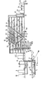
- the decanter is in the form of a prismatic tank surmounting a hopper and comprises a series of compartments, including oblique upper compartments contiguous to each other, the inlet being located in the first of these compartments where the water charged with particles circulates from top to bottom, while the current is upward in the other oblique compartments, a horizontal compartment opening under these oblique compartments and above a lower compartment forming the hopper intended for the evacuation of particles in the form of sludge.
- the installation shown in the drawing comprises a water intake apparatus, consisting of a partially submerged container 1, supported by streams teurs 2 (floating socket).
- the external shape of this container is suitable for its possible use in running water or running effluents, that is to say with a hydrodynamic front so as to allow an easy flow of water and aqueous effluents when they are in motion.
- the anchor point must be such that the tapered shape appears against the current.
- the rear consists of an inclined grid 3, preferably at 45 °, through which the water or the aqueous effluents to be treated enter the floating outlet.
- the layout of the grid at the rear and its inclination are intended to considerably reduce the accumulation of debris on it.
- the size of the meshes of the order of 2 mm, is chosen so that the most diverse objects (wood, leaves, possible animals) do not enter the device.
- the size of the meshes and the inclination of the grid also allow a partial unclogging of the grid by air injected behind the grid (acute angle side). This grid can be double, so that one can unclog one of the two without interrupting the operation of the entire installation.
- the part behind the grid consists of an aeration compartment 4 obtained by the release of compressed air in the form of fine bubbles, by means of porous tubes or plates for example.
- the flow rate of injected air is adaptable to the flow rate of the water or effluents to be treated, so that each liter thereof is aerated by a chosen quantity of air, preferably between 1 and 50 liters.
- the purpose of this air injection is to partially or completely remove volatile substances in solution or in dispersion in water (such as smelly and / or toxic products and / or light hydrocarbons, etc.). This also prevents entry into the device floating substances, such as oils, heavy hydrocarbons, etc.
- the ventilated part therefore begins under the grid and ends at a distance such that the air / water ratio or volume is preferably between 1 and 50.
- the compressed air release system is protected by a grid, which also has the function of better distributing the air bubbles.
- the degree of immersion of the device is such that the open edge of this compartment does not allow re-entry of water that has not passed through the grid 3.
- the edge emerges from about 5 cm to 10 cm above of the surface of the waters or aqueous effluents to be treated.
- the horizontality of the floating socket is adjusted by a mobile counterweight, preferably placed at the top, on the median axis in the direction of the length of the device. It can be constituted by a flashing lantern 5 fitted with its batteries or accumulators, serving as a nocturnal position indicator.
- the ventilation compartment 4 ends with a partition 6 whose height, from the bottom, is such that the air bubbles released cannot enter the last compartment where the submerged intake pump 7 is located.
- this system is in principle not limiting as to the number of solutions. It also allows effective contact between the water or aqueous effluents to be treated and the reagents.
- gaseous reactants such as, for example: chlorine, chlorine dioxide, sulfur dioxide, ozone, etc.
- these can, for example in this way, be introduced into the treatment circuit, under low pressure, when the latter is linked to its production system.
- this type of injection is limited when the flow rate of the gaseous reactant is too large, since there can be a defusing of the pump.
- This system is particularly advantageous for products which can undergo decomposition in metering pumps, such as hydrogen peroxide for example.
- this pump is fitted with a float switch which controls the operation and stopping of one or more pumps and metering pumps, valves, alarms, etc. inserted into the global processing circuit.
- Another characteristic of this pump is to be fixed on a frame itself detachable from the floating outlet.
- the delivery pipe of the pump To this frame are fixed the delivery pipe of the pump, the supply lines for liquid or gaseous reagents.
- the air supply to the ventilation system is fixed to the floating outlet.
- This frame can be placed in a container of cylindrical shape and of low height, screened at its upper part, so that water or aqueous effluents can penetrate through this opening to reach the pump without causing debris and especially of the vase or deposits.
- the intake pump (preferably of the self-priming type), can be placed on firm ground, provided that its suction duct (with or without foot valve) is located at the same place on the floating intake as was the water intake of the submerged pump from the first description.
- the water intake apparatus was immersed in the flow of water or aqueous effluents to be treated but, of course, it can also, according to the invention, be placed on the ground in a tank of a design similar to the floating outlet described above (grids, aeration compartment, pump), but the supply of water or aqueous effluents to said tank is made by means of either a pump submerged and a connecting pipe, either a pump placed on the ground and a connecting pipe, provided that its suction pipe (with strainer and with or without foot valve) submerges in water or the effluent.
- the installation also comprises a purification apparatus, which can be fixed or mobile and which consists of a control and junction panel 11 with the floating outlet 1, a treatment installation proper, and auxiliary apparatus.
- the control panel 11 comprises the various junctions by pipes and flexible wires between the floating outlet, the purification installation itself and the auxiliaries (compressors, generators of gaseous or solution reagents, electrical conductors). It also includes different control systems (adjustable valves, flowmeters, manometers, thermometers and analytical instruments).
- the treatment installation comprises a continuous reactor, a decanter and filters.
- the treatment of water and various aqueous effluents consists mainly of adding reagents in determined quantities depending on the nature and concentration of the pollutant (s), the volume to be treated and the time necessary for the chemical reactions to take place. , in order to obtain a water or an effluent that meets the purification criteria.
- a continuous tubular reactor 12 consisting of a pipe or tube, the dimensions of which are a function of the flow of water to be treated and the total time necessary to carry out all the chemical reactions d purification.
- reagent injection points supplied with dosing pumps with reagent tanks 13 to 17 at different lengths of this pipe.
- chemical and physical purification reactions require sometimes using solid and generally insoluble products, on the other hand, there is formation of precipitates, the design of such a treatment reactor requires a linear speed of the fluid (water or effluents + reactants in solution and / or in suspension + precipitates) such that there is no deposit inside the latter.
- a linear speed of the fluid is therefore imposed between 0.40 and 1 m / sec., Preferably from 0.55 to 0.70 m / sec.
- a treatment total depollution (before the separation of solids / purified liquid) must not last more than thirty to forty-five minutes, without this time being able to constitute a limitation. Obtained for these conditions, given by way of example, the theoretical limit lengths that the tubular reactor can have, ie 720 to 2,700 meters. As other factors must be taken into account, weight, size and cost in particular, it is considered that for these treatment times, the practical flow is of the order of 10 to 15 m3 / hour, especially if there is is transportable facilities.
- the most important problem is the provision of such a length in a compact form and taking into account the implementation of the material constituting the pipe.
- the tubular reactor is arranged in its total length or in sections thereof in one or more containers -, (understood in the broadest sense) preferably stackable.
- containers can be made in any mat-era, provided that the mechanical properties thereof allow.
- This container will preferably be in the form of a double parallelepiped or of a double cylinder or of any double intermediate shape, the concentric elements determining between them the container itself.
- the pipe is wound in contiguous or slightly spaced but parallel spirals from the inner edge of the large parallelepiped or large cylinder (inlet of the fluid opening onto the outer surface) towards the outer edge of the small parallelepiped or small cylinder, then by superposition on a lower spiral from the outer edge of the small parallelepiped or the small cylinder to the inner edge of the large parallelepiped or large cy lindre, so that the end of the reactor or a sec on of the latter can lead to an outer face, preferably on that of the inlet.
- the number of stages is therefore preferably chosen, so that the pipe or tube goes from the outside edge to the inside edge or vice versa.
- the container stacking system saves basic space compared to the system of placing containers side by side.
- the stacking system of the containers makes it possible in fact to obtain a continuous quasi-helical spiral going from the bottom to the top (if one places oneself from the point of view of the water or the effluents to be treated), so that gases or vapors can be more easily removed.
- Each container can contain one or more metering pumps in the free spaces and on the outside faces, there can be the inputs and outputs of reagents for metering pumps, indicator lights, inputs for probes or electrodes, or sensitive elements of instruments control lines which are inserted in the pipe, passages for supply conductors, so that each container can constitute a complete set of treatment.
- a static mixer can also be available after each reagent entry into the pipe.
- the section can also contain air-lifts and / or ejectors and / or ultrasonic generators.
- each container for reasons of weight, mechanical strength, ease of assembly, handling, transport or even to avoid crushing of the pipes if they are made of a flexible material (plastics for example) can only contain a limited number of superposed stages of pipes, especially if the spirals are arranged side by side without support, spacer or frame.
- the above does not exclude the use of these to ensure that this assembly has a certain immobilization of the pipe and also allow refrigeration or heating by fluid external to the pipe.
- another arrangement of the tubular reactor also consists in placing the pipe or tube in superposed concentric spirals, in the same design as that previously described and this in the widest sense, in a support frame, within which the pipe or tube constituting the tubular reactor can be fixed securely by means of fasteners or in notches cut from both vertical and horizontal supports.
- the support frame can contain the metering pumps and the external faces include the same elements as those arranged on the external faces of the containers previously described.
- the decanter has five compartments.
- the closed space above the water level allows the separation of gases, vapors or air from the water for the purpose of evacuation by a pipe 20.
- -Its lower part has inclined plates 21, preferably at 55 ° , on which the flocs brought by the water or the treated effluent slide. In this compartment, the water and the flocs go in the same direction, that is to say from top to bottom.
- the second compartment 22 is a free space in which the water and part of the precipitate flow horizontally.
- the third and fourth compartments 23, 24, placed side by side and also attached to the first, comprise tubes 25 or inclined plates, preferably at 55 °, in which the particles entrained by the rising current of water are deposited on those -this then descend in the opposite direction to the current towards the second compartment 22 and the fifth compartment 26
- the water speed is at least two times lower than that of the first compartment.
- an ascending speed of 1 mm / sec will be chosen.
- the fifth compartment 26 which is located under compartments one, three, qua-cre and two aims to concentrate by its pyramidal shape the particles from the other compartments.
- This fifth compartment is separated from the others by an assembly of vertical thin-walled tubes 27 2 cm to 5 cm in diameter, 10 cm long and joined to one another. These tubes can have an inclination of 0 ° to 60 °, angle formed by the direction of circulation of the water and the wall of the tubes (acute angle).
- a curved plate 22 ' partially covering these tubes 27, communicates a horizontal movement to the water.
- the purpose of the vertical, thin-walled tubes is, while letting the flocs descend into the fifth compartment, to create a zone without eddies, thus avoiding the upward entrainment of the already decanted flocs.
- a tube preferably connected to an adjustable flow pump 28 discharges the sludge formed by the flocs or the precipitate outside.
- one or more mechanical or electromagnetic vibrators can be arranged on the outer walls of the fifth compartment, although the anterior solution (vibrations within the suspension) is preferable, especially if it is a metallic decanter whose walls are welded.
- the level of this plate is preferably located a few centimeters below the level of the inlet tubing of the decanter.
- the water, freed for the most part from solid matter, is brought by gravity from the outlet of the decanter into a recovery tank 31, where the pump 32 is located or the intake of the pump supplying the filters 33.
- This tank is provided with a overflow and drain hose.
- the water level is controlled by two sensors, high level and low level, to which the operation of the pump supplying the filters is controlled.
- the useful volume of this tank is calculated in such a way that, taking into account the water outlet flow rate from the decanter, the pump does not switch on and off only a few times per hour of operation.
- the pipe joining the pump to the filters will be fitted with a non-return valve and a pressure gauge, preferably with contact, so as to indicate (lamp or acoustic signal) the set pressure limit of the filter (s) or the degree of clogging of this or these.
- the solid-liquid separation is refined by means of a filter or several filters arranged in parallel, the main characteristic of which is the filtering raw material (fabric, reinforced paper) is its porosity of 50 to 1 micron, preferably 10 to 5 microns.
- this filter 33 will be followed by bacteriological filters 34, the main characteristic of which is the porosity of 1 to 0.1 micron and preferably from 0.4 to 0 , 2 micron.
- the arrival of the reagents takes place at the top of the cone, and the exit of the reagents tangentially to the cylindrical part of the tank or the base of the cone.
- This arrangement of the tangential grip generates a vortex movement within the solution or suspension. Due to the arrival of solutions or suspensions in the center of the bottom of the tank, there is an energetic mixing of the solution or suspensions. In fact, especially in the case of suspensions, the particles launched by the current towards the surface of the solution or suspension tend to descend along the walls, where they again reach the central jet. They are therefore dragged back to the surface.
- the solution or suspension intake tubing intended for supplying the metering pumps is placed perpendicular to the wall of the cone of the tank, preferably between the top of the cone and the recovery tubing of the circulation pump.
Abstract
L'installation comporte deux éléments essentiels, d'une part, un appareillage de prise d'eau (1), dans lequel sont effectuées diverses opérations de traitement physiques et chemiques (3,8,9,10) et, d'autre part, un appareillage d'épuration plus élaboré comprenant un réacteur tubulaire (12) et un décanteur (18), asservi à l'appareillage de prise (1 ), spécialement en ce qui concerne le transfert des eaux à traiter, ce transfert depuis la prise jusqu'a la décantation étant réalisé au moyen d'une pompe unique (7), dont le débit contrôlé conditionne l'ensemble des traitements jusqu'a la décantation.
Description
Le prélèvement et le traitement classiques d'épuration d'eaux et d'effluents aqueux d'origines diverses comprennent généralement les étapes suivantes :
- 1°) Prélèvement ou prise de ces eaux et effluents aqueux au moyen d'une ou plusieurs pompes, avec élimination facultative des débris, grosses particules, objets, petits animaux, au moyen de grilles empêchant ceux-ci de pénétrer dans les pompes et les installations de traitement. Les grilles et les pompes (munies ou non de crépines), suivant les types d'installation, peuvent être situées sur plan ferme (à terre) ou portées par un ou plusieurs flotteurs.
- 2°) Un système d'élimination de substances, dont la densité est inférieure à celle des eaux et d'effluents aqueux, peut être ajouté en prétraitement pour éviter leur entraînement dans les installations de traitement ;
- 3°) Une filtration ou tamisage fin facultatif peut parfaire ce prétraitement des eaux et effluents aqueux avant les différentes étapes des traitements chimiques ou physiques proprement dits ;
- 4°) Les traitements chimiques de ces eaux sont conçus en fonction de la nature des pollutions, afin d'aboutir à une eau ou à des effluents aqueux satisfaisant à des normes légales ou à des concentrations non toxiques pour la faune et/ou la flore et/ou pour l'homme ou encore pour permettre certaines applications industrielles. Ces diverses opérations se font généralement dans une ou plusieurs cuves, dans le sens le plus large, placées généralement en série, dont la grandeur dépend principalement du débit à fournir, de la nature et de la durée des traitements appliqués.
- 5°) Une séparation des produits insolubles, résultant principalement des traitements chimiques, au moyen d'un ou plusieurs décanteurs et/ou de filtres (avec éventuellement un ou plusieurs concentrateurs de boues, lorsque l'importance ou la nature de l'installation les justifie) ;
- 6°) Si besoin est, un ou plusieurs traitements spécifiques, selon les buts poursuivis, comme par exemple, une stérilisation temporaire ou permanente jusqu'à utilisation ou réutilisation de ces eaux, ou encore l'addition de réactifs en vue d'apporter une modification de concentration d'une ou plusieurs substances minérales ou organiques de ces eaux ou ces effluents.
- 1 °) Sampling or taking of these waters and aqueous effluents by means of one or more pumps, with optional elimination of debris, large particles, objects, small animals, by means of grids preventing these from entering the pumps and treatment facilities. Grids and pumps (with or without strainers), depending on the type of installation, can be located on a firm surface (on the ground) or carried by one or more floats.
- 2) A system for removing substances, the density of which is lower than that of water and aqueous effluents, can be added as a pretreatment to avoid their entrainment in treatment facilities;
- 3 °) An optional fine filtration or sieving can perfect this pretreatment of water and aqueous effluents before the various stages of chemical or physical treatments proper;
- 4 °) The chemical treatments of these waters are designed according to the nature of the pollution, in order to result in water or aqueous effluents meeting legal standards or at non-toxic concentrations for fauna and / or flora. and / or for humans or to allow certain industrial applications. These various operations are generally carried out in one or more tanks, in the widest sense, generally placed in series, the size of which depends mainly on the flow rate to be supplied, the nature and the duration of the treatments applied.
- 5) separation of insoluble products, mainly resulting from chemical treatments, using one or more decanters and / or filters (with possibly one or more sludge concentrators, when the size or nature of the installation justifies);
- 6 °) If necessary, one or more specific treatments, depending on the goals pursued, such as, for example, temporary or permanent sterilization until use or reuse of these waters, or the addition of reagents in order to provide a change in the concentration of one or more mineral or organic substances in these waters or effluents.
Ces traitements classiques nécessitent généralement des surfaces étendues, un appareillage important, une infrastructure non négligeable, dont les coûts sont relativement élevés.These conventional treatments generally require large areas, a large apparatus, a significant infrastructure, the costs of which are relatively high.
Si dans le cas de besoins importants, publics ou industriels, les coûts sont justifiés,il n'en est pas de même dans le cas des faibles débits (inférieurs par exemple à 50 m3/heure), spécialement lorsque ceux-ci sont limités dans le temps ou occasionnels, et que ces installations sont à poste fixe ou mobiles.If in the case of large public or industrial needs, the costs are justified, it is not the same in the case of low flows (lower than for example 50 m3 / hour), especially when these are limited in time or occasional, and that these installations are fixed or mobile.
D'autre part, la conception générale de grandes installations peut difficilement être extrapolée à de petites installations, lorsque celles-ci doivent être compactes et légères et que les durées de chaque étape complète du ou des traitements sont limitées pour ces raisons dans le temps.On the other hand, the general design of large installations can hardly be extrapolated to small installations, when these must be compact and light and the durations of each complete stage of the treatment or treatments are limited for these reasons over time.
Ceci vaut spécialement pour les installations mobiles, car dans ce cas, il faut assurer, pour obtenir un rendement optimal, des étapes de traitements complets mais de durées bien définies, ces facteurs influençant la grandeur et/ou le poids de l'installation à transporter, avec pour conséquence notamment une répercussion sur le coût de l'installation et du traitement global.This is especially true for mobile installations, because in this case it is necessary to ensure, in order to obtain optimal yield, complete treatment steps but well defined durations, these factors influencing the size and / or the weight of the installation to be transported, with the consequence in particular of an impact on the cost of installation and overall treatment.
La présente invention est relative à une installation compacte et simplifiée de prélèvement et de traitements divers d'épuration d'eaux et d'effluents aqueux d'origines diverses, de préférence mobile, sans que cette dernière caractéristique soit limitative. Le terme mobile doit être interprété également comme transportable.The present invention relates to a compact and simplified installation for sampling and various treatments for the purification of water and aqueous effluents of various origins, preferably mobile, without this latter characteristic being limiting. The term mobile should also be interpreted as transportable.
La compacité et la simplification de l'installation visent également l'allègement en poids de l'ensemble, quand ce dernier facteur est important pour le moyen de transport envisagé (avion, bateau, véhicule terrestre).The compactness and simplification of the installation also aim to reduce the weight of the whole, when this last factor is important for the means of transport envisaged (plane, boat, land vehicle).
L'installation faisant l'objet de la présente invention est caractérisée par le fait qu'elle comporte deux éléments essentiels, d'une part un appareillage de prise d'eau, dans lequel sont effectuées diverses opérations de traitements physiques et chimiques et, d'autre part, un appareillage d'épuration plus élaboré asservi à l'appareillage de prise, spécialement en ce qui concerne le transfert des eaux ou des effluents aqueux à traiter, ce transfert depuis la prise jusqu'à la décantation étant réalisé au moyen d'une pompe unique, dont le débit contrôlé conditionne l'ensemble des traitements jusqu'à la décantation.The installation which is the subject of the present invention is characterized in that it comprises two essential elements, on the one hand a water intake apparatus, in which various physical and chemical treatment operations are carried out and, d 'on the other hand, a more elaborate purification apparatus subject to the intake apparatus, especially with regard to the transfer of the waters or aqueous effluents to be treated, this transfer from the intake to the settling being carried out by means of '' a single pump, whose controlled flow conditions all of the treatments until decantation.
Suivant l'invention, l'appareillage de prise d'eau comporte un compartiment d'aération obtenue par dégagement d'air comprimé sous forme de fines bulles, le débit d'air injecté étant adaptable au débit des eaux ou des effluents à traiter.According to the invention, the water intake apparatus comprises an aeration compartment obtained by the release of compressed air in the form of fine bubbles, the flow rate of injected air being adaptable to the flow rate of the water or effluents to be treated.
Egalement suivant l'invention, la pompe de prise est agencée de telle manière qu'elle aspire, à travers l'appareillage de prise, l'eau et les effluents aqueux en permettant leur aération, refoule l'eau et les effluents aqueux vers l'appareillage d'épuration élaborée, et permet d'effectuer un prétraitement chimique par réactifs gazeux ou liquides par injection de réactifs aux entrées d'eaux ou d'effluents aqueux dans ladite pompe.Also according to the invention, the pump intake is arranged in such a way that it draws water and aqueous effluents through the intake apparatus, allowing their aeration, discharges the water and aqueous effluents towards the elaborate purification apparatus, and allows to carry out a chemical pretreatment with gaseous or liquid reagents by injection of reagents at the entry of water or aqueous effluents into said pump.
L'installation de traitement proprement dite conforme à l'invention comporte dans l'ordre un réacteur tubulaire continu, un décanteur du type à décantation accélérée, et un ou plusieurs filtres.The actual treatment installation according to the invention comprises, in order, a continuous tubular reactor, a settling tank of the accelerated settling type, and one or more filters.
Suivant l'invention, le réacteur tubulaire continu est constitué par un tuyau ou tube disposé en spirales concentriques superposées.According to the invention, the continuous tubular reactor consists of a pipe or tube arranged in superposed concentric spirals.
Suivant l'invention encore, le décanteur se présente sous la forme d'un réservoir prismatique surmontant une trémie et comporte une série de compartiments, dont des compartiments supérieurs obliques accolés l'un à l'autre, l'entrée étant située dans le premier de ces compartiments où l'eau chargée de particules circule de haut en bas, tandis que le courant est ascensionnel dans les autres compartiments obliques, un compartiment horizontal s'ouvrant sous ces compartiments obliques et au-dessus d'un compartiment inférieur formant la trémie destiné à l'évacuation des particules sous forme de boues.According to the invention also, the decanter is in the form of a prismatic tank surmounting a hopper and comprises a series of compartments, including oblique upper compartments contiguous to each other, the inlet being located in the first of these compartments where the water charged with particles circulates from top to bottom, while the current is upward in the other oblique compartments, a horizontal compartment opening under these oblique compartments and above a lower compartment forming the hopper intended for the evacuation of particles in the form of sludge.
Pour mieux faire comprendre l'invention, celle-ci est décrite maintenant, avec plus de détails, sur la base du dessin schématique annexé d'un exemple de réalisation d'une installation de prélèvement et de traitement d'épuration d'eaux et d'effluents aqueux.To better understand the invention, it is now described, in more detail, on the basis of the appended schematic drawing of an exemplary embodiment of an installation for sampling and treatment of water purification and d 'aqueous effluents.
L'installation représentée au dessin comporte un appareillage de prise d'eau, constitué par un récipient 1 partiellement immergé, supporté par des flotteurs 2 (prise flottante). La forme extérieure de ce récipient est adaptée à son utilisation possible en eau courante ou effluents courants, c'est-à-dire avec un avant hydrodynamique de manière à permettre un écoulement aisé des eaux et des effluents aqueux lorsque ceux-ci sont en mouvement. Le point d'ancrage doit être tel que la forme effilée se présente à contre-courant. L'arrière est constitué par une grille inclinée 3, de préférence à 45°, par où les eaux ou les effluents aqueux à traiter entrent dans la prise flottante.The installation shown in the drawing comprises a water intake apparatus, consisting of a partially submerged container 1, supported by streams teurs 2 (floating socket). The external shape of this container is suitable for its possible use in running water or running effluents, that is to say with a hydrodynamic front so as to allow an easy flow of water and aqueous effluents when they are in motion. . The anchor point must be such that the tapered shape appears against the current. The rear consists of an
La disposition de la grille à l'arrière et son inclinaison ont pour but de diminuer considérablement l'accumulation de débris sur celle-ci. La grandeur des mailles, de l'ordre de 2 mm, est choisie de telle sorte que les objets les plus divers (bois, feuilles, animaux éventuels) ne pénètrent dans l'appareil. La grandeur des mailles et l'inclinaison de la grille permettent également un décolmatage partiel de la grille par de l'air injecté derrière la grille (côté angle aigu). Cette grille peut être double, de telle sorte que l'on puisse en décolmater l'une des deux sans interrompre le fonctionnement de l'ensemble de l'installation.The layout of the grid at the rear and its inclination are intended to considerably reduce the accumulation of debris on it. The size of the meshes, of the order of 2 mm, is chosen so that the most diverse objects (wood, leaves, possible animals) do not enter the device. The size of the meshes and the inclination of the grid also allow a partial unclogging of the grid by air injected behind the grid (acute angle side). This grid can be double, so that one can unclog one of the two without interrupting the operation of the entire installation.
La partie située derrière la grille est constituée par un compartiment d'aération 4 obtenue par dégagement d'air comprimé sous forme de fines bulles, au moyen de tubes ou plaques poreuses par exemple. Le débit d'air injecté est adaptable au débit des eaux ou des effluents à traiter, de telle sorte que chaque litre de ceux-ci soit aéré par une quantité d'air choisie, de préférence entre 1 et 50 litres. Cette injection d'air a pour but d'éliminer partiellement ou totalement par déplacement les substances volatiles en solution ou en dispersion dans l'eau (tels que produits malodorants et/ ou toxiques et/ou des hydrocarbures légers, etc.). Cette opération évite également l'introduction dans l'appareil des substances flottantes, tels que huiles, hydrocarbures lourds, etc. La partie aérée commence donc sous la grille et se termine à une distance telle que le rapport ou volume air/eau soit de préférence entre 1 et 50.The part behind the grid consists of an aeration compartment 4 obtained by the release of compressed air in the form of fine bubbles, by means of porous tubes or plates for example. The flow rate of injected air is adaptable to the flow rate of the water or effluents to be treated, so that each liter thereof is aerated by a chosen quantity of air, preferably between 1 and 50 liters. The purpose of this air injection is to partially or completely remove volatile substances in solution or in dispersion in water (such as smelly and / or toxic products and / or light hydrocarbons, etc.). This also prevents entry into the device floating substances, such as oils, heavy hydrocarbons, etc. The ventilated part therefore begins under the grid and ends at a distance such that the air / water ratio or volume is preferably between 1 and 50.
Le système de dégagement d'air comprimé est protégé par une grille, qui a pour fonction également de mieux répartir les bulles d'air.The compressed air release system is protected by a grid, which also has the function of better distributing the air bubbles.
Le degré d'immersion de l'appareil est tel que le bord ouvert de ce compartiment ne permet pas de rentrée d'eau n'ayant pas passé par la grille 3. Le bord émerge d'environ 5 cm à 10 cm au-dessus de la surface des eaux ou des effluents aqueux à traiter.The degree of immersion of the device is such that the open edge of this compartment does not allow re-entry of water that has not passed through the
Le réglage de l'horizontalité de la prise flottante s'effectue par un contre-poids mobile, placé de préférence à la partie supérieure, sur l'axe médian dans le sens de la longueur de l'appareil. Il peut être constitué par un fanal clignotant 5 muni de ses piles ou accus, servant d'indicateur nocturne de position.The horizontality of the floating socket is adjusted by a mobile counterweight, preferably placed at the top, on the median axis in the direction of the length of the device. It can be constituted by a flashing lantern 5 fitted with its batteries or accumulators, serving as a nocturnal position indicator.
Le compartiment d'aération 4 se termine par une cloison 6 dont la hauteur, à partir du fond, est telle que les bulles d'air dégagées ne puissent entrer dans le dernier compartiment où se trouve la pompe de prise immergée 7.The ventilation compartment 4 ends with a
Cette pompe a plusieurs fonctions :
- a. Elle aspire l'eau ou les effluents aqueux de l'arrière de la prise flottante vers l'avant de celle-ci en assurant son tamisage au travers des grilles situées à l'arrière ;
- b. Elle permet l'aération des eaux ou des effluents aqueux par le transfert de ceux-ci de l'arrière vers l'avant ;
- c. Elle refoule l'eau ou les effluents aqueux vers l'appareillage d'épuration élaborée, situé généralement à terre ;
- d. Elle permet en outre d'effectuer un prétraitement chimique par réactifs gazeux ou liquides, en insérant aux entrées d'eaux ou d'effluents aqueux dans la pompe proprement dite, une ou plusieurs tubulures d'arrivées de réactifs.
- at. It sucks up water or aqueous effluents from the rear of the floating intake towards the front thereof, ensuring its sieving through the grids located at the rear;
- b. It allows the aeration of water or aqueous effluents by the transfer of these from the rear to the front;
- vs. It delivers water or aqueous effluents to the elaborate purification equipment, generally located on land;
- d. It also allows you to make a pre chemical treatment with gaseous or liquid reagents, by inserting at the entry of water or aqueous effluents into the pump proper, one or more tubes of reagent arrivals.
En ce qui concerne l'injection de réactifs en solution (9), ce système n'est en principe pas limitatif quant au nombre de solutions. Il permet en outre un contact efficace entre l'eau ou les effluents aqueux à traiter et les réactifs.With regard to the injection of reagents in solution (9), this system is in principle not limiting as to the number of solutions. It also allows effective contact between the water or aqueous effluents to be treated and the reagents.
En ce qui concerne l'injection des réactifs gazeux (8, 10) tels que, par exemple : du chlore, du dioxyde de chlore, de l'anhydride sulfureux, de l'ozone, etc., ceux-ci peuvent, par exemple de cette manière, être introduits dans le circuit de traitement, sous faible pression, lorsque cette dernière est liée à son système de production.As regards the injection of gaseous reactants (8, 10) such as, for example: chlorine, chlorine dioxide, sulfur dioxide, ozone, etc., these can, for example in this way, be introduced into the treatment circuit, under low pressure, when the latter is linked to its production system.
Pour certains types de pompes, on est toutefois limité quant à ce type d'injection quand le débit du réactif gazeux est trop grand, car il peut se produire un désamorçage de la pompe. Ce système est particulièrement intéressant pour les produits pouvant subir une décomposition dans les pompes doseuses, comme de l'eau oxygénée par exemple.For certain types of pumps, however, this type of injection is limited when the flow rate of the gaseous reactant is too large, since there can be a defusing of the pump. This system is particularly advantageous for products which can undergo decomposition in metering pumps, such as hydrogen peroxide for example.
Une des caractéristiques de cette pompe est d'être munie d'un interrupteur à flotteur qui commande le fonctionnement et l'arrêt d'une ou de plusieurs pompes et pompes doseuses, vannes, alarmes, etc. insérées dans le circuit global du traitement. Une autre caractéristique de cette pompe est d'être fixée sur un bâti lui-même détachable de la prise flottante.One of the characteristics of this pump is that it is fitted with a float switch which controls the operation and stopping of one or more pumps and metering pumps, valves, alarms, etc. inserted into the global processing circuit. Another characteristic of this pump is to be fixed on a frame itself detachable from the floating outlet.
A ce bâti sont fixés le tuyau de refoulement de la pompe, les conduits d'amenée des réactifs liquides ou gazeux. L'arrivée d'air alimentant le système d'aération est fixéeà la prise flottante.To this frame are fixed the delivery pipe of the pump, the supply lines for liquid or gaseous reagents. The air supply to the ventilation system is fixed to the floating outlet.
Le bâti auquel sont fixés la pompe et les conduits d'amenée des réactifs gazeux et/ou liquides est- détachable de la prise flottante pour pouvoir être utilisé pour des prises d'eau ou d'effluents aqueux dans les cas où la profondeur n'est pas suffisante pour permettre l'utilisation de la prise flottante (cas des torrents ou des caniveaux par exemple).The frame to which the pump and the supply lines for gaseous and / or liquid reagents is detachable from the floating outlet so that it can be used for water or aqueous effluent outlets in cases where the depth is not sufficient to allow the use of the floating outlet (torrents or gutters for example).
Ce bâti peut se placer dans un récipient de forme cylindrique et de faible hauteur, grillagé à sa partie supérieure, de telle sorte que l'eau ou les effluents aqueux puissent pénétrer par cette ouverture pour atteindre la pompe sans entraîner de débris et surtout de la vase ou des dépôts.This frame can be placed in a container of cylindrical shape and of low height, screened at its upper part, so that water or aqueous effluents can penetrate through this opening to reach the pump without causing debris and especially of the vase or deposits.
Il va de soi que dans le cadre du système proposé, la pompe de prise (de préférence du type auto- amorçante), peut être placée sur terrain ferme, pour autant que son conduit d'aspiration (avec ou sans clapet de pied) soit situé au même endroit sur la prise flottante que l'était la prise d'eau de la pompe immergée de la première description.It goes without saying that under the proposed system, the intake pump (preferably of the self-priming type), can be placed on firm ground, provided that its suction duct (with or without foot valve) is located at the same place on the floating intake as was the water intake of the submerged pump from the first description.
Il va de soi également, que dans ces conditions, les conduits d'arrivée des réactifs gazeux ou liquides sont proches ou situés à l'intérieur de ce tuyau d'aspiration d'eau. Il est aussi évident que l'interrupteur à flotteur, commandant la pompe et d'autres systèmes asservis, se trouve également dans la prise flottante. Il va de soi que la nature des matériaux utilisés est telle qu'ils résistent aux actions des eaux à traiter et des réactifs employés. En ce qui concerne les liaisons hydrauliques et électriques, elles sont effectuées par des raccords étanches, de préférence du type rapide.It also goes without saying that, under these conditions, the inlet conduits for the gaseous or liquid reactants are close to or located inside this water suction pipe. It is also obvious that the float switch, controlling the pump and other slave systems, is also in the floating outlet. It goes without saying that the nature of the materials used is such that they resist the actions of the water to be treated and the reagents used. As regards the hydraulic and electrical connections, they are carried out by watertight connections, preferably of the rapid type.
On a supposé dans la description qui précède que l'appareillage de prise d'eau était immergé dans le courant des eaux ou des effluents aqueux à traiter mais, bien entendu, il peut aussi suivant l'invention être disposé sur le terrain dans un réservoir de conception analogue à la prise flottante précédemment décrite (grilles, compartiment d'aération, pompe), mais l'alimentation en eaux ou effluents aqueux dudit réservoir est faite par l'intermédiaire, soit d'une pompe immergée et d'un tuyau de raccordement, soit d'une pompe placée à terre et d'un tuyau de raccordement, pour autant que son conduit d'aspiration (avec crépine et avec ou sans clapet de pied) plonge dans l'eau ou l'effluent.It has been assumed in the foregoing description that the water intake apparatus was immersed in the flow of water or aqueous effluents to be treated but, of course, it can also, according to the invention, be placed on the ground in a tank of a design similar to the floating outlet described above (grids, aeration compartment, pump), but the supply of water or aqueous effluents to said tank is made by means of either a pump submerged and a connecting pipe, either a pump placed on the ground and a connecting pipe, provided that its suction pipe (with strainer and with or without foot valve) submerges in water or the effluent.
L'installation comporte d'autre part un appareillage d'épuration, qui peut être fixe ou mobile et qui consiste en un tableau de commande et de jonction 11 avec la prise flottante 1, une installation de traitement proprement dite, et des appareillages auxiliaires.The installation also comprises a purification apparatus, which can be fixed or mobile and which consists of a control and
Le tableau de commande 11 comporte les jonctions diverses par tuyaux et fils souples entre la prise flottante, l'installation d'épuration proprement dite et les auxiliaires (compresseurs, générateurs de réactifs gazeux ou en solution, conducteurs électriques). Il comporte également différents systèmes de contrôle (vannes réglables, débitmètres, manomètres, thermomètres et des instruments analytiques).The
De son côté, l'installation de traitement comporte un réacteur continu, un décanteur et des filtres.For its part, the treatment installation comprises a continuous reactor, a decanter and filters.
Le traitement des eaux et des effluents aqueux divers consiste principalement à ajouter des réactifs dans des quantités déterminées en fonction de la nature et de la concentration du ou des polluants, du volume à traiter et du temps nécessaire pour que les réactions chimiques puissent s'effectuer, afin d'obtenir une eau ou un effluent répondant aux critères d'épuration.The treatment of water and various aqueous effluents consists mainly of adding reagents in determined quantities depending on the nature and concentration of the pollutant (s), the volume to be treated and the time necessary for the chemical reactions to take place. , in order to obtain a water or an effluent that meets the purification criteria.
Etant donné que dans certains cas, le volume et/ou le poids de l'installation sont des paramètres importants, il y a lieu d'effectuer chaque réaction d'épuration dans le temps le plus court, ce qui implique une parfaite homogénéisation du mélange eau à traiter et réactifs, spécialement si ces derniers sont faiblement solubles ou insolubles (cas d'introduction d'adsorbants ou de résines échangeuses d'ions organiques et inorganiques). Il est, d'autre part, intéressant d'utiliser complètement des réactifs gazeux (chlore, anhydride car- conique, anhydride sulfureux, bioxyde de chlore, ozone, etc.).Since in certain cases the volume and / or the weight of the installation are important parameters, it is necessary to carry out each purification reaction in the shortest time, which implies a perfect homogenization of the water mixture to be treated and reagents, especially if the latter are poorly soluble or insoluble (case of introduction of adsorbents or organic and inorganic ion exchange resins). On the other hand, it is advantageous to use gaseous reagents completely (chlorine, carbon dioxide, sulfur dioxide, chlorine dioxide, ozone, etc.).
Or, on constate bien souvent dans la pratique, une perte partielle de ceux-ci avec pour conséquence un risque de pollution gazeuse et un danger pour le personnel travaillant autour de l'installation. Ce cas se présente généralement dans des cuves de traitement placées en série dans une installation classique d'épuration.However, it is very often observed in practice, a partial loss of these with the consequence of a risk of gaseous pollution and a danger for the personnel working around the installation. This case generally occurs in treatment tanks placed in series in a conventional purification installation.
C'est pourquoi il a été préféré, suivant l'invention, un réacteur tubulaire continu 12 constitué par un tuyau ou tube, dont les dimensions sont fonction du débit d'eau à traiter et du temps total nécessaire pour effectuer toutes les réactions chimiques d'épuration. Comme chaque réaction doit s'effectuer dans un temps donné, on dispose à différentes longueurs de ce tuyau des points d'injection de réactifs alimentés par des pompes doseuses avec cuves à réactifs 13 à 17. Comme les réactions chimiques et physiques d'épuration mettent parfois en oeuvre des produits solides et généralement insolubles, que d'autre part, il y a formation de précipités, la conception d'un tel réacteur de traitement impose une vitesse linéaire du fluide (eau ou effluents + réactifs en solution et/ou en suspension + précipités) telle qu'il n'y ait pas de dépôt à l'intérieur de ce dernier. On impose donc une vitesse linéaire du fluide comprise entre 0,40 et 1 m/sec., de préférence de-0,55 à 0,70 m/ sec.This is why it has been preferred, according to the invention, a continuous
D'autre part, on considère qu'un traitement total de dépollution (avant la séparation des matières solides/liquide épuré) ne doit pas durer plus de trente à quarante-cinq minutes, sans que ce temps puisse constituer une limitation. On obtient pour ces conditions, données à titre exemplatif, les longueurs limites théoriques que peut avoir le réacteur tubulaire, soit donc 720 à 2.700 mètres. Comme d'autres facteurs doivent entrer en ligne de compte, poids, encombrement et coût notamment, on considère que pour ces durées de traitement, le débit pratique est de l'ordre de 10 à 15 m3/heure, spécialement s'il s'agit d'installations transportables.On the other hand, it is considered that a treatment total depollution (before the separation of solids / purified liquid) must not last more than thirty to forty-five minutes, without this time being able to constitute a limitation. Obtained for these conditions, given by way of example, the theoretical limit lengths that the tubular reactor can have, ie 720 to 2,700 meters. As other factors must be taken into account, weight, size and cost in particular, it is considered that for these treatment times, the practical flow is of the order of 10 to 15 m3 / hour, especially if there is is transportable facilities.
Dès lors, le problème le plus important est la disposition d'une telle longueur sous une forme compacte et tenant compte de la mise en oeuvre de la matière constituant le tuyau.Therefore, the most important problem is the provision of such a length in a compact form and taking into account the implementation of the material constituting the pipe.
Suivant la présente invention, le réacteur tubulaire est disposé dans sa longueur totale ou en sections de celle-ci dans un ou plusieurs conteneurs-,(compris dans le sens le plus large) de préférence superposables. Ces conteneurs peuvent être réalisés en toute mat-ère, pour autant que les propriétés mécaniques de celles-ci le permettent. Ce conteneur se présentera, de préférence, sous la forme d'un double parallélépipède ou d'un double cylindre ou de toute forme double intermédiaire, les éléments concentriques déterminant entre eux le conteneur proprement dit.According to the present invention, the tubular reactor is arranged in its total length or in sections thereof in one or more containers -, (understood in the broadest sense) preferably stackable. These containers can be made in any mat-era, provided that the mechanical properties thereof allow. This container will preferably be in the form of a double parallelepiped or of a double cylinder or of any double intermediate shape, the concentric elements determining between them the container itself.
A l'intérieur de ce conteneur, le tuyau est enroulé en spirales jointives ou légèrement espacées mais parallèles à partir du bord intérieur du grand parallélépipède ou grand cylindre (entrée du fluide débouchant sur la surface extérieure) vers le bord extérieur du petit parallélépipède ou petit cylindre, puis par superposition sur une spirale inférieure du bord extérieur du petit parallélépipède ou du petit cylindre vers le bord intérieur du grand parallélépipède ou du grand cylindre, de telle sorte que la fin du réacteur ou d'une sec on de ce dernier puisse aboutir sur une face extérieure, de préférence sur celle de l'entrée.Inside this container, the pipe is wound in contiguous or slightly spaced but parallel spirals from the inner edge of the large parallelepiped or large cylinder (inlet of the fluid opening onto the outer surface) towards the outer edge of the small parallelepiped or small cylinder, then by superposition on a lower spiral from the outer edge of the small parallelepiped or the small cylinder to the inner edge of the large parallelepiped or large cy lindre, so that the end of the reactor or a sec on of the latter can lead to an outer face, preferably on that of the inlet.
Le nombre d'étages est donc choisi de préférence, pour que le tuyau ou tube aille du bord extérieur vers le bord intérieur ou vice versa.The number of stages is therefore preferably chosen, so that the pipe or tube goes from the outside edge to the inside edge or vice versa.
Il va de soi que les propriétés mécaniques du conteneur seront un des facteurs limitatifs de ses dimensions.It goes without saying that the mechanical properties of the container will be one of the limiting factors of its dimensions.
Comme la courbure du tuyau ou tube doit être limitée pour diverses raisons, principalement mécaniques, il existe une zone inutilisée dans la partie centrale du conteneur et dans les quatre coins de ce dernier, si une forme parallélépipédique stricte est appliquée. Ceci n'exclut pas, dans la même idée, un conteneur en forme de couronne, avec ou sans parties droites.As the curvature of the pipe or tube must be limited for various reasons, mainly mechanical, there is an unused area in the central part of the container and in the four corners of the latter, if a strict parallelepiped shape is applied. This does not exclude, in the same idea, a container in the shape of a crown, with or without straight parts.
Les avantantages de la disposition du tube ou tuyau dans un conteneur sont les suivants :
- a. Contenir la spirale continue (forme hélicoïdale) ;
- b. Permettre éventuellement un chauffage ou un refroidissement du tuyau au moyen d'un fluide extérieur ;
- c. Obtenir un système souple pour effectuer les traitements divers, en ce sens que si l'on désire augmenter ou diminuer, par exemple, les temps de réaction, on peut ajouter ou retrancher un ou plusieurs conteneurs, ceux-ci étant interconnectables.
- at. Contain the continuous spiral (helical shape);
- b. Possibly allow heating or cooling of the pipe by means of an external fluid;
- vs. Obtain a flexible system for carrying out the various treatments, in the sense that if one wishes to increase or decrease, for example, the reaction times, one or more containers can be added or subtracted, these being interconnectable.
Le système d'empilement des conteneurs permet une économie de surface de base par rapport au système de disposition des conteneurs les uns à côté des autres.The container stacking system saves basic space compared to the system of placing containers side by side.
Il permet, en outre, toujours dans un souci d'économie de place, d'utiliser la partie centrale pour y placer un décanteur 18, de préférence du type à décantation accélérée (à tubes, à plaques, etc.), la sortie du tuyau de conteneur supérieur pouvant correspondre à l'entrée dudit décanteur.It also allows, still for the sake of saving space, to use the central part to place a
Le système d'empilement des conteneurs permet d'obtenir en fait une spirale continue quasi hélicoïdale allant du bas vers le haut (si l'on se place du point de vue de l'eau ou des effluents à traiter), de telle sorte que des gaz ou vapeurs peuvent être plus facilement éliminés.The stacking system of the containers makes it possible in fact to obtain a continuous quasi-helical spiral going from the bottom to the top (if one places oneself from the point of view of the water or the effluents to be treated), so that gases or vapors can be more easily removed.
De toute façon, aux vitesses de l'eau ou des effluents préconisées ici il n'y a pas d'accumulation de gaz ou vapeurs, même si, par exemple, dans la section réservée à la floculation, le liquide circule éventuellement de haut en bas, afin d'entraîner plus facilement les flocs, parfois lourds et susceptibles de circuler à vitesse moins élevée que le liquide (risque d'accumulation).In any case, at the speeds of water or effluents recommended here there is no accumulation of gases or vapors, even if, for example, in the section reserved for flocculation, the liquid possibly circulates from top to low, in order to more easily carry the flocs, which are sometimes heavy and likely to circulate at a lower speed than the liquid (risk of accumulation).
Chaque conteneur peut contenir dans les espaces libres une ou plusieurs pompes doseuses et sur les faces extérieures, on peut disposer les entrées et sorties de réactifs pour pompes doseuses, les voyants de passage, des entrées pour sondes ou électrodes, ou éléments sensibles d'instruments de contrôle qui sont insérés dans le tuyau, des passages pour conducteurs d'alimentation, de manière que chaque conteneur puisse constituer un ensemble complet de traitement.Each container can contain one or more metering pumps in the free spaces and on the outside faces, there can be the inputs and outputs of reagents for metering pumps, indicator lights, inputs for probes or electrodes, or sensitive elements of instruments control lines which are inserted in the pipe, passages for supply conductors, so that each container can constitute a complete set of treatment.
Si besoin est, on peut disposer, également après chaque entrée de réactif dans le tuyau, un mélangeur statique. La section peut contenir également des air-lifts et/ou des éjecteurs et/ou des générateurs d'ultrasons.If necessary, a static mixer can also be available after each reagent entry into the pipe. The section can also contain air-lifts and / or ejectors and / or ultrasonic generators.
Il va de soi que ces conteneurs, lorsqu'ils sont superposés peuvent être fixés les uns aux autres, soit par des attaches, dans le sens le plus large, y compris des pattes situées sur la face intérieure s'em- boitant dans des alvéoles prévues à cet effet dans le conteneur qui lui est inférieur.It goes without saying that these containers, when superimposed can be fixed to one another, either by fasteners, in the widest sense, including tabs located on the inner face which are interlocked in cells provided for this purpose in the container below it.
Pour des raisons d'économie, on peut également rendre étanche la jonction entre deux conteneurs superposables, de telle façon que le fond de l'un corresponde au couvercle de l'autre.For reasons of economy, it is also possible to seal the junction between two stackable containers, so that the bottom of one corresponds to the cover of the other.
Comme il a été dit plus avant, chaque conteneur, pour des raisons de poids, de résistance mécanique, de facilité de montage, de manutention, de transport ou encore pour éviter l'écrasement des tuyaux si ceux-ci sont constitués par une matière souple (matières plastiques par exemple) ne peut contenir qu'un nombre limité d'étages superposés de tuyaux, spécialement si les spirales sont disposées côte à côte sans support ni pièce d'écartement, ni armature. Toutefois, ce qui précède n'exclut pas l'utilisation de ceux-ci pour assurer à cet assemblage une certaine immobilisation du tuyau et également permettre une réfrigération ou un chauffage par fluide extérieur au tuyau.As was said above, each container, for reasons of weight, mechanical strength, ease of assembly, handling, transport or even to avoid crushing of the pipes if they are made of a flexible material (plastics for example) can only contain a limited number of superposed stages of pipes, especially if the spirals are arranged side by side without support, spacer or frame. However, the above does not exclude the use of these to ensure that this assembly has a certain immobilization of the pipe and also allow refrigeration or heating by fluid external to the pipe.
Pour autant que le poids et l'encombrement le permettent, une autre disposition du réacteur tubulaire consiste également à placer le tuyau ou tube en spirales concentriques superposées, dans la même conception que celle précédemment décrite et ceci dans le sens le plus large, dans une armature support, au sein de laquelle le tuyau ou tube constituant le réacteur tubulaire peut être fixé solidement au moyen d'attaches ou dans des encoches découpées dans des supports tant verticaux qu'horizontaux.As far as the weight and size allow, another arrangement of the tubular reactor also consists in placing the pipe or tube in superposed concentric spirals, in the same design as that previously described and this in the widest sense, in a support frame, within which the pipe or tube constituting the tubular reactor can be fixed securely by means of fasteners or in notches cut from both vertical and horizontal supports.
Il va de soi que ce type de conception, comme le précédent, doit permettre le jeu normal de dilatation et d'allongement du tuyau.It goes without saying that this type of design, like the previous one, must allow the normal play of expansion and elongation of the pipe.
Comme dans le cas précédent, l'armature-support peut contenir les pompes doseuses et les faces extérieures comprennent les mêmes éléments que ceux disposés sur les faces extérieures des conteneurs précédemment décrits.As in the previous case, the support frame can contain the metering pumps and the external faces include the same elements as those arranged on the external faces of the containers previously described.
Le décanteur 18 prévu pour cette installation est de préférence du type à décantation accélérée, à tubes ou à plaques, auquel il est apporté différents perfectionnements. Il se présente sous la forme d'un prisme oblique à base rectangulaire accolé par la base à une pyramide inversée. Ses fonctions sont les suivantes :
- a) Assurer l'évacuation des gaz, vapeurs ou air sans pollution de l'environnement immédiat de l'installation ;
- b) Séparer les flocs de l'eau ou des effluents traités ;
- c) Entraîner la majeure partie des flocs ou précipité à l'extérieur de l'installation.
- a) Ensure the evacuation of gases, vapors or air without pollution of the immediate environment of the installation;
- b) Separate the flocs from the treated water or effluents;
- c) entraining most of the flocs or precipitated outside the installation.
Le décanteur comporte cinq compartiments. Le premier 19, où se situe à la partie supérieure l'entrée du décanteur, reçoit les gaz, vapeurs, l'air et l'eau chargée de particules en suspension (flocs). L'espace fermé surmontant le niveau d'eau permet la séparation des gaz, vapeurs ou d'air de l'eau aux fins d'évacuation par une tuyauterie 20. -Sa partie inférieure comporte des plaques inclinées 21, de préférence à 55°, sur lesquelles glissent les flocs apportés par l'eau ou les effluents traités. Dans ce compartiment, l'eau et les flocs vont dans le même sens, c'est-à-dire du haut vers le bas.The decanter has five compartments. The first 19, where the entrance to the decanter is located at the top, receives the gases, vapors, air and water laden with particles in suspension (flocs). The closed space above the water level allows the separation of gases, vapors or air from the water for the purpose of evacuation by a
Le deuxième compartiment 22 est un espace libre dans lequel l'eau et une partie du précipité circulent horizontalement.The
Les troisième et quatrième compartiments 23, 24, placés côte à côte et également accolés au premier, comportent des tubes 25 ou plaques inclinées, de préférence à 55°, dans lesquels les particules entraînées par le courant ascensionnel de l'eau se déposent sur ceux-ci puis descendent en sens inverse au courant vers le deuxième compartiment 22 et le cinquième comcartiment 26The third and
Dans ces compartiments, la vitesse de l'eau est au minimum de deux fois inférieure à celle du premier compartiment. On choisira, de préférence, une vitesse ascensionnelle de 1 mm/sec.In these compartments, the water speed is at least two times lower than that of the first compartment. Preferably, an ascending speed of 1 mm / sec will be chosen.
Le cinquième compartiment 26 qui se trouve sous les compartiments un, trois, qua-cre et deux a pour but de concentrer par sa forme pyramidale les particules provenant des autres compartiments. Ce cinquième cem- partiment est séparé des autres par un assemblage de tubes verticaux à paroi mince 27 de 2 cm à 5 cm de uia- mètre, d'une longueur de 10 cm et accolés les uns aux autres. Ces tubes peuvent avoir une inclinaison de 0° à 60°, angle formé par le sens de circulation de l'eau et la paroi des tubes (angle aigu). En outre, sous le premier compartiment 19 une plaque recourbée 22', couvrant partiellement ces tubes 27, communique à l'eau un mouvement horizontal.The
Les tubes verticaux, à paroi mince, ont pour but, tout en laissant descendre les flocs dans le cinquième compartiment, de créer une zone sans remous, évitant ainsi l'entraînement vers le haut des flocs déjà décantés.The purpose of the vertical, thin-walled tubes is, while letting the flocs descend into the fifth compartment, to create a zone without eddies, thus avoiding the upward entrainment of the already decanted flocs.
Au sommet de là pyramide inversée, c'est-à-dire à la partie la plus basse du décanteur, une tubulure reliée de préférence à une pompe à débit réglable 28 évacue à l'extérieur les boues constituées par les flocs ou le précipité.At the top of the inverted pyramid, that is to say at the lowest part of the settling tank, a tube preferably connected to an
Afin d'obtenir une évacuation régulière des boues et également un décollement aisé du précipité collé éventuellement aux parois, plaques et tubas du décanteur, on peut disposer dans ce cinquième compartiment un agitateur vibrant 29, magnétique ou mécarique à course réglable, à fonctionnement permanent ou intermittent.In order to obtain a regular evacuation of the sludge and also an easy detachment of the precipitate possibly stuck to the walls, plates and tubas of the settling tank, one can have in this fifth compartment a vibrating
Il va de soi qu'un ou plusieurs vibreurs mécaniques ou électromagnétiques peuvent être disposés sur les parois extérieures du cinquième compartiment, quoiqu- la solution antérieure (vibrations au sein de la suspension) soit préférable, spécialement s'il s'agit d'un décanteur métallique dont les parois sont soudées.It goes without saying that one or more mechanical or electromagnetic vibrators can be arranged on the outer walls of the fifth compartment, although the anterior solution (vibrations within the suspension) is preferable, especially if it is a metallic decanter whose walls are welded.
L'eau ou effluent, débarrassé des précipités, sortant de la partie supérieure des compartiments trois et quatre, déborde d'une plaque collectrice 30, crénelée ou bordée de pointes, et est évacué vers les filtres. Le niveau de cette plaque est situé de préférence à quelques centimètres sous le niveau de la tubulure d'entrée du décanteur.The water or effluent, freed from the precipitates, leaving the upper part of the compartments three and four, overflows from a collecting
L'eau débarrassée en majeure partie des matières solides est amenée par gravité depuis la sortie du décanteur dans une cuve de reprise 31, où se trouve la pompe 32 ou la prise de la pompe alimentant les filtres 33. Cette cuve est munie d'un trop-plein et d'un tuyau de vidange.The water, freed for the most part from solid matter, is brought by gravity from the outlet of the decanter into a
Elle contient également les électrodes pH mètre et autres éléments sensibles d'appareils de contrôle. Le niveau de l'eau est contrôlé par deux sondes, niveau haut et niveau bas, auxquelles-est asservi le fonctionnement de la pompe alimentant les filtres. Le volume utile de cette cuve est calculé de telle sorte que, tenant compte du débit de sortie d'eau du décanteur, la pompe ne s'enclenche et ne se déclenche que quelques fois par heure de fonctionnement.It also contains the pH meter electrodes and other sensitive elements of control devices. The water level is controlled by two sensors, high level and low level, to which the operation of the pump supplying the filters is controlled. The useful volume of this tank is calculated in such a way that, taking into account the water outlet flow rate from the decanter, the pump does not switch on and off only a few times per hour of operation.
La canalisation joignant la pompe aux filtres sera munie d'un clapet anti-retour et d'un manomètre, de préférence à contact, de manière à signaler (lampe ou signal acoustique) la pression limite de consigne du ou des filtres ou le degré de colmatage de ce ou de ces derniers.The pipe joining the pump to the filters will be fitted with a non-return valve and a pressure gauge, preferably with contact, so as to indicate (lamp or acoustic signal) the set pressure limit of the filter (s) or the degree of clogging of this or these.
Etant donné le pourcentage élevé de séparation solides-liquide obtenu grâce au décanteur décrit précédemment, on affine la séparation solides-liquide au moyen d'un filtre ou de plusieurs filtres disposés en parallèle, dont la caractéristique principale de la matière première filtrante (tissu, papier renforcé) est sa porosité de 50 à 1 micron, de préférence de 10 à 5 microns.Given the high percentage of solid-liquid separation obtained using the decanter described above, the solid-liquid separation is refined by means of a filter or several filters arranged in parallel, the main characteristic of which is the filtering raw material (fabric, reinforced paper) is its porosity of 50 to 1 micron, preferably 10 to 5 microns.
Si besoin est, dans le cas où l'on désire obtenir une eau potable, ce filtre 33 sera suivi de filtres bactériologiques 34, dont la caractéristique principale est la porosité de 1 à 0,1 micron et de préférence de 0,4 à 0,2 micron.If necessary, in the case where it is desired to obtain drinking water, this
L'appareillage d'épuration comprend des appareillages auxiliaires tels que :
- a) Les pompes doseuses destinées à injecter les réactifs ;
- b) Un groupe électrogène, si l'installation est mobile et/ou doit pouvoir fonctionner de manière autonome ;
- c) Le compresseur destiné à l'aération de la prise flottante ;
- d) Le compresseur destiné à alimenter l'ozo- neur (avec sécheur d'air) ;
- e) L'ozoneur ou le générateur de réactifs gazeux ;
- f) Le ou les réservoirs d'eau destinés à mettre en solution ou en suspension les réactifs ou adsorbants ;
- g) Les cuves de préparation des réactifs en solution ou en suspension.
- a) Dosing pumps intended to inject the reagents;
- b) A generator, if the installation is mobile and / or must be able to operate independently;
- c) The compressor intended for the ventilation of the floating outlet;
- d) The compressor intended to supply the ozone generator (with air dryer);
- e) The ozonator or the gaseous reagent generator;
- f) The water tank (s) intended to dissolve the reagents or adsorbents;
- g) The tanks for preparing reagents in solution or in suspension.
Afin d'éviter l'utilisation d'un agitateur pour assurer la dissolution, l'homgénéisation des réactifs solubles, et la dispersion homogène des réactifs insolubles, compris dans le sens le plus large, on a recours dans ce cas à l'utilisation d'une pompe de circulation fonctionnant en circuit fermé, qui présente l'avantage de maintenir l'homogénéité des solutions et des suspensions, spécialement lorsque la cuve se vide du fait de l'alimentation continue des pompes doseuses.In order to avoid the use of an agitator to ensure the dissolution, the homogenization of the soluble reagents, and the homogeneous dispersion of the insoluble reagents, understood in the broadest sense, recourse in this case to the use of a circulation pump operating in closed circuit, which has the advantage of maintaining the homogeneity of the solutions and suspensions, especially when the tank is emptied due to the continuous supply of the pumps dispensers.
Comme la cuve présente une forme cylindro-conique (cône renversé à la base), l'arrivée des réactifs s'effectue au sommet du cône, et la sortie des réactifs tangentiellement à la partie cylindrique de la cuve ou de la base du cône.As the tank has a cylindrical-conical shape (cone inverted at the base), the arrival of the reagents takes place at the top of the cone, and the exit of the reagents tangentially to the cylindrical part of the tank or the base of the cone.
Cette disposition de la prise tangentielle engendre un mouvement tourbillonnaire au sein de la solution ou suspension. Du fait de l'arrivée des solutions ou suspensions au centre du bas de la cuve, il se produit un brassage énergique de la solution ou des suspensions. En effet, spécialement dans le cas des suspensions, les particules lancées par le courant vers la surface de la solution ou suspension ont tendance à redescendre le long des parois, où elles atteignent à nouveau le jet central. Elles sont dès lors entraînées à nouveau vers la surface.This arrangement of the tangential grip generates a vortex movement within the solution or suspension. Due to the arrival of solutions or suspensions in the center of the bottom of the tank, there is an energetic mixing of the solution or suspensions. In fact, especially in the case of suspensions, the particles launched by the current towards the surface of the solution or suspension tend to descend along the walls, where they again reach the central jet. They are therefore dragged back to the surface.
La tubulure de prise de solution ou de suspension destinée à l'alimentation des pompes doseuses est placée perpendiculairement à la paroi du cône de la cuve, de préférence entre le sommet du cône cet la tubulure de reprise de la pompe de circulation.The solution or suspension intake tubing intended for supplying the metering pumps is placed perpendicular to the wall of the cone of the tank, preferably between the top of the cone and the recovery tubing of the circulation pump.
Le débit horaire de la pompe doit être au moins de dix fois supérieur au volume utile dew=la cuve.The hourly flow rate of the pump must be at least ten times greater than the useful volume of w = the tank.
Comme appareillages auxiliaires, on peut encore citer :
- h) Les appareils de poststérilisation 35, soit à l'iode, au brome, à l'hypochlorite, au dioxyde de chlore, ou tout autre moyen bactéricide ou viricide, où l'eau est dirigée ensuite vers les lieux d'utilisation (36) ;
- i) Les appareils de conditionnement de l'eau produite (réservoirs souples) ou, s'il s'agit de délivrer des doses d'eau potable individuelles ou de faible volume, des ensacheuses ou embouteilleuses fonctionnant dans des conditions aseptiques ;
- j) Les appareils de conditionnement des précipités (généralement toxiques) dans le sens le plus large, de telle sorte que les précipités soient soustraits à toute possibilité de contamination du lieu de sa production et durant son évacuation ou encore durant son stockage définitif.
- h)
Post-sterilization devices 35, ie iodine, bromine, hypochlorite, chlorine dioxide, or any other bactericidal or viricidal means, where the water is then directed to the places of use (36 ); - i) Apparatus for conditioning the water produced (flexible tanks) or, if it is a question of delivering individual or low-volume drinking water doses, bagging machines or bottlers operating under aseptic conditions;
- j) Apparatus for conditioning precipitates (generally toxic) in the broadest sense, so that the precipitates are protected from any possibility of contamination of the place of its production and during its evacuation or during its final storage.
L'installation de prélèvement de traitement d'épuration d'eaux et d'effluents aqueux décrite ci- dessus et représentée au dessin annexé est spécialement conçue pour être transportable, mais il est bien entendu qu'elle peut constituer une installation fixe.The installation for removing water and aqueous effluent treatment described above and shown in the accompanying drawing is specially designed to be transportable, but it is understood that it can constitute a fixed installation.
Il est du reste aussi bien entendu que diverses modifications peuvent être apportées à la réalisation des éléments constitutifs de l'installation sans qu'on s'écarte pour cela du cadre de la présente invention.It is moreover also understood that various modifications can be made to the production of the components of the installation without departing from the scope of the present invention.
Claims (26)
Applications Claiming Priority (2)
| Application Number | Priority Date | Filing Date | Title |
|---|---|---|---|
| BE6046646 | 1978-10-24 | ||
| BE6046646A BE871512A (en) | 1978-10-24 | 1978-10-24 | WATER AND AQUEOUS EFFLUENT COLLECTION AND TREATMENT INSTALLATION. |
Publications (1)
| Publication Number | Publication Date |
|---|---|
| EP0010337A1 true EP0010337A1 (en) | 1980-04-30 |
Family
ID=3874800
Family Applications (1)
| Application Number | Title | Priority Date | Filing Date |
|---|---|---|---|
| EP79200597A Withdrawn EP0010337A1 (en) | 1978-10-24 | 1979-10-18 | A plant for gathering and purifying water and waste water |
Country Status (3)
| Country | Link |
|---|---|
| US (1) | US4324656A (en) |
| EP (1) | EP0010337A1 (en) |
| BE (1) | BE871512A (en) |
Cited By (3)
| Publication number | Priority date | Publication date | Assignee | Title |
|---|---|---|---|---|
| EP0152666A2 (en) * | 1984-02-03 | 1985-08-28 | CONTINENTAL MANUFACTURING & SALES INC. | Method and apparatus for the clarification of sewage and other wastes |
| FR2571354A1 (en) * | 1984-10-08 | 1986-04-11 | Liszak Joseph | Plant for the treatment of liquids, especially water, by flocculation and then filtration |
| FR2573062A1 (en) * | 1984-11-13 | 1986-05-16 | Liszak Joseph | Plant for the treatment of liquids, especially water, comprising a regenerable filter and an air compressor. |
Families Citing this family (13)
| Publication number | Priority date | Publication date | Assignee | Title |
|---|---|---|---|---|
| JPS6038007A (en) * | 1983-08-11 | 1985-02-27 | Yks Co Ltd | Oil-water separator for ship |
| US4997557A (en) * | 1989-05-19 | 1991-03-05 | Aqua-Aerobic Systems, Inc. | Floating, mixing, aerating and decanting unit |
| US5266196A (en) * | 1991-07-19 | 1993-11-30 | Mountain Safety Research, Inc. | Water filter |
| US8337706B2 (en) * | 2007-10-14 | 2012-12-25 | 1612017 Alberta Ltd. | Solids removal system and method |
| US9192879B2 (en) | 2007-10-14 | 2015-11-24 | 1612017 Alberta Ltd. | Solids removal system and method |
| US8691097B2 (en) | 2007-10-14 | 2014-04-08 | 1612017 Alberta Ltd. | Solids removal system and method |
| US20090095690A1 (en) * | 2007-10-14 | 2009-04-16 | Mccabe Derald L | Solids removal system and method |
| CA2686836C (en) | 2008-12-01 | 2017-04-11 | International Water-Guard Industries, Inc. | Water distribution system with dual use water treatment unit |
| US8317036B2 (en) * | 2010-05-11 | 2012-11-27 | Roberts Marketing De, Inc. | Apparatus and method for removing impurities from water or wastewater |
| CN102535580B (en) * | 2012-03-06 | 2013-08-14 | 西安建筑科技大学 | Pre-purified selective water intake structure |
| US9149741B2 (en) * | 2012-09-24 | 2015-10-06 | Unipure Corporation | Mobile fluid treatment system and associated apparatus |
| CN106946389A (en) * | 2017-03-31 | 2017-07-14 | 陈来胜 | A kind of sewage-treatment plant |
| CN111115907B (en) * | 2020-01-20 | 2022-03-11 | 广州市汇鹏建设有限公司 | Sponge urban rainwater treatment method |
Citations (8)
| Publication number | Priority date | Publication date | Assignee | Title |
|---|---|---|---|---|
| FR380333A (en) * | 1907-07-29 | 1907-12-05 | Tadeusz Lewicki | Apparatus for ridding liquids and in particular drain water from suspended matter |
| FR1575592A (en) * | 1967-02-21 | 1969-07-25 | ||
| US3607735A (en) * | 1969-07-02 | 1971-09-21 | Air Reduction | System for treatment of secondary sewage |
| US3774768A (en) * | 1972-08-16 | 1973-11-27 | Westinghouse Electric Corp | Apparatus for treating industrial and domestic waste waters |
| GB1346596A (en) * | 1971-05-20 | 1974-02-13 | Allied Colloids Mfg | Flocculating method |
| FR2255262A1 (en) * | 1973-12-20 | 1975-07-18 | Waltec Ind Ltd | |
| US4076615A (en) * | 1974-02-27 | 1978-02-28 | Battelle Pacific N. W. Laboratories | Process and system for treating waste water |
| FR2387465A1 (en) * | 1977-04-15 | 1978-11-10 | Lelievre Maurice | Effluent water settling and purification tank - is divided into two compartments by grill fed from airline and inclined partition |
Family Cites Families (12)
| Publication number | Priority date | Publication date | Assignee | Title |
|---|---|---|---|---|
| US2190596A (en) * | 1940-02-13 | Flocculation process and apparatus | ||
| US2778499A (en) * | 1952-09-16 | 1957-01-22 | Coal Industry Patents Ltd | Method of froth flotation |
| US3441956A (en) * | 1967-01-23 | 1969-04-29 | Willard Farnham | Liquid treatment method and apparatus |
| US3579554A (en) * | 1968-10-31 | 1971-05-18 | Du Pont | Desludging tel with oxygenated water |
| US3716485A (en) * | 1971-01-11 | 1973-02-13 | Ayteks International Corp | Process and apparatus for destroying hexavalent chromium in solution |
| SE356288B (en) * | 1971-04-29 | 1973-05-21 | Gustavsbergs Fabriker Ab | |
| US4113619A (en) * | 1973-03-22 | 1978-09-12 | Arrington Co., Inc. | Waste fluid treatment system |
| US3893656A (en) * | 1973-08-20 | 1975-07-08 | Chemfix Inc | Mobile unit for treating liquid waste |
| US3948774A (en) * | 1973-10-05 | 1976-04-06 | Environment Improvement, Inc. | Water purification process and apparatus |
| DE2656362A1 (en) * | 1976-12-13 | 1978-06-15 | Rolf Flach | METHOD AND DEVICE FOR DETERMINING WASTE WATER |
| US4200534A (en) * | 1978-06-05 | 1980-04-29 | Ferdinand Besik | Apparatus for renovation of sanitary waters |
| US4190539A (en) * | 1978-08-16 | 1980-02-26 | Ferdinand Besik | Apparatus for on-site renovation of sanitary waters |
-
1978
- 1978-10-24 BE BE6046646A patent/BE871512A/en not_active IP Right Cessation
-
1979
- 1979-10-11 US US06/084,032 patent/US4324656A/en not_active Expired - Lifetime
- 1979-10-18 EP EP79200597A patent/EP0010337A1/en not_active Withdrawn
Patent Citations (8)
| Publication number | Priority date | Publication date | Assignee | Title |
|---|---|---|---|---|
| FR380333A (en) * | 1907-07-29 | 1907-12-05 | Tadeusz Lewicki | Apparatus for ridding liquids and in particular drain water from suspended matter |
| FR1575592A (en) * | 1967-02-21 | 1969-07-25 | ||
| US3607735A (en) * | 1969-07-02 | 1971-09-21 | Air Reduction | System for treatment of secondary sewage |
| GB1346596A (en) * | 1971-05-20 | 1974-02-13 | Allied Colloids Mfg | Flocculating method |
| US3774768A (en) * | 1972-08-16 | 1973-11-27 | Westinghouse Electric Corp | Apparatus for treating industrial and domestic waste waters |
| FR2255262A1 (en) * | 1973-12-20 | 1975-07-18 | Waltec Ind Ltd | |
| US4076615A (en) * | 1974-02-27 | 1978-02-28 | Battelle Pacific N. W. Laboratories | Process and system for treating waste water |
| FR2387465A1 (en) * | 1977-04-15 | 1978-11-10 | Lelievre Maurice | Effluent water settling and purification tank - is divided into two compartments by grill fed from airline and inclined partition |
Non-Patent Citations (1)
| Title |
|---|
| COAL AGE, Vol. 82, No. 1, Janvier 1977, New York (US) N.P. CHIRONIS: "Thickener with novel configuration saves space and costs in prep plants, pages 114-118. * |
Cited By (4)
| Publication number | Priority date | Publication date | Assignee | Title |
|---|---|---|---|---|
| EP0152666A2 (en) * | 1984-02-03 | 1985-08-28 | CONTINENTAL MANUFACTURING & SALES INC. | Method and apparatus for the clarification of sewage and other wastes |
| EP0152666A3 (en) * | 1984-02-03 | 1986-05-14 | Continental Mfg & Sales Inc | Method and apparatus for the clarification of sewage and other wastes |
| FR2571354A1 (en) * | 1984-10-08 | 1986-04-11 | Liszak Joseph | Plant for the treatment of liquids, especially water, by flocculation and then filtration |
| FR2573062A1 (en) * | 1984-11-13 | 1986-05-16 | Liszak Joseph | Plant for the treatment of liquids, especially water, comprising a regenerable filter and an air compressor. |
Also Published As
| Publication number | Publication date |
|---|---|
| US4324656A (en) | 1982-04-13 |
| BE871512A (en) | 1979-04-24 |
Similar Documents
| Publication | Publication Date | Title |
|---|---|---|
| FR2512802A1 (en) | APPARATUS AND METHOD FOR CLARIFYING WATER BY COMBINED USE OF FLOTATION AND FILTRATION PROCESSES | |
| EP0010337A1 (en) | A plant for gathering and purifying water and waste water | |
| US4367145A (en) | Portable water clarifier | |
| FR2501054A1 (en) | METHOD AND APPARATUS FOR CLEANING POOLS | |
| US20090178968A1 (en) | Water treatment apparatus | |
| RU2431610C2 (en) | Compound method for reagentless treatment of waste water and briquetting sludge | |
| WO2012163308A2 (en) | Multi-functional, integrated and modular plant for separating solids, oils and hydrocarbons and treating oil industry wastewater | |
| FR2583406A1 (en) | Biological purifier with a membrane of the downward flow type for the biological treatment of sewage | |
| KR101297293B1 (en) | Floatation plant with scum concentration fuction | |
| EP1849750A1 (en) | Installation and process for waste water treatment with a tubular, vertical reactor | |
| US3984322A (en) | Sewage treatment apparatus | |
| FR2690682A1 (en) | Device for the separation by skimming of essentially organic components of water. | |
| FR2810310A1 (en) | Industrial waste water treatment apparatus comprises coagulating or flocculating agents and effluent mixed in container and supplied to flocculation vat in bottom of clarifying tank | |
| FR2571354A1 (en) | Plant for the treatment of liquids, especially water, by flocculation and then filtration | |
| EP3026022A1 (en) | Biological purification micro-station | |
| EP0174232B1 (en) | Method of clarifying a solids-loaden liquid by means of a sludge blanket | |
| EP0237391B1 (en) | Process and apparatus for waste water treatment | |
| FR2564821A1 (en) | Sludge dehydration process and plant for this process | |
| EP1982962A1 (en) | Method of converting a septic tank into a biological waste water treatment plant. | |
| EP0234162A1 (en) | Apparatus for the purification of water | |
| CN2560638Y (en) | Water purifying apparatus and movable water purifying apparatus | |
| WO2006105575A1 (en) | Water treatment apparatus | |
| FR2484272A1 (en) | Installation to purify liq. effluent - employs rotary screen filter with continuous back flush cleaning by compressed air | |
| ES2239872B1 (en) | DEVICE FOR THE WASTEWATER CLEANING. | |
| FR2774981A1 (en) | Small scale unit for purifying effluent from winemaking comprising homogenization tank, biological reactor, sludge settler, biological filter and cleaning water tank |
Legal Events
| Date | Code | Title | Description |
|---|---|---|---|
| PUAI | Public reference made under article 153(3) epc to a published international application that has entered the european phase |
Free format text: ORIGINAL CODE: 0009012 |
|
| AK | Designated contracting states |
Designated state(s): AT CH DE FR GB IT LU NL SE |
|
| ITCL | It: translation for ep claims filed |
Representative=s name: UFFICIO TECNICO ING. A. MANNUCCI |
|
| TCAT | At: translation of patent claims filed | ||
| DET | De: translation of patent claims | ||
| 17P | Request for examination filed |
Effective date: 19801016 |
|
| STAA | Information on the status of an ep patent application or granted ep patent |
Free format text: STATUS: THE APPLICATION IS DEEMED TO BE WITHDRAWN |
|
| 18D | Application deemed to be withdrawn |
Effective date: 19820828 |