EP0007965B1 - Improvements in methods and apparatus for electrical discharge machining - Google Patents
Improvements in methods and apparatus for electrical discharge machining Download PDFInfo
- Publication number
- EP0007965B1 EP0007965B1 EP78900289A EP78900289A EP0007965B1 EP 0007965 B1 EP0007965 B1 EP 0007965B1 EP 78900289 A EP78900289 A EP 78900289A EP 78900289 A EP78900289 A EP 78900289A EP 0007965 B1 EP0007965 B1 EP 0007965B1
- Authority
- EP
- European Patent Office
- Prior art keywords
- gap
- workpiece
- machining
- electrode
- monitoring
- Prior art date
- Legal status (The legal status is an assumption and is not a legal conclusion. Google has not performed a legal analysis and makes no representation as to the accuracy of the status listed.)
- Expired
Links
- 238000000034 method Methods 0.000 title claims abstract description 19
- 238000009760 electrical discharge machining Methods 0.000 title claims abstract description 14
- 238000003754 machining Methods 0.000 claims abstract description 61
- 238000012544 monitoring process Methods 0.000 claims abstract description 50
- 239000007788 liquid Substances 0.000 claims description 10
- 239000002245 particle Substances 0.000 claims description 8
- 230000008859 change Effects 0.000 claims description 7
- 230000001960 triggered effect Effects 0.000 claims description 7
- 230000001419 dependent effect Effects 0.000 claims description 6
- 230000002000 scavenging effect Effects 0.000 claims description 3
- 230000000977 initiatory effect Effects 0.000 claims description 2
- 238000005086 pumping Methods 0.000 claims description 2
- 230000005236 sound signal Effects 0.000 description 14
- 230000005855 radiation Effects 0.000 description 9
- 238000010586 diagram Methods 0.000 description 8
- 230000008569 process Effects 0.000 description 5
- 238000011010 flushing procedure Methods 0.000 description 4
- 239000012188 paraffin wax Substances 0.000 description 4
- 230000008901 benefit Effects 0.000 description 3
- 239000000919 ceramic Substances 0.000 description 3
- 239000000463 material Substances 0.000 description 3
- 239000003990 capacitor Substances 0.000 description 2
- 229910052802 copper Inorganic materials 0.000 description 2
- 239000010949 copper Substances 0.000 description 2
- 239000013078 crystal Substances 0.000 description 2
- 230000005237 high-frequency sound signal Effects 0.000 description 2
- 239000002184 metal Substances 0.000 description 2
- 229910052751 metal Inorganic materials 0.000 description 2
- 238000001228 spectrum Methods 0.000 description 2
- 230000000007 visual effect Effects 0.000 description 2
- RYGMFSIKBFXOCR-UHFFFAOYSA-N Copper Chemical compound [Cu] RYGMFSIKBFXOCR-UHFFFAOYSA-N 0.000 description 1
- 230000003044 adaptive effect Effects 0.000 description 1
- 230000005540 biological transmission Effects 0.000 description 1
- 150000001879 copper Chemical class 0.000 description 1
- 230000000694 effects Effects 0.000 description 1
- 239000003822 epoxy resin Substances 0.000 description 1
- 239000012530 fluid Substances 0.000 description 1
- 239000011810 insulating material Substances 0.000 description 1
- 230000010354 integration Effects 0.000 description 1
- HFGPZNIAWCZYJU-UHFFFAOYSA-N lead zirconate titanate Chemical class [O-2].[O-2].[O-2].[O-2].[O-2].[Ti+4].[Zr+4].[Pb+2] HFGPZNIAWCZYJU-UHFFFAOYSA-N 0.000 description 1
- 230000003287 optical effect Effects 0.000 description 1
- 230000010355 oscillation Effects 0.000 description 1
- 239000004033 plastic Substances 0.000 description 1
- 229920000647 polyepoxide Polymers 0.000 description 1
- 230000002250 progressing effect Effects 0.000 description 1
- 230000009467 reduction Effects 0.000 description 1
- 239000004065 semiconductor Substances 0.000 description 1
- 239000007787 solid Substances 0.000 description 1
Images


Classifications
-
- B—PERFORMING OPERATIONS; TRANSPORTING
- B23—MACHINE TOOLS; METAL-WORKING NOT OTHERWISE PROVIDED FOR
- B23H—WORKING OF METAL BY THE ACTION OF A HIGH CONCENTRATION OF ELECTRIC CURRENT ON A WORKPIECE USING AN ELECTRODE WHICH TAKES THE PLACE OF A TOOL; SUCH WORKING COMBINED WITH OTHER FORMS OF WORKING OF METAL
- B23H1/00—Electrical discharge machining, i.e. removing metal with a series of rapidly recurring electrical discharges between an electrode and a workpiece in the presence of a fluid dielectric
- B23H1/02—Electric circuits specially adapted therefor, e.g. power supply, control, preventing short circuits or other abnormal discharges
- B23H1/024—Detection of, and response to, abnormal gap conditions, e.g. short circuits
Definitions
- the present invention relates to apparatus and methods for monitoring electrical discharge machining (E.D.M) otherwise known as spark erosion machining, and controlling E.D.M. machines.
- E.D.M electrical discharge machining
- E.D.M. Some of the problems which arise in E.D.M. include establishing optimum pulse length and mark space ratio of pulses applied between a workpiece and an electrode machining the workpiece. Such parameters depend on for example the material of the workpiece and the shape to be machined. Other parameters which require optimisation are the size of the gap between the electrode and the workpiece, the speed of feed of the electrode towards the workpiece during machining and pulse voltages and currents. All these parameters are inter-related so that the adjustment of one affects another and consequently the effectiveness and efficiency of machining. Some of these parameters are discussed in more detail below.
- E.D.M. machine can be set up and an E.D.M. process carried out.
- E.D.M. machines monitor the voltage across the gap and/or the current flowing through the electrode and the workpiece in order to give an operator a visual indication of how machining is progressing so that he can make adjustments.
- the monitored voltage and/or current is used to carry out some automatic adjustment of some of the above mentioned parameters.
- Objects of the present invention include more effective monitoring of the discharge between the workpiece and the electrode, the provision of means for measuring the efficiency of E.D.M., and the provision of improved E.D.M. methods and apparatus.
- apparatus for controlling an E.D.M. machine comprising monitoring means for monitoring electrical discharge machining which means comprises a sensor for detecting a characteristic of the electrical discharge which occurs, during machining, in the gap between a workpiece and an electrode, the characteristic differing in at least one way between first and second electrical-discharge conditions, indicator means for providing a monitor signal representative of the said characteristic from output signals of the sensor, and control means arranged to be coupled to an E.D.M. machine to modify at least one aspect of the machining process carried out by the said machine in accordance with the monitoring signal, characterized in that the sensor is sensitive to energy transmitted by the vibration of particles, and emitted from the vicinity of the said gap during electrical discharges.
- E.D.M. machining apparatus including monitoring means for monitoring electrical discharge machining which means comprises a sensor for detecting a characteristic of the electrical discharge which occurs, during machining, in the gap between a workpiece and an electrode, the characteristic differing in at least one way between first and second electrical-discharge conditions, and indicator means for providing a monitor signal representative of the said characteristic from output signals from the sensor characterized in that the sensor is sensitive to energy transmitted by the vibration of particles, and emitted from the said gap during electrical discharges.
- machining In E.D.M. machining the type of discharge required is sparking rather than arcing. An arc is to be avoided because although metal removal rate is high an arc tends to remain stationary so that instead of obtaining even machining, metal is removed from one portion of the workpiece only. A spark on the other hand occurs at rapidly changing random positions across the gap so that even (that is generally homogeneous) machining is achieved. A spark can be regarded as the electrical discharge which precedes an arc. When an arc is set up a discharge first occurs across a gap and this discharge causes the dielectric, whether gas or fluid, to be ionised so that in a very short period an ionisation channel is set up.
- Voltage pulses applied between the workpiece and an electrode during E.D.M. machining have been mentioned, and the inventors have discovered that the discharge between the electrode and the workpiece during a voltage pulse is made up of a plurality of separate sparks during good machining and that machining deteriorates when a voltage pulse includes a period of arcing. Previously, it was thought that each pulse started with a spark which gave way to an arc. The inventors' discovery allows a pulse, or the continuous application of a voltage between the electrode and the workpiece, to be interrupted following the occurrence of arcing as indicated by monitoring.
- sound means the transmission of energy by the vibration of particles in a solid, liquid or gaseous medium.
- the term “sound” is used in this way simply for convenience even though the foregoing definition includes, in addition to sounds which can be heard by the human ear (acoustic energy), also pressure variations or particle vibrations at ultrasonic frequencies.
- the first and second conditions are sparking and arcing, respectively.
- Sound energy of the said type may for example be in the frequency range 1 KHz to 2 MHz since in this range the level of sound emitted during sparking is higher, usually much higher, than during arcing: while the preferred range for the reception of sound energy of the said type is 2 KHz to 70 KHz. Below about 0.4 KHz arcing has been found to generate sound levels which are higher than during sparking. Hence the said characteristic may for example be sound level or frequency.
- the said indicator means may provide an electrical signal, for example, or a visual signal in the form for instance of a pointer moving over a scale or in the form of a digital display.
- the said sensor is a receiver comprising a transducer, such as a piezoelectric crystal, a microphone, a hydrophone, or vibration or pressure sensor, an amplifier having a bandwidth covering the range 2 KHz to 70 KHz and a detector coupled at the output of the amplifier. If it is required to know how effective machining currently is, the detector may be coupled to an indicating instrument. Alternatively, or in addition, the output signal from the detector may be used in controlling one of the parameters of an E.D.M. machine.
- a transducer such as a piezoelectric crystal, a microphone, a hydrophone, or vibration or pressure sensor
- an amplifier having a bandwidth covering the range 2 KHz to 70 KHz
- the detector may be coupled to an indicating instrument.
- the output signal from the detector may be used in controlling one of the parameters of an E.D.M. machine.
- the detector may be connected to an integrator coupled to a display, and to means for periodically resetting the integrator and the display after an adjustable interval.
- Machining apparatus may comprise means for supplying voltage or current pulses, usually rectangular in waveform, to the gap between the said electrode and the said workpiece, and control means may then be provided which include means for adjusting, when the level of the monitor signal falls below a predetermined level, the duration of the pulses and/or the mark space ratio of the pulses in accordance with the monitoring signal, or for curtailing the generation of pulses.
- control means may be provided which include means for causing the supply means to apply a voltage between the electrode and the workpiece to allow a continuous discharge across the gap unless the monitoring signal is below a predetermined level when voltage pulses are periodically applied across the gap at predetermined intervals.
- control means may change one of the following in accordance with the monitoring signals:
- Apparatus may include automatic scavenging means constructed to increase the gap between the electrode and the workpiece by a comparatively large amount if the monitor signal is below a predetermined level or continually falls below the predetermined level within a given interval.
- a method of monitoring electrical discharge machining comprising monitoring a characteristic of the discharge which occurs, during machining, in the gap between an electrode and a workpiece, the characteristic differing in at least one way between first and second electrical discharge conditions, and deriving a monitoring signal representative of the said characteristic, characterized in that monitoring the said discharge is by receiving energy transmitted by the vibration of particles, and emitted from the vicinity of the said gap during machining, and the signal derived is representative of the energy received.
- the method is useful where the monitoring signal provided is indicative of the level of sound received from the gap.
- Adjustments, relating to a parameter of the machining process may be automatically made in accordance with the monitoring signal obtained.
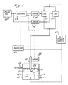
- a workpiece 10 is eroded by sparks and arcs between an electrode 11 and the workpiece itself.
- a tank 12 contains a dielectric liquid 13 in which the workpiece and one end of the electrode are immersed.
- the dielectric liquid which may be paraffin is pumped into an inlet 14 and recirculated after passing out of an outlet 15.
- the sparks and arcs are generated by an electrical circuit comprising a d.c. power supply 17, typically of 85 volts coupled by way of parallel-connected groups 18 and 19 of transistors to the electrode 11, the workpiece 10 being connected by way of a support 20 to one terminal of the power supply 17.
- a d.c. power supply 17 typically of 85 volts coupled by way of parallel-connected groups 18 and 19 of transistors to the electrode 11, the workpiece 10 being connected by way of a support 20 to one terminal of the power supply 17.
- a pulse oscillator 22 supplies triggering pulses for the transistor groups 18 and 19 by way of drive circuits 18' and 19' but whereas these triggering pulses are continually supplied to the group 19 the supply of such pulses to the group 18 is dependent on a signal from a control circuit 23. If in operation one of the following three conditions occurs: a gap 25 between the workpiece 10 and the electrode 11 closes completely so that a short circuit occurs; or closure of the gap 25 is imminent; or permanent arcing across the gap occurs, then the resulting voltage drop or current increase through the gap is sensed by a circuit 24 which by operating on the control circuit 23 inhibits triggering pulses reaching the transistor group 18. At other times the group 18 conducts and machining takes place.
- a typical machine includes a control for selecting the number of transistors in each group but for example the group 18 usually contains 80% of the total number of power transistors in use at any one time while the remaining 20% is in the group 19. Thus when any one of the above mentioned three conditions occurs 80% of the power supplied to the gap 25 will be removed.
- a machine operator may have the following controls: the duration of pulses from the oscillator 22, the mark space ratio of these pulses and the speed of feed of the electrode 11 towards the workpiece 10, this speed being controlled by a mechanical servo system labelled drive and designated 26 in Figure 1.
- the operator usually also has control of a number of transistors to be used at any time in addition to their grouping to allow the current to the gap to be varied, the transistors being connected in circuits which ensure that each transistor passes a known current.
- the operator sets up his controls according to instructions laid down in the manufacturer's manual of the E.D.M. machine being used.
- the operator has a monitoring meter indicating voltage across the gap 25 or current therethrough.
- the sensing circuit 24 cuts off, for example, 80% of the power to the gap as already described for an interval and then restores power. If an arc re-occurs immediately and the process of removing 80% of the power from the gap is again unsuccessful in preventing an arc restriking, the control circuit 23 causes the drive 26 to open the gap 25 greatly and the paraffin flowing through the tank flushes away any debris in the gap.
- a flushing tube (not shown) directed at the gap is usually provided, and when the gap is opened up a solenoid valve (not shown) is operated and a jet of paraffin flushes the debris away from the workpiece. Should these measures be unsuccessful the operator will reset the machine by, for example, reducing the drive speed of the workpiece or reducing the pulse length, or reducing the mark space ratio.
- a typical E.D.M. machine with controls of the above type is a Sparcatron Generator SPF 60W which has a gap voltage of 85 volts and a typical gap current during machining of 60 amps.
- the duration of each oscillator pulse can be set between 2 ⁇ sec and 2 msec and the mark space ratio can be set over the range in which the duration of the spaces is 0.2 to 4 times that of the marks.
- the present inventors have discovered that sound energy radiated from the region of the gap between the electrode and the workpiece is significantly different when the following four conditions: open circuit, sparking, arc and short circuit exist in the gap between the electrode and the workpiece.
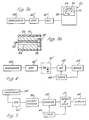
- Figure 2a shows an arbitrary, approximately 1:1 mark space ratio of voltage pulses applied across the gap between the electrode and the workpiece.
- An arbitrary pulse length of 2 milliseconds is shown.
- Figure 2d the four conditions mentioned above have been indicated and Figure 2b shows the sound signal amplitude occurring under these conditions.
- Figure 2 has been greatly simplified to remove the noise and other transients which occur in practical waveforms and also to select one sound frequency which occurs during arcing and one which occurs during sparking.
- That which is shown is due, for example, to background noise and vibration.
- a high amplitude high frequency sound signal occurs in the dielectric liquid whereas during the arcing condition only a relatively low frequency low amplitude sound signal is generated.
- the ratio of amplitudes and frequencies between the sound signals for sparking and arcing have been reduced in order to simplify the figure.
- FIG. 2e More typical but still simplified waveforms which might be obtained during machining are shown in Figure 2e, where the sound signals can be seen to change character at times from the high amplitude high frequency characteristic of sparking to the lower frequency low amplitude characteristic of arcing.
- Figure 2f shows high amplitude high frequency sound signals during all machining pulses and this constitutes a good machining situation.
- One aid to improved E.D.M. machining which is provided by the invention is a monitor which indicates clearly which of the four above mentioned conditions is currently occurring.
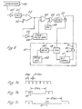
- an ultrasonic transducer 130 is coupled by way of an amplifier 40' and a detector circuit 41' to a milliammeter or millivolt- meter indicated schematically at 32.
- the transducer 130 includes a disc 90 (see Figure 3b) made from a piezoelectric ceramic, the disc being positioned in an insulating tube 91.
- the disc is 2 mm thick and 9 mm in diameter and consists of a modified lead zirconate titanate ceramic PZT-4, available from Verritron Limited, Thornhill, Victoria, England. Electrical connections 92 are made to the disc and the tube 91 is filled with an insulating material 93 such as an epoxy resin but a bore 94 with an enlarged portion 95 is provided.
- This transducer can be used from 10 Hz to 2 MHz and a slightly thinner disc is required for higher frequencies.
- the whole transducer is placed in a thin plastic envelope (not shown) particularly when it is to be used in the dielectric liquid.
- Electrical shielding may also be provided in the form of a copper tube around the tube 91, the copper tube being suitably earthed according to known shielding techniques.
- the transducer can be positioned anywhere in the dielectric liquid 13 (but not of course in gap 25), for example strapped to the workpiece 10 or the electrode 11, or it may be positioned outside the tank 12 preferably in contact therewith, or otherwise in the vicinity of the tank.
- a commercially available hydrophone such as the Type 8103 miniature hydrophone available from Brüel and Kjaer, of Naerum, Near Copenhagen, Denmark, may be used in the nominal frequency range 0.1 Hz to 200 KHz, although this hydrophone can be used at higher frequencies, for example 1 MHz. Many other suitable hydrophones are of course available.
- the amplifier 40' has a bandwidth covering the range 2 KHz to 70 KHz since the highest amplitude sound signal tends to move in this range as the duration of the voltage pulses applied to the gap change.
- the amplifier may include a variable frequency tuned stage to allow the highest amplitude signal to be followed under changing pulse conditions.
- transducers may be constructed using other piezoelectric crystals, ceramics or materials.
- the amplifier is followed by a diode detector in the form of a series diode and a shunt connected capacitor with a series resistor is used.
- the amplifier has an output signal amplitude dependent on input signal amplitude and preferably has a linear gain characteristic. Any suitable milliammeter can be connected at the output of the detector.
- the gain of the amplifier is set so that under best sparking conditions the pointer of the milliammeter takes up a position 33.
- a tuning control may also be provided and used in a similar way. It will then be found that arcing is indicated by the pointer taking up some such position as is indicated at 34, while open and short circuit conditions are indicated by the pointer being in position 35. A position where a reasonable amount of machining is taking place evenly is indicated by pointer position 36.
- pointer position 36 A position where a reasonable amount of machining is taking place evenly is indicated by pointer position 36.
- the operator adjusts the above machine controls for example: pulse duration, mark space ratio and electrode feed to keep the pointer as near position 33 as is possible.
- transducers and hydrophones may be as already described in connection with Figures 3a, and an amplifier followed by a detector as also described may be used.
- the transducer 130 is located in the region of the electrode or the workpiece and is coupled by way of the amplifier 40' to a detector 41' which may simply comprise the series diode and shunt capacitor shown.
- the amplifier 40 has an output signal amplitude dependent on input signal amplitude and preferably has a linear gain characteristic.
- the output of the detector is passed to an integrator 42 which integrates the d.c. signal corresponding to the envelope of the sound signal radiated from the gap.
- a meter 43 indicates the output of the integrator.
- a time 44 is provided to reset the integrator at manually selected intervals, for example in the range 2 to 20 minutes.
- the meter 43 includes a sample and hold circuit (not shown) which samples the integrator output immediately before it is reset.
- the integrator 42 is of the type which produces a digital output and this digital output is passed to a counter (neither the counter nor the digital display being shown). Again a sample and hold circuit is preferably used so that the display always shows the maximum count reached by the counter in the previous interval.
- FIG. 5 Another form of E.D.M. efficiency meter is shown in Figure 5 where as in Figure 4 the transducer 130 is coupled to the amplifier 40'.
- a schmidt trigger circuit 39 converts the signal from the amplifier 40' to rectangular pulses at a repetition frequency equal to the sound frequency. Its trigger level is set comparatively high so that it is triggered only by "efficient" sparking.
- the pulses produced are counted by a counter 45 which is reset at manually selectable intervals by a timer 46.
- a sample and hold circuit 47 Immediately before reset the counter output is sampled by a sample and hold circuit 47 and the number held by the sample and hold circuit is displayed by a display 48.
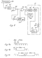
- the numerator in the above expression is given by the meter 43 and the display 48 and the denominator is a constant partially dependent on the time selected by the timer between resetting the integrator 42. For comparisons to be made, this constant does not have to be known but the time selected is kept constant. Alternatively the denominator can be found by a calibration in which "perfect" sparking is achieved for the whole integration time.
- a semiconductor rectifier (SCR) 50 is coupled in series with the d.c. supply 17 of Figure 1, the group of transistors 18, the electrode 11 and the workpiece 10. As before the group of transistors 18 are rendered alternately conducting and non-conducting by pulses from the oscillator 22. Thus all the items of equipment inside the dashed line 51 are part of an existing E.D.M. machine such as the Sparcatron Generator SPF 60W. Some other parts of the machine are not shown and some of these parts are not in operation in the modified machine.
- the resulting unidirectional voltage (the monitor signal) is compared in a comparator 52 with an adjustable reference level derived from a potentiometer 53. If the level of the monitor signal is high enough to indicate that sparking is occurring in the gap 25 the comparator passes a signal to an OR gate 54 and then to an AND gate 55. Since an SCR is triggered most effectively by 10 microsecond duration pulses an oscillator 56 is provided which generates such pulses. Each pulse is followed by a 5 microsecond gap, so that the oscillation period is 15 microseconds.
- sparking occurs 10 microsecond pulses reach a drive circuit 57 and gate the SCR 50 into its conducting condition.
- the gate 55 remains closed and the SCR 50 is not triggered.
- the SCR 50 is gated to conduction again after an interval which is sufficient to allow any ionisation channel formed during arcing to disperse, and on start up, by start pulses generated by a timer/pulse generator 58 under the control of the comparator 52 by way of an inverter 59.
- the generator 58 when the sound signal falls to a low level, the generator 58 generates a start pulse after a ten milliseconds interval and if the sound signal is at a low level start pulses are generated every ten milliseconds. Each start pulse causes a triggering pulse to be applied by the drive 57 to the SCR 50.
- the timer/pulse generator 58 may be a monostable circuit triggered to its unstable state at the start of the ten millisecond interval and emitting a pulse at the end of that interval when it returns to its stable state.
- the time constant of the detector 41 is long enough to maintain a signal at the output of the OR gate 54 during these intervals.
- FIG. 7a Some of the waveforms which occur in Figure 6 are shown in Figures 7a to 7c.
- the waveform of Figure 7a appears at the output of the group of transistors 18 and for example this waveform may be adjusted so that each pulse has a two millisecond duration with a 0.5 millisecond gap between pulses.
- the first start pulse from the oscillator 58 opens the gate 55 a series of 10 microsecond pulses passing through the gate 55 from the oscillator 56 fire the SCR 50 and for example the waveform of Figure 7b appears across the gap 25.
- arcing commences at the point 60, comparator 52 indicates the sound signal has fallen to a low level, the AND gate 55 closes and the SCR 50 only continues to conduct until current ceases to be passed from the group 18 of transistors at the end the then existing pulse.
- the inverter 59 triggers the pulse generator 58 so that after a period of 10 milliseconds a new start pulse is generated and the SCR 50 is again gated into conduction. It is during this period of 10 milliseconds that the ionisation channel of the arc disperses so that from then on sparking continues during pulses from the transistor group 18 without interruption as is shown by the continuing pulse train to the right of Figure 7b.
- arcing may start again at point 61 as shown in Figure 7c when the pulses applied to the gap 25 are once more interrupted for a further 10 milliseconds. Should several cycles of this condition occur the drive 26 (see Figure 1) comes into operation and the electrode 11 is withdrawn from the region of the workpiece so that the gap can be thoroughly flushed with paraffin and any swarf removed for example by using the flushing tube and solenoid valve mentioned above.
- the pulse waveform of Figure 7a can also be regarded as that appearing across the gap 25 when sparking occurs continuously during pulses and the SCR 50 is always gated into conduction at the beginning of a pulse from the transistor group 18.
- the amplifier 40 may be a type NE 592 r.f. amplifier, a type 710 comparator may be used for the comparator 52 and the oscillator 56 and pulse generator 58 may be type 555 timers.
- pulse lengths can be adjusted from 2 ⁇ sec to 2 msec it will be appreciated that whereas as shown in Figure 7a the point 60 may occur at a position in a pulse which significantly reduces the nominal 10 msec for the ionisation channel to disperse; under most pulse length settings this reduction will not be particularly significant even when the point 60 occurs near the beginning of a pulse.
- transistors of both groups 18 and 19 may be controlled by the outputs of the AND gate 55 of Figure 6.
- either one group of transistors may conduct continuously or both groups may be controlled to conduct under specific conditions.
- FIG 8 Another way in which the monitoring technique of the invention can be applied to an existing E.D.M. machine is indicated in Figure 8 where components 130, 40', 41', 52, 54, 58 and 59 perform the same functions as in Figure 7.
- the detector 41 has a time constant which allows the intervals between pulses from the oscillator 22 to be bridged.
- the dashed line 51 encloses components of a conventional E.D.M. machine.
- pulses are not produced at the output of the group 18 of transistors unless a sound signal indicating sparking is received or unless the oscillator 58 generates start pulses.
- the oscillator 22 is connected to an AND gate 64 which also receives an input from the OR gate 54.
- Figure 9c is an example of waveform across the gap 25 when an arc restrikes at the point 66 during the first pulse after the first 10 millisecond interval. Again if several of these cycles occur the drive 26 clears the electrode 11 from the region of the workpiece and the gap is thoroughly flushed before the electrode 11 is driven back into position and machining starts again.
- a low level sound signal causes the comparator 52 to trigger a pulse generator 70 to provide a pulse, which reaches the drive circuit 18' by way of an OR gate 71 and causes the transistor group 18 to conduct.
- a signal from the comparator 52 maintains a signal causing the transistors of the group 18 to continue conduction. Sparking continues in the gap until for example an arc occurs at point 73 in Figure 11 when the signal from the comparator ceases and the transistor group 18 immediately ceases to conduct.
- the waveform of Figure 11 falls to zero and a ten millisecond interval ensues for the arc ionisation channel to disperse, the start of this interval being triggered by the comparator 52 by way of the inverter 59 and ending when the pulse generator 70 applies a start pulse to the OR gate 71.
- This process is continuous as indicated in Figure 11 where a further arc occurring at point 74 is also shown.
- the waveform shown in Figure 11 is by way of illustration and in fact, of course, sparking would occur for a much greater portion of any machining time. Again provision is made for flushing the gap if arcing cycles of short period occur continually.
- Coarse and fine machining used at the beginning and end of a machining operation are often controlled by using long drive pulses to start and short pulses at the end. This adjustment is not available in the arrangement of Figure 10, since drive is applied at all times in which sparking occurs. However coarse and fine machining is achieved by adjustment of the power applied to the gap, for example by controlling the number of transistors in operation in the group 18.
- the arrangement of Figure 10 can be further modified by replacing the d.c. supply 17 and the groups of transistors 18 and 19 by an SCR bridge (not shown) with an a.c. supply connected across two terminals and the electrode and workpiece connected across opposite terminals.
- the four SCRs of the bridge are then directly triggered by the output from the gate 71 by way of a drive circuit but of course only those correctly poled by the supply at that time conduct.
- the SCRs can be replaced by SCSs with the advantage that arcing can be made to cease directly it is detected by switching off those SCSs which are conducting.
- control derived from sound monitoring
- controls the voltage waveform across the gap between the electrode and the workpiece it can of course also or alternatively be used to control other parameters of machining, notably the speed of feed of the electrode 11 towards the workpiece 10 as achieved by the drive 26.
- a logic circuit may be provided to control the feed rate, the logic circuit making adjustment when cycles ending with arcing occur at a frequency which is considered too high. Conversely if sparking is found to be continuous then the feed rate is increased until the point where arcing begins to occur occasionally.
- the adaptive control operated by the monitoring of the invention can be used to control pulse length and mark space ratio, gap opening and gap flushing, and gap current. It will be apparent to those skilled in the art how these parameters should be adjusted and how logic circuits for that adjustment can be designed.
- Both sound and optical radiation may be used to monitor the purity of the dielectric liquid by positioning a source of radiation and a receiver so that radiation has to pass through the liquid to reach the receiver from the source.
- the output of the receiver may then be applied to the microprocessor as one of the signals to be taken into account in controlling the E.D.M. machine.
Landscapes
- Engineering & Computer Science (AREA)
- Mechanical Engineering (AREA)
- Electrical Discharge Machining, Electrochemical Machining, And Combined Machining (AREA)
Applications Claiming Priority (2)
| Application Number | Priority Date | Filing Date | Title |
|---|---|---|---|
| GB51714/77A GB1604399A (en) | 1977-12-13 | 1977-12-13 | Methods for monitoring electrical discharge machining and apparatus for such machining |
| GB5171477 | 1977-12-13 |
Publications (2)
| Publication Number | Publication Date |
|---|---|
| EP0007965A1 EP0007965A1 (en) | 1980-02-20 |
| EP0007965B1 true EP0007965B1 (en) | 1982-05-19 |
Family
ID=10461100
Family Applications (1)
| Application Number | Title | Priority Date | Filing Date |
|---|---|---|---|
| EP78900289A Expired EP0007965B1 (en) | 1977-12-13 | 1978-12-08 | Improvements in methods and apparatus for electrical discharge machining |
Country Status (7)
| Country | Link |
|---|---|
| US (1) | US4348573A (OSRAM) |
| EP (1) | EP0007965B1 (OSRAM) |
| JP (1) | JPS54500082A (OSRAM) |
| DE (1) | DE2861859D1 (OSRAM) |
| GB (1) | GB1604399A (OSRAM) |
| IT (1) | IT1108381B (OSRAM) |
| WO (1) | WO1979000380A1 (OSRAM) |
Families Citing this family (13)
| Publication number | Priority date | Publication date | Assignee | Title |
|---|---|---|---|---|
| DE3212751A1 (de) * | 1981-04-15 | 1982-12-02 | National Research Development Corp., London | Verfahren und einrichtung zum abtragen von werkstoff von einem elektrisch leitenden werkstueck |
| CH655032A5 (fr) * | 1982-06-30 | 1986-03-27 | Mitsubishi Electric Corp | Machine a decharge electrique pour electro-erosion. |
| CH661228A5 (de) * | 1982-08-02 | 1987-07-15 | Mitsubishi Electric Corp | Funkenerosionsmaschine mit einer elektrode zum bearbeiten eines werkstueckes. |
| JPS61173821A (ja) * | 1985-01-24 | 1986-08-05 | Amada Co Ltd | 放電加工装置 |
| US5496984A (en) * | 1992-01-07 | 1996-03-05 | Mitsubishi Denki Kabushiki Kaisha | Electrical discharge machine and machining method therefor |
| US5360957A (en) * | 1992-06-11 | 1994-11-01 | General Electric Company | Controlled apparatus for electrical discharge machining |
| US6385500B1 (en) | 1999-04-16 | 2002-05-07 | Cummins Engine Company, Inc. | Hybrid servomechanism for micro-electrical discharge machining |
| GB2363749A (en) * | 2000-06-23 | 2002-01-09 | Univ Nottingham Trent | Acoustic feedback in the control of electrical discharge machining |
| US7041933B2 (en) * | 2003-04-14 | 2006-05-09 | Meyer Tool, Inc. | Complex hole shaping |
| WO2011004426A1 (ja) * | 2009-07-07 | 2011-01-13 | 三菱電機株式会社 | ワイヤ放電加工装置 |
| DE102011004799B4 (de) * | 2011-02-25 | 2012-09-27 | Varta Microbattery Gmbh | Statusindikator für temperaturempfindliche Güter |
| US20150101604A1 (en) * | 2013-05-29 | 2015-04-16 | David Bruce Crosbie | Nitric Oxide Generator and Inhaler |
| JP2018024025A (ja) * | 2016-08-08 | 2018-02-15 | ファナック株式会社 | 放電加工機 |
Family Cites Families (13)
| Publication number | Priority date | Publication date | Assignee | Title |
|---|---|---|---|---|
| GB640188A (en) | 1946-11-06 | 1950-07-12 | Bbc Brown Boveri & Cie | Improvements in and relating to the determination of electric discharge |
| GB953441A (en) | 1960-01-25 | 1964-03-25 | Ass Elect Ind | Improvements in and relating to apparatus for testing electric insulation |
| US3253457A (en) | 1961-12-15 | 1966-05-31 | Westinghouse Electric Corp | Apparatus for locating trouble sources which generate ultrasonic vibrations |
| US3430136A (en) | 1965-12-21 | 1969-02-25 | Gen Electric | Test equipment for identification and location of electrical faults in fluid-filled electric apparatus |
| DE1806648A1 (de) * | 1968-11-02 | 1970-05-21 | Erdmann Jesnitzer Dr Ing Habil | Vorrichtung und Verfahren zur Kontrolle von Elektroschweissverfahren |
| USRE29398E (en) | 1969-03-13 | 1977-09-13 | Servosystem for electrical machining processes | |
| DE1919034A1 (de) * | 1969-04-15 | 1970-10-22 | Erdmann Jesnitzer Dr Ing Habil | Vorrichtung zur Kontrolle von Elektroschweissverfahren |
| GB1320136A (en) | 1969-09-09 | 1973-06-13 | English Electric Co Ltd | Testing electrical insulation and locating faults therein |
| US3816692A (en) * | 1972-03-02 | 1974-06-11 | S Ratmansky | Electrical discharge machining efficiency and safety monitoring system |
| USRE27707E (en) | 1972-08-11 | 1973-07-24 | Method and apparatus for detecting and controlling through pulse energy variations arcing conditions in an edm process | |
| DE2315323B2 (de) | 1973-03-23 | 1980-06-19 | Siemens Ag, 1000 Berlin Und 8000 Muenchen | Einrichtung zur Erfassung dielektrischer Durchschläge in metallgekapselten Hochspannungsschaltanlagen |
| GB1492027A (en) | 1974-05-23 | 1977-11-16 | Deckel Ag Friedrich | Electrical discharge machining |
| CH585608A5 (OSRAM) | 1973-12-04 | 1977-03-15 | Deckel Ag Friedrich |
-
1977
- 1977-12-13 GB GB51714/77A patent/GB1604399A/en not_active Expired
-
1978
- 1978-12-08 JP JP50015478A patent/JPS54500082A/ja active Pending
- 1978-12-08 WO PCT/GB1978/000052 patent/WO1979000380A1/en not_active Ceased
- 1978-12-08 US US06/154,408 patent/US4348573A/en not_active Expired - Lifetime
- 1978-12-08 EP EP78900289A patent/EP0007965B1/en not_active Expired
- 1978-12-08 DE DE7878900289T patent/DE2861859D1/de not_active Expired
- 1978-12-13 IT IT69843/78A patent/IT1108381B/it active
Also Published As
| Publication number | Publication date |
|---|---|
| JPS54500082A (OSRAM) | 1979-12-06 |
| EP0007965A1 (en) | 1980-02-20 |
| DE2861859D1 (en) | 1982-07-08 |
| IT1108381B (it) | 1985-12-09 |
| GB1604399A (en) | 1981-12-09 |
| IT7869843A0 (it) | 1978-12-13 |
| US4348573A (en) | 1982-09-07 |
| WO1979000380A1 (en) | 1979-06-28 |
Similar Documents
| Publication | Publication Date | Title |
|---|---|---|
| EP0007965B1 (en) | Improvements in methods and apparatus for electrical discharge machining | |
| US4236057A (en) | Apparatus for detecting gap conditions in EDM processes with monitoring pulses | |
| US4338504A (en) | Arc prevention and detection electrical discharge machine servo control system | |
| EP1537934B1 (en) | Electric discharge machine | |
| US3758739A (en) | Iece apparatus for removing material from an electrically conducting workp | |
| US4366360A (en) | Method of and apparatus for determining relative position of a tool member to a workpiece in a machine tool | |
| US4700038A (en) | Method and apparatus for measuring the rate of wear of an EDM electrode tool | |
| El-Menshawy et al. | The use of acoustic techniques for monitoring and controlling the EDM process | |
| EP0007968A1 (en) | IMPROVEMENTS IN METHODS AND APPARATUS FOR ELECTROEROSION MACHINING. | |
| GB2075401A (en) | Improvements in methods and apparatus for electrical discharge machining | |
| EP0061852A2 (en) | Self starting current controlled discharge bonding wire ball maker | |
| US3287537A (en) | Machining by sparking | |
| US3727024A (en) | Electrical discharge machining servo control circuit | |
| JPH0659572B2 (ja) | ワイヤカット放電加工装置 | |
| JPH0661659B2 (ja) | ワイヤカツト放電加工装置 | |
| JPS6036894B2 (ja) | 放電加工における間隙制御装置 | |
| JPH0661662B2 (ja) | ワイヤカツト放電加工装置 | |
| JPH0661658B2 (ja) | ワイヤカツト放電加工装置 | |
| JP2587956B2 (ja) | ワイヤ放電加工機の制御装置 | |
| JPS61111839A (ja) | ワイヤカツト放電加工装置 | |
| JPS61111833A (ja) | ワイヤカツト放電加工装置 | |
| KR820002134B1 (ko) | Edm처리에서 모니터링펄스로 갭상태를 검출하는 방법 | |
| JPH0661661B2 (ja) | ワイヤカツト放電加工装置 | |
| SU965667A1 (ru) | Устройство дл сварки давлением | |
| JPS61111829A (ja) | ワイヤカツト放電加工装置 |
Legal Events
| Date | Code | Title | Description |
|---|---|---|---|
| PUAI | Public reference made under article 153(3) epc to a published international application that has entered the european phase |
Free format text: ORIGINAL CODE: 0009012 |
|
| AK | Designated contracting states |
Designated state(s): CH DE |
|
| 17P | Request for examination filed | ||
| GRAA | (expected) grant |
Free format text: ORIGINAL CODE: 0009210 |
|
| AK | Designated contracting states |
Designated state(s): CH DE |
|
| REF | Corresponds to: |
Ref document number: 2861859 Country of ref document: DE Date of ref document: 19820708 |
|
| PGFP | Annual fee paid to national office [announced via postgrant information from national office to epo] |
Ref country code: CH Payment date: 19841214 Year of fee payment: 7 |
|
| PGFP | Annual fee paid to national office [announced via postgrant information from national office to epo] |
Ref country code: DE Payment date: 19850219 Year of fee payment: 7 |
|
| PG25 | Lapsed in a contracting state [announced via postgrant information from national office to epo] |
Ref country code: DE Effective date: 19870901 |
|
| PG25 | Lapsed in a contracting state [announced via postgrant information from national office to epo] |
Ref country code: CH Effective date: 19891231 |
|
| REG | Reference to a national code |
Ref country code: CH Ref legal event code: PL |
|
| PLBE | No opposition filed within time limit |
Free format text: ORIGINAL CODE: 0009261 |
|
| STAA | Information on the status of an ep patent application or granted ep patent |
Free format text: STATUS: NO OPPOSITION FILED WITHIN TIME LIMIT |