EP0007928B1 - Appareil de commande de chaleur - Google Patents
Appareil de commande de chaleur Download PDFInfo
- Publication number
- EP0007928B1 EP0007928B1 EP19780300273 EP78300273A EP0007928B1 EP 0007928 B1 EP0007928 B1 EP 0007928B1 EP 19780300273 EP19780300273 EP 19780300273 EP 78300273 A EP78300273 A EP 78300273A EP 0007928 B1 EP0007928 B1 EP 0007928B1
- Authority
- EP
- European Patent Office
- Prior art keywords
- controller
- motor
- interval
- adjusting
- current
- Prior art date
- Legal status (The legal status is an assumption and is not a legal conclusion. Google has not performed a legal analysis and makes no representation as to the accuracy of the status listed.)
- Expired
Links
Images

Classifications
-
- G—PHYSICS
- G05—CONTROLLING; REGULATING
- G05D—SYSTEMS FOR CONTROLLING OR REGULATING NON-ELECTRIC VARIABLES
- G05D23/00—Control of temperature
- G05D23/19—Control of temperature characterised by the use of electric means
- G05D23/1951—Control of temperature characterised by the use of electric means with control of the working time of a temperature controlling device
Definitions
- the present invention relates generally to an apparatus for controlling the electric current supplied to a heating element and, more particularly, to such an apparatus for use in an electric kiln adapted to fire ceramic ware.
- U.S. Patent No. 3,855,452 to Flasza et al discloses another control system for a ceramic kiln which again utilizes quite expensive solid-state timing circuits and logic blocks. Moreover, the use of such solid-state circuits in a control system mounted on or near a ceramic kiln is disadvantageous since such circuits are temperature sensitive and may degrade under the operating temperatures achieved by the kiln.
- U.S. Patent No. 1,861,472 to Glitzke discloses a device for gradually increasing the temperature in a furnace comprising a clock motor which progressively cuts out sections of a variable resistance element to thereby increase the electric current being supplied to the heating element. However, such a variable resistance element is often expensive and prone to failure.
- French Patent Application No. 2,304,239 discloses an oven having two heating elements, one connected in a feedback loop with a thermostat and another connected to a pulse controller having contacts actuated by a bimetallic strip timing device. This specification is concerned with producing an oven in which the vertical temperature distribution can be varied according to culinary requirements.
- U.S. Patent No. 3,588,419 discloses a temperature control device comprising a periodic on-off controller which supplies heating current to the resistive heating element of a furnace.
- This circuit like that of Allen (mentioned above) uses additional complex circuitry producing an electrical signal which is combined with that of a thermocouple to provide feedback from the control environment.
- a reference potentiometer provides one of the signals to the controller and the potentiometer is controlled by a motor which is in turn controlled by a fixed frequency oscillator. This oscillator thus defines a constant rate of temperature increase in the furnace regardless of changing heat requirements of the articles to be heated.
- it uses relatively expensive electronic timing circuits, potentiometers and other electrical components which render it unsuitable for incorporation in kilns for home manufacture of ceramics.
- an automatic heat control apparatus in which a periodic on-off controller for supplying current to an electrical heating element is coupled to motor means for automatically actuating adjustment means of the controller over a predetermined time period to gradually increase the duration of the on interval relative to the off interval thereby to control the rate of temperature increase produced by the heating element, the motor means being the sole means for automatically actuating the adjustment means, and wherein the controller includes a thermal-mechanical timing mechanism responsive to fluctuations of electric current or voltage applied to the heating element.
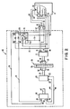
- Control unit 2 suitably supplies electric current to a conventional electric kiln or furnace 4 having electrical resistance heating elements 6 ending in terminals 8 which are connected by conductors 9 to control unit 2.
- Control unit 2 is particularly adapted for use with kilns 4 meant for home use by a hobbyist or in a small business.
- unit 2 is not limited for use with such kilns, but may be used to control the rate of temperature increase in any type of electric heating element.
- Control unit 2 comprises a suitably shaped housing or enclosure 10 which contains therein the various elements of unit 2.
- Control unit 2 further includes a first power controller 12 of the periodic on-off type.
- Controller 12 has input terminals 14 connected to the terminals 15 of an AC voltage source, and output terminals 16 connected to the kiln heating elements 6 by conductors 9.
- controller 12 has a rotatable adjusting shaft 18 for changing the duration of the on interval relative to the off interval in controller 12 as described hereafter.
- Controller 12 is preferably a Robertshaw Infinite Control, Models Nos. INF24031B, )NF12032B or their equivalent. Basically, these power controllers have a plurality of cycles each comprising an on interval during which the controller passes current through the unit to its output terminals and an off interval during which no current is allowed to pass through the unit.
- Such controllers mechanically comprise a bimetallic control arm having a heater wrapped therearound which is energized whenever power passes through the unit during the on interval. A magnet normally holds the control arm engagement with an electrical contact allowing the current to pass through the unit from the voltage source to the output terminals.
- Control unit 2 further comprises a continuous speed AC electric timing motor 20 having terminals 22 for connection to a power source and a rotatable output shaft 24.
- Motor 20 and controller 12 are suitably supported and arranged inside enclosure 10 so that output shaft 24 and adjusting shaft 18 are oriented towards one another and spaced a suitable distance apart.
- An integrally molded thumbwheel 26 having a circular wheel portion 28 and two hollow sleeves 30 extending from either side thereof is rotatably supported inside enclosure 10 and is arranged between motor 20 and controller 12. Adjusting shaft 18 is inserted into one of the hollow sleeves 30 and secured thereto by a setscrew 32 contacting a flat portion on shaft 18. Similarly, output shaft 24 is inserted into the other hollow sleeve 30 and secured thereto by a setscrew 32.
- thumbwheel 26 suitably extends through the surface of enclosure 10 and has appropriate indicia printed thereon to visually indicate to the operator the level of heating taking place in kiln 4. Moreover, since thumbwheel 26 extends through the surface of enclosure 10, it may be manually rotated by the operator to override the control unit 2 as will be explained in more detail hereafter.
- a second power controller 36 having input terminals 38, output terminals 40 and a rotatable adjusting shaft 42 is supported inside enclosure 10 with shaft 42 protruding to the outside of enclosure 10 where it may be manually rotated.
- Controller 36 is a periodic on-off controller of the same type as controller 12.
- Output terminals 40 of controller 36 are connected by conductors 44 to terminals 22 of motor 20.
- input terminals 38 of controller 36 are connected by conductors 46 to a limit switch 48.
- Limit switch 48 is connected by conductors 49 to the terminals 50 of a conventional AC power source.
- Power source 50 may be the same source as power source 15 or it may be a different source as illustrated herein. In any event, sources 15 and 50 comprise conventional 110 VAC or 220 VAC house current.
- a cam 52 is integrally formed on the outer surface of one of the hollow sleeves 30 of thumbwheel 26.
- Cam 52 has a mechanical connection 54 with limit switch 48 controlling the application of power to controller 36 as will be described hereafter.
- cam 52 and switch 48 have been shown in Figure 1 for the purpose of illustration as separated inside enclosure 10, they preferably are positioned adjacent one another so that cam 52 directly actuates switch 48 without any intervening linkage.
- switch 48 could include a spring- biased button which is directly actuated by cam 52 to open switch 48 whenever thumbwheel 26 reaches a certain angular position inside enclosure 10.
- a temperature sensing element 55 is included inside kiln 4 and is connected by conductors 56 to an on-off control unit 57 that is connected in series in the conductors connecting voltage source 15 to controller 12. Whenever the temperature sensing element 55 detects that a sufficient temperature has been reached inside kiln 4 to complete proper firing of the ceramic ware, it activates control unit 57 through conductors 56 to disconnect controller 12 from power source 15. Kiln 4 will then slowly cool down to ambient temperature. Sensing element 55 and control unit 57 may comprise a Dawson kiln sitter or its equivalent.
- first power controller 12 is energized by either a 110 or 220 volt power source 15 for supplying current to heating elements 6.
- Thumbwheel 26 is initially rotated to a zero position, as indicated by the indicia on wheel portion 28, where adjusting shaft 18 is so positioned that the on interval of controller 12 has its minimum duration.
- controller 36 will intermittently energize motor 20 in accordance with whatever duration of on interval has been selected by the rotation of adjusting shaft 42.
- motor 20 intermittently rotates adjusting shaft 18 through thumbwheel 26 such that the duration of the on interval of controller 12 is intermittently increased while the duration of the off interval is intermittently decreased to provide a time proportional increase in the amount of electric current applied by controller 12 to heating elements 6 to slowly increase the temperature in kiln 4.
- cam 52 is so positioned to energize limit switch 48 thereby stopping the flow of power to the first controller 36 and stopping further rotation of motor 20. Therefore, automatic heat control unit 2 will be at its maximum full on position only after a predetermined time period during which shaft 18 is slowly and intermittently rotated by motor 20.
- control unit 2 of the present invention has an extremely low cost because it utilizes elements, such as time proportional power control units 12 and 36, which are extremely inexpensive and readily available. Control unit 2 does not utilize expensive variable reostats to gradually increase the current applied to the heating elements 6, but rather merely applies a constant current to the heating elements through power controller 12 and only adjusts the proportion of the on time versus the off time.
- the rate at which the temperature is increased in kiln 4 can be varied within wide limits by adjusting the average speed of rotation of motor 20.
- motor 20 is not a variable speed motor which is more expensive than the constant speed motor 20 used herein, its average speed can still be varied by adjusting the duration of the on interval relative to the off interval in second controller 36.
- the average speed of rotation of motor 20 will increase thereby increasing the rotation of shaft 18 and causing a faster rise in temperature in kiln 4.
- the average speed of rotation of motor 20 will decrease thereby causing a slower rate of temperature increase in kiln 4.
- the operator may override motor 20 to turn the heating level of control unit 2 up or down by manually rotating thumbwheel 26 in one direction or the other.
- control unit 62 comprises all the elements of control unit 2 except that the mechanically actuated limit switch 48 for controllimg the power input to second power controller 36 has been replaced by an electrical relay switch 64 having a set of normally closed contacts 66 and a set of normally open contacts 68.
- relay 64 has a coil 70 and an auxiliary pair of terminals 72 for connection to voltage source 15 by conductors 71.
- Coil 70 is connected by conductors 73 to the output terminals 16 of first power controller 12. Coil 70 will therefore be intermittently energized when controller 12 is intermittently energized during its on interval.
- Input terminals 38 of second controller 36 are connected by conductors 74 to the normally closed contacts 66 of relay 64.
- normally closed contacts 66 supplying the electrical power to controller 36 will be opened thereby disabling controller 36 from energizing motor 20.
- normally closed contacts 66 will be continuously opened thereby continuously disabling motor 20 from running in the same manner as limit switch 48.
- normally open contacts 68 in relay 64 can be connected to additional heating elements 6 inside kiln 4 via conductors 9 if it is desired to supply additional electric power from the two auxiliary terminals 72 in relay 64.
- Contacts 68 would be used whenever the amperage requirements of elements 6 exceed the capacity of controller 12 by itself which is approximately 15 amps. However, contacts 68 are still controlled by controller 12 since they will be closed only whenever coil 70 is energized by controller 12 during its on interval.
- Relay 64 may be a Potter and Brumfield Model No. PR11AYO relay or its equivalent.
- second controller 36 is shown in Figure 1 as being energized from power source 50, it could be energized through a feedback relationship with first controller 12. In such an event, conductors 49 would be connected to output terminals 16 of controller 12. Current would thus be applied to controller 36 during the on intervals of controller 12 which are at a minimum when control unit 2 is first turned on and continually increase until they are of constant duration. Thus, the amount of current delivered by controller 36 to motor 20 will be gradually increased over time so that motor 20 has a minimum average speed when unit 2 has just started and kiln 4 is cold and a maximum average speed only after kiln 4 has been heated to some degree. Such an arrangement further lessens the risk of breaking the ceramic material being fired in kiln 4.
- Control unit 62 shown in Figure 2 also illustrates a feedback relationship between controllers 12 and 36 through relay 64.
- relay 64 causes current to be applied to controller 36 in an inverse manner to that just described, i.e., average speed of motor 20 will be greatest when unit 62 is first turned on and the intervals of controller 12 are of minimum duration.
- the control unit 62 will still give good results in controlling the heating of kiln 4.
- controller 12 and/or controller 36 may have a pilot light connected in parallel with the input terminals thereof to visually indicate that power is being supplied to the heat control unit.
- pilot lights are not necessary to the present invention whose scope, therefore, is to be limited only by the appended claims.
Claims (13)
Priority Applications (2)
| Application Number | Priority Date | Filing Date | Title |
|---|---|---|---|
| EP19780300273 EP0007928B1 (fr) | 1978-08-09 | 1978-08-09 | Appareil de commande de chaleur |
| DE7878300273T DE2862304D1 (en) | 1978-08-09 | 1978-08-09 | Heat control apparatus |
Applications Claiming Priority (1)
| Application Number | Priority Date | Filing Date | Title |
|---|---|---|---|
| EP19780300273 EP0007928B1 (fr) | 1978-08-09 | 1978-08-09 | Appareil de commande de chaleur |
Publications (2)
| Publication Number | Publication Date |
|---|---|
| EP0007928A1 EP0007928A1 (fr) | 1980-02-20 |
| EP0007928B1 true EP0007928B1 (fr) | 1983-08-17 |
Family
ID=8185992
Family Applications (1)
| Application Number | Title | Priority Date | Filing Date |
|---|---|---|---|
| EP19780300273 Expired EP0007928B1 (fr) | 1978-08-09 | 1978-08-09 | Appareil de commande de chaleur |
Country Status (2)
| Country | Link |
|---|---|
| EP (1) | EP0007928B1 (fr) |
| DE (1) | DE2862304D1 (fr) |
Families Citing this family (2)
| Publication number | Priority date | Publication date | Assignee | Title |
|---|---|---|---|---|
| DE3803674A1 (de) * | 1988-02-06 | 1989-08-17 | Henneberg & Brunner Entwicklun | Verfahren zur erzeugung eines elektrischen steuersignals in einem aufbereitungsgeraet fuer medizinisch-therapeutische packungsmassen |
| US4899031A (en) * | 1988-11-14 | 1990-02-06 | David F. Dyer | Pulsed electrical heating of concrete |
Family Cites Families (6)
| Publication number | Priority date | Publication date | Assignee | Title |
|---|---|---|---|---|
| US3321608A (en) * | 1963-04-15 | 1967-05-23 | Packard Instrument Co Inc | Digital programmer for controlling variable condition |
| US3293406A (en) * | 1964-12-14 | 1966-12-20 | Aluminium Lab Ltd | Method and apparatus for baking carbonaceous linings |
| US3479487A (en) * | 1967-05-04 | 1969-11-18 | Milton Stoll | Temperature controller employing closed loop feedback and incremental programming |
| FR1598167A (fr) * | 1968-09-10 | 1970-07-06 | ||
| US3948441A (en) * | 1974-08-13 | 1976-04-06 | Robertshaw Controls Company | Time variable thermostat |
| FR2304239A1 (fr) * | 1975-03-11 | 1976-10-08 | Rosieres Usines | Dispositif de commande a repartition de chaleur variable notamment pour fours et cuisinieres electriques |
-
1978
- 1978-08-09 EP EP19780300273 patent/EP0007928B1/fr not_active Expired
- 1978-08-09 DE DE7878300273T patent/DE2862304D1/de not_active Expired
Also Published As
| Publication number | Publication date |
|---|---|
| DE2862304D1 (en) | 1983-09-22 |
| EP0007928A1 (fr) | 1980-02-20 |
Similar Documents
| Publication | Publication Date | Title |
|---|---|---|
| US3364338A (en) | Oven temperature control | |
| US2767293A (en) | Temperature control system | |
| US4184067A (en) | Heat control apparatus | |
| US3737622A (en) | Temperature-regulating apparatus | |
| EP0007928B1 (fr) | Appareil de commande de chaleur | |
| EP0244268A3 (fr) | Dispositif de commande de puissance pour commande de température | |
| CA1114876A (fr) | Dispositif thermostatique | |
| SE7700658L (sv) | Forfarande och anordning for reglering av temperaturforloppet i en krukmakarugn eller liknande | |
| MXPA06001473A (es) | Sistema de control para la operacion de un horno de cocina. | |
| US1416009A (en) | Control system for electric ranges | |
| CN201106865Y (zh) | 一种燃气具用控制装置 | |
| GB1446494A (en) | Melt cycle control system | |
| US3560711A (en) | Oven control system and parts therefor or the like | |
| US2429475A (en) | Control device for heater circuits | |
| JPS6112354B2 (fr) | ||
| JPS6433465A (en) | Hot water supplier | |
| ES8100729A1 (es) | Perfeccionamientos en los sistemas de regulacion de tempera-tura para aparatos de calefaccion electrica | |
| GB2280099A (en) | Thermostatically controlled frying pan | |
| US3201565A (en) | Oven heating system | |
| GB2252647A (en) | Power control circuits for electric heaters | |
| US3077529A (en) | Domestic appliance | |
| GB2177271A (en) | Control means for electrical heating means of a cooker | |
| GB1190323A (en) | Control means for Electrical Storage Heaters | |
| JPS6414551A (en) | Petroleum heating device | |
| GB907565A (en) | Improvements in temperature responsive control |
Legal Events
| Date | Code | Title | Description |
|---|---|---|---|
| PUAI | Public reference made under article 153(3) epc to a published international application that has entered the european phase |
Free format text: ORIGINAL CODE: 0009012 |
|
| AK | Designated contracting states |
Designated state(s): CH DE FR GB NL SE |
|
| 17P | Request for examination filed | ||
| GRAA | (expected) grant |
Free format text: ORIGINAL CODE: 0009210 |
|
| AK | Designated contracting states |
Designated state(s): CH DE FR GB NL SE |
|
| REF | Corresponds to: |
Ref document number: 2862304 Country of ref document: DE Date of ref document: 19830922 |
|
| ET | Fr: translation filed | ||
| PLBE | No opposition filed within time limit |
Free format text: ORIGINAL CODE: 0009261 |
|
| STAA | Information on the status of an ep patent application or granted ep patent |
Free format text: STATUS: NO OPPOSITION FILED WITHIN TIME LIMIT |
|
| 26N | No opposition filed | ||
| PGFP | Annual fee paid to national office [announced via postgrant information from national office to epo] |
Ref country code: SE Payment date: 19900731 Year of fee payment: 13 |
|
| PGFP | Annual fee paid to national office [announced via postgrant information from national office to epo] |
Ref country code: DE Payment date: 19900828 Year of fee payment: 13 |
|
| PGFP | Annual fee paid to national office [announced via postgrant information from national office to epo] |
Ref country code: NL Payment date: 19900831 Year of fee payment: 13 |
|
| PGFP | Annual fee paid to national office [announced via postgrant information from national office to epo] |
Ref country code: CH Payment date: 19901024 Year of fee payment: 13 |
|
| PGFP | Annual fee paid to national office [announced via postgrant information from national office to epo] |
Ref country code: GB Payment date: 19910717 Year of fee payment: 14 |
|
| PG25 | Lapsed in a contracting state [announced via postgrant information from national office to epo] |
Ref country code: SE Effective date: 19910810 |
|
| PGFP | Annual fee paid to national office [announced via postgrant information from national office to epo] |
Ref country code: FR Payment date: 19910822 Year of fee payment: 14 |
|
| PG25 | Lapsed in a contracting state [announced via postgrant information from national office to epo] |
Ref country code: CH Effective date: 19910831 |
|
| PG25 | Lapsed in a contracting state [announced via postgrant information from national office to epo] |
Ref country code: NL Effective date: 19920301 |
|
| NLV4 | Nl: lapsed or anulled due to non-payment of the annual fee | ||
| REG | Reference to a national code |
Ref country code: CH Ref legal event code: PL |
|
| PG25 | Lapsed in a contracting state [announced via postgrant information from national office to epo] |
Ref country code: DE Effective date: 19920501 |
|
| PG25 | Lapsed in a contracting state [announced via postgrant information from national office to epo] |
Ref country code: GB Effective date: 19920809 |
|
| GBPC | Gb: european patent ceased through non-payment of renewal fee |
Effective date: 19920809 |
|
| PG25 | Lapsed in a contracting state [announced via postgrant information from national office to epo] |
Ref country code: FR Effective date: 19930430 |
|
| REG | Reference to a national code |
Ref country code: FR Ref legal event code: ST |
|
| EUG | Se: european patent has lapsed |
Ref document number: 78300273.6 Effective date: 19920306 |