EP0007708B1 - Gehhilfe - Google Patents
Gehhilfe Download PDFInfo
- Publication number
- EP0007708B1 EP0007708B1 EP79301255A EP79301255A EP0007708B1 EP 0007708 B1 EP0007708 B1 EP 0007708B1 EP 79301255 A EP79301255 A EP 79301255A EP 79301255 A EP79301255 A EP 79301255A EP 0007708 B1 EP0007708 B1 EP 0007708B1
- Authority
- EP
- European Patent Office
- Prior art keywords
- frame
- wheels
- wheel
- front legs
- aid
- Prior art date
- Legal status (The legal status is an assumption and is not a legal conclusion. Google has not performed a legal analysis and makes no representation as to the accuracy of the status listed.)
- Expired
Links
Images

Classifications
-
- A—HUMAN NECESSITIES
- A61—MEDICAL OR VETERINARY SCIENCE; HYGIENE
- A61H—PHYSICAL THERAPY APPARATUS, e.g. DEVICES FOR LOCATING OR STIMULATING REFLEX POINTS IN THE BODY; ARTIFICIAL RESPIRATION; MASSAGE; BATHING DEVICES FOR SPECIAL THERAPEUTIC OR HYGIENIC PURPOSES OR SPECIFIC PARTS OF THE BODY
- A61H3/00—Appliances for aiding patients or disabled persons to walk about
- A61H3/04—Wheeled walking aids for disabled persons
-
- A—HUMAN NECESSITIES
- A61—MEDICAL OR VETERINARY SCIENCE; HYGIENE
- A61H—PHYSICAL THERAPY APPARATUS, e.g. DEVICES FOR LOCATING OR STIMULATING REFLEX POINTS IN THE BODY; ARTIFICIAL RESPIRATION; MASSAGE; BATHING DEVICES FOR SPECIAL THERAPEUTIC OR HYGIENIC PURPOSES OR SPECIFIC PARTS OF THE BODY
- A61H3/00—Appliances for aiding patients or disabled persons to walk about
- A61H2003/002—Appliances for aiding patients or disabled persons to walk about with attached or incorporated article carrying means
-
- A—HUMAN NECESSITIES
- A61—MEDICAL OR VETERINARY SCIENCE; HYGIENE
- A61H—PHYSICAL THERAPY APPARATUS, e.g. DEVICES FOR LOCATING OR STIMULATING REFLEX POINTS IN THE BODY; ARTIFICIAL RESPIRATION; MASSAGE; BATHING DEVICES FOR SPECIAL THERAPEUTIC OR HYGIENIC PURPOSES OR SPECIFIC PARTS OF THE BODY
- A61H3/00—Appliances for aiding patients or disabled persons to walk about
- A61H3/04—Wheeled walking aids for disabled persons
- A61H2003/046—Wheeled walking aids for disabled persons with braking means
-
- A—HUMAN NECESSITIES
- A61—MEDICAL OR VETERINARY SCIENCE; HYGIENE
- A61H—PHYSICAL THERAPY APPARATUS, e.g. DEVICES FOR LOCATING OR STIMULATING REFLEX POINTS IN THE BODY; ARTIFICIAL RESPIRATION; MASSAGE; BATHING DEVICES FOR SPECIAL THERAPEUTIC OR HYGIENIC PURPOSES OR SPECIFIC PARTS OF THE BODY
- A61H2201/00—Characteristics of apparatus not provided for in the preceding codes
- A61H2201/16—Physical interface with patient
- A61H2201/1602—Physical interface with patient kind of interface, e.g. head rest, knee support or lumbar support
- A61H2201/1614—Shoulder, e.g. for neck stretching
-
- A—HUMAN NECESSITIES
- A61—MEDICAL OR VETERINARY SCIENCE; HYGIENE
- A61H—PHYSICAL THERAPY APPARATUS, e.g. DEVICES FOR LOCATING OR STIMULATING REFLEX POINTS IN THE BODY; ARTIFICIAL RESPIRATION; MASSAGE; BATHING DEVICES FOR SPECIAL THERAPEUTIC OR HYGIENIC PURPOSES OR SPECIFIC PARTS OF THE BODY
- A61H2201/00—Characteristics of apparatus not provided for in the preceding codes
- A61H2201/16—Physical interface with patient
- A61H2201/1602—Physical interface with patient kind of interface, e.g. head rest, knee support or lumbar support
- A61H2201/1628—Pelvis
- A61H2201/1633—Seat
Definitions
- This invention concerns mobility aids, that is, devices for assisting the handicapped and/or infirm to move with a walking action: typical such devices are the stick, the crutch and the so-called “walking frame” and it is with the latter type of mobility aid that the invention is especially concerned.
- a typical walking frame comprises a four-legged tubular metal frame that is generally U-shaped in plan, being open at the rear to permit a user to enter and stand within the frame. It is necessary for the user repeatedly to lift the frame and move it an appropriate distance in the desired direction - an awkward and tiring action that is difficult or impossible for the relatively seriously handicapped or infirm to perform.
- Such frames may have braking arrangements for preventing movement of the frame upon application of an appropriate download to the frame.
- GB-A-1 342 397 discloses a walking frame equipped with wheels or casters that are mounted for limited upward movement in the legs of the frame, against the thrust of springs, so that when weight is applied to the frame the wheels move upwardly relative to lugs on the frame legs, the wheels or casters engaging these lugs so as to be braked against rotation.
- GB-A-1 373 593 describes a similar system using gliders instead of wheels.
- the gliders have a downwardly spring-loaded sleeve the lower end of which provides a gliding surface and that surrounds a plug of rubber or plastics material providing a gripping surface that is pressed into engagement with the ground when weight is put on the frame so as to cause the sleeve to be pressed upwardly relatively to the plug.
- Such wheeled etc. frames are, however, similarly difficult or impossible to use by the relatively seriously handicapped or infirm who need a large degree of support from the frames and must consequently lean very heavily thereon. Furthermore, such frames are not confidence-inspiring to use because of the possibility of the frame "running away" with the user.
- the present invention provides a mobility aid comprising a four-legged frame, the front legs of which have ground-engaging wheels with axes movable in the direction of the lengths of the front legs, and resilient means acting to urge said wheel axes downwardly of the front legs, characterised by the said wheel axes being movable in unison and by one-way wheel-driving means responsive to upwards movement of said wheel axes relative to said front legs to cause forwards rotational motion of the wheels.
- the arrangement of the wheels, the wheel-driving means and said resilient means is such that in the freestanding condition the latter lift the front of the frame so that when the frame is pressed down by the user bearing down on an appropriate part of the frame, the wheels are caused to rotate in the sense to cause forwards movement of the aid, the rear legs dragging as a result.
- a repeated bearing down action easily accomplished even by the severly handicapped, thus results in forward motion of the aid without requiring lifting of the aid by the user.
- This motion is easily controlled because part of the download applied by the user to the frame is transmitted to the rear legs of the aid and therefore results in braking resistance to forward motion; the proportion of the total download that generates braking resistance in this way is easily, and substantially instinctively, varied by the user in a way that inspires the confidence of the user.
- the wheels are constrained to move in unison relatively to the front legs so that even if the rear legs are raised clear of the ground there is no tendency to lateral tilting of the frame in response to uneven loading of the frame, as for instance might arise from stumbling by the user or from asymmetric weakness of the latter - another feature conducive to rapid acquisition of confidence in use of the aid.
- the one-way wheel-driving means permit independent forward rotation of the wheels so that differential rotation may occur to facilitate changing the direction of motion of the aid while it is moving forwardly under the influence of an applied download on the frame.
- the wheels are carried by a common axle that extends through longitudinal slots in each of the front legs of the frame.
- a common axle that extends through longitudinal slots in each of the front legs of the frame.
- an axle is supported within each leg in a bearing sleeve slidable within the leg and urged downwardly of the latter by a spring or other suitable resilient strut housed within the leg above the bearing sleeve.
- the front legs of the frame have stabilizer struts projecting forwardly and downwardly to engage the ground ahead of the wheel contact patches under circumstances in which forwards toppling of the aid might occur, and desirably the lower ends of the front legs, or of said stabilizer struts, and the wheels are so related in position and in regard to the permitted upwards movement of the wheels that the extremities of the legs and/or of said struts engage the ground when the wheels are in their highest position, thereby enabling the user, by applying appropriate pressure to the front of the frame, to cause both the rear legs and the front legs and/or the struts to engage the ground to prevent motion thereover.
- Such stabilizer struts are of adjustable length to permit regulation of the permitted upwards movement of the wheels.
- the extremities of the legs and of the stabilizer struts may be tipped or capped with appropriate material to resist wear and yet provide adequate non-skid grip upon, e.g., a polished floor surface.
- the one-way wheel-driving means may take any suitable form but ratchet and freewheel mechanisms are convenient and robust devices for use as such means.
- each ground-engaging wheel may have incorporated in the hub thereof a ball ratchet freewheel mechanism arranged to cause the wheel to rotate in response to upwards movement of the wheel axis relatively to the leg.
- the one-way driving means "are integrated with means for causing the wheel axes to move in unison in relation to the respective front legs, the legs being fitted with toothed racks engaged by pinions on the common axle so that the latter is both held in a constant attitude with respect to the frame of the aid while moving up and down relatively to the front legs, and caused to rotate while so moving.
- Ratchet inserts fixed to the axle rotate therewith and transmit forward rotation of the axle to the ground-engaging wheels via balls urged into engagement with an appropriately ramped surface on the latter, the ground-engaging wheels being otherwise freely rotatable on the axle to provide for differential forwards rotation of these wheels.
- each ground-engaging wheel may be fitted with a pawl adapted to engage a ratchet wheel fixed to the common axle to rotate therewith and transmit forwards rotation of the axle to the wheel via the pawl on the latter.
- the download applied to the ground-engaging wheel axes by the resilient means may be adjustable to suit the physique and weight of the intended user, so that reliable raising of the front of the aid is induced by the resilient means.
- the frame conveniently has lateral supports positioned for engagement by the forearms of a user, and such supports may be shaped and padded as desired for comfortable engagement by the forearms of the user.
- the frame may be fitted with arm crutches, arm support grips, hand grips or the like for appropriate engagement by the user.
- the frame of the aid may be fitted with a hinged seat member that may be moved from a stowed (e.g. vertical) position to a horizontal position at a suitable level within the frame to convert the aid into a chair to enable the user to rest when desired.
- the frame may also have a basket or other container removably fitted thereto to facilitate transportation of articles by a user.
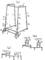
- the mobility aid illustrated in Figures 1 to 5 comprises a four-legged tubular metal (for example aluminium) walking frame that is generally U-shaped in plan, being open at the rear to permit a user to enter and stand within the frame.
- the frame thus comprises four legs 1, the upper ends of which are connected by means of a U-shaped tubular member 2 secured thereto, by means of suitable saddle washers and set bolts, the lateral parts of member 2 each having a padded armrest 2 for engagement by the forearms of the user when standing within the frame.
- the lower ends of the legs 1 are similarly connected by means of respective tubular side members 3, one at each side of the frame, and a tubular front cross member 4.
- Each leg 1 is adjustable in length, comprising relatively slidable upper, inner and lower, outer circular section tubular members, 1 a and 1 b, respectively, that can be secured together in a plurality of different relative positions by means of a fixing pin 5 passed through appropriate aligned holes 6 in the members.
- the height of the front of the frame is 33 inches (840 mm) and the height of the rear of the frame is 30 inches (750 mm), the front legs being forwardly inclined at an angle of about 10° to vertical, while the rear legs are similarly rearwardly inclined at an angle of about 4° to vertical.
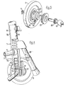
- each front leg further comprises a tubular die-cast member 7 having an upper circular section portion 7a a that receives the associated tubular member 1 b and a lower square section portion 7b.
- An axle 8 carrying a rubber tyred ground-engaging wheel 9 at each end thereof spans the front of the frame, passing through a series of four longitudinal slots 10, one in each lateral face of the lower portion 7b of members 7, the wheels 9 being situated outboard of the associated front leg and being retained on the axle by means of respective circlips 11.
- the axle 8 is supported within each front leg member 7 in a bearing sleeve 12, via appropriate spherical self-aligning inserts 13, slidable within the member 7 and urged downwardly of the latter by a spring 14 housed within the member 7 above the bearing sleeve 12.
- the upper end of the spring 14 is engaged by a slidable plunger 15 that can be selectively retained in one of four positions along the length of the leg by engagement of an adjusting rod 16, fixed to the plunger and having a terminal knob 17, in an appropriate position in notched slot 18 at the front of member 7, to permit adjustment of the spring load and hence adjustment of the download applied to the axle 8 to suit the physique and weight of the intended user.
- Each member 7 is fitted with a toothed rack 19 adjacent to the outer slot 10, the rack 19 cooperating with respective pinions 20 on the axle 8 so that the latter is both held in a constant attitude with respect to the frame while moving up and down relatively to the front legs, between the lowest position as shown in Figure 4 and the highest position as shown in Figure 2 and caused to rotate while so moving, rotating in a forward direction on upward movement, and vice versa.
- the freewheel mechanism 21 comprises a steel ratchet insert 22 keyed to axle 8 and located within the wheel hub by means of a threaded retainer ring 23 such that steel balls 24 are urged into engagement with an appropriately ramped cylindrical surface 25 of the hub by means of associated springs 26 located in radial bores 27 in the ratchet insert 22.
- the arrangement is thus such that the wheels 9 are freely rotatable in a forward direction on the axle 8 and are caused to rotate in this sense by forward rotation of the axle caused by upward movement thereof relative to the front legs 1.
- the front legs of the frame have rubber capped stabilizer struts 28 projecting forwardly and downwardly to engage the ground ahead of the wheel contact patches under circumstances in which forwards toppling of the aid might occur.
- the struts are of adjustable length, being of telescopic tubular construction, and may thus be used to regulate the permitted upward movement of the wheels relative to the front legs and hence to regulate the forward movement of the frame caused by such movement of the wheels.
- the ground-engaging wheels 9 are 5 inches (127 mm) in diameter, and the axes thereof are permitted to move a total of about 1 t inches (41 mm) relatively to the front legs, the rack and pinion gear ratio giving about one half revolution of the axle for a full distance movement of the wheel axes: for a full downwards movement of the front of the frame, the arrangement thus produces a forward movement of about 8 inches (203 mm).
- the freewheel mechanisms permit the frame to be moved forward continuously while nevertheless providing some support for the user, and may thus be used to encourage and teach the user to walk naturally and smoothly.
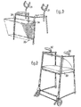
- the frame of Figure 1 may be modified by replacing the padded armrests 2 with arm crutches 29, this modified embodiment being particularly suitable for use by, for example, one-legged users.
- the frame may alternatively be modified by the addition of arm crutches 30 of the configuration shown in Figure 7, or by the addition of arm supports 31 as shown in Figure 8, or by the addition of hand grips 32 as shown in Figure 9.
- Figure 8 is also modified by the addition of a basket 33 removably secured to appropriate fixing hooks 34 on the front legs 1.
- Figure 9 is fitted with a hinged seat member 35 that may be moved from a stowed, vertical position, shown in dot dash lines in the Figure, to a horizontal position of use as shown in full lines to convert the aid into a chair.
Landscapes
- Health & Medical Sciences (AREA)
- Epidemiology (AREA)
- Pain & Pain Management (AREA)
- Physical Education & Sports Medicine (AREA)
- Rehabilitation Therapy (AREA)
- Life Sciences & Earth Sciences (AREA)
- Animal Behavior & Ethology (AREA)
- General Health & Medical Sciences (AREA)
- Public Health (AREA)
- Veterinary Medicine (AREA)
- Rehabilitation Tools (AREA)
- Insulating Bodies (AREA)
- Medicines Containing Plant Substances (AREA)
Claims (10)
Priority Applications (1)
| Application Number | Priority Date | Filing Date | Title |
|---|---|---|---|
| AT79301255T ATE342T1 (de) | 1978-07-05 | 1979-06-28 | Gehhilfe. |
Applications Claiming Priority (2)
| Application Number | Priority Date | Filing Date | Title |
|---|---|---|---|
| GB2896778 | 1978-07-05 | ||
| GB7828967 | 1978-07-05 |
Publications (2)
| Publication Number | Publication Date |
|---|---|
| EP0007708A1 EP0007708A1 (de) | 1980-02-06 |
| EP0007708B1 true EP0007708B1 (de) | 1981-11-04 |
Family
ID=10498282
Family Applications (1)
| Application Number | Title | Priority Date | Filing Date |
|---|---|---|---|
| EP79301255A Expired EP0007708B1 (de) | 1978-07-05 | 1979-06-28 | Gehhilfe |
Country Status (4)
| Country | Link |
|---|---|
| US (1) | US4251105A (de) |
| EP (1) | EP0007708B1 (de) |
| AT (1) | ATE342T1 (de) |
| DE (1) | DE2961230D1 (de) |
Families Citing this family (65)
| Publication number | Priority date | Publication date | Assignee | Title |
|---|---|---|---|---|
| US4387891A (en) * | 1980-12-02 | 1983-06-14 | Knochel E Stanley | Walker |
| US4510956A (en) * | 1983-08-15 | 1985-04-16 | Lorraine King | Walking aid, particularly for handicapped persons |
| GB2154149A (en) * | 1983-11-08 | 1985-09-04 | Uniscan Ltd | A collapsible walking frame |
| SE448936B (sv) * | 1984-04-27 | 1987-03-30 | Hilvar Svensk | Anordning for att underletta forflyttning av en stol |
| US4700730A (en) * | 1986-01-02 | 1987-10-20 | Regents Of The University Of Minnesota | Walker for a small child |
| US4748994A (en) * | 1986-01-17 | 1988-06-07 | Guardian Products, Inc. | Reversible walker device |
| US4765355A (en) * | 1986-09-26 | 1988-08-23 | Kent Charles C | Wheeled walking device |
| US4800910A (en) * | 1987-02-24 | 1989-01-31 | The Kendall Company | Walker |
| US4907794A (en) * | 1987-12-24 | 1990-03-13 | Guardian Products, Inc. | Foldable rolling walker |
| US4941496A (en) * | 1989-03-23 | 1990-07-17 | Berning Louis G | Walker with pivoting wheel |
| US6374436B1 (en) | 1994-01-25 | 2002-04-23 | Hill-Rom Services, Inc. | Hospital bed |
| US5337845A (en) * | 1990-05-16 | 1994-08-16 | Hill-Rom Company, Inc. | Ventilator, care cart and motorized transport each capable of nesting within and docking with a hospital bed base |
| CA2022180C (en) * | 1990-07-27 | 1995-06-06 | Amy E. Lowen | Walking aid device |
| US5112044A (en) * | 1990-10-22 | 1992-05-12 | Dubats Barbara A | Perambulating therapeutic support |
| US5133377A (en) * | 1990-12-05 | 1992-07-28 | Truxillo Peter L | Invalid walker |
| US5378215A (en) * | 1993-05-14 | 1995-01-03 | Harkins; Robert L. | Rehabilitation apparatus for ambulatory patients |
| US5347666A (en) * | 1994-02-04 | 1994-09-20 | Kippes Arlin J | Transfer aid |
| US5509152A (en) * | 1994-02-04 | 1996-04-23 | Kippes; Arlin J. | Transfer aid |
| US5853015A (en) * | 1994-12-07 | 1998-12-29 | Evans; Allan B. | Lightweight easily transportable personal lifting devices |
| NL9500423A (nl) * | 1995-03-03 | 1996-10-01 | Premis Med Bv | Loopwagen. |
| US5794639A (en) * | 1995-10-31 | 1998-08-18 | Einbinder; Eli | Adjustably controllable walker |
| US5579793A (en) * | 1995-11-15 | 1996-12-03 | Rubbermaid Health Care Products, Inc. | Foldable walker |
| US5819772A (en) * | 1996-07-15 | 1998-10-13 | Pi; Ching-Tien | Walker for disabled persons |
| GB9702250D0 (en) * | 1997-02-04 | 1997-03-26 | Flounders Michael | Walking frame |
| USD420945S (en) * | 1998-11-03 | 2000-02-22 | Rubbermaid Commercial Products Llc | Walker wheel |
| WO2001032123A1 (en) * | 1999-11-02 | 2001-05-10 | Sunrise Medical Hhg Inc. | Oxygen bottle holder for walker |
| US6464620B1 (en) * | 1999-11-17 | 2002-10-15 | Dirk Hettrich | Training apparatus for walking |
| US7226396B2 (en) * | 2001-01-25 | 2007-06-05 | Balance Gym Llc | Rehabilitation and fitness trainer apparatus |
| SE523203C2 (sv) * | 2001-03-09 | 2004-03-30 | Margana Ag | Anordning för att underlätta körning med rollator och rollator försedd med sådan anordning |
| US20040020525A1 (en) * | 2002-08-02 | 2004-02-05 | Harry Lev | Combination crutch-walker |
| JP4139192B2 (ja) * | 2002-11-19 | 2008-08-27 | 中井 律子 | 食品の予備加熱調理方法 |
| US7021324B1 (en) | 2003-09-03 | 2006-04-04 | Clay Charles L | Walker with cane holder and non-catch castors |
| US7926834B2 (en) * | 2003-10-07 | 2011-04-19 | AMG Medical, USA | Mobile support assembly |
| US7837208B2 (en) * | 2003-10-07 | 2010-11-23 | Phillip Minyard Willis | Mobile support assembly |
| US7073801B2 (en) * | 2003-10-07 | 2006-07-11 | Access Product Marketing, Llc | Foldable mobility support device |
| US9173802B2 (en) | 2003-10-07 | 2015-11-03 | Amg Medical, Usa. | Mobile support assembly |
| US7540527B2 (en) * | 2003-10-07 | 2009-06-02 | Phillip Minyard Willis | Mobile support assembly |
| US20050139246A1 (en) * | 2003-12-08 | 2005-06-30 | Davidson James J.Jr. | Support Arm |
| US20050156395A1 (en) * | 2004-01-20 | 2005-07-21 | Bohn David L. | Rolling walker with arm rest platforms |
| US7363931B2 (en) * | 2004-11-05 | 2008-04-29 | Craig Weaver | Walker with lifting arms |
| US8166987B2 (en) * | 2004-11-05 | 2012-05-01 | WeCare Products, Inc. USA | Systems and methods for assisting a seated person to a standing position |
| CA2517117A1 (en) * | 2005-05-13 | 2006-11-13 | Philip M. Willis | Walking cane assembly |
| DE102005028299A1 (de) * | 2005-06-18 | 2006-12-21 | Hensel, Renate | Gehhilfe |
| US7451992B2 (en) * | 2006-01-31 | 2008-11-18 | Phillip Minyard Willis | Mobile support assembly |
| US7743779B2 (en) * | 2007-01-19 | 2010-06-29 | Gee Sr Larry Ellis | Crutch stroller |
| US9375380B2 (en) * | 2007-05-11 | 2016-06-28 | Rowanwood Ip Inc. | Mobility assistance device |
| US7445217B1 (en) * | 2007-07-19 | 2008-11-04 | Donald J Price | Walk aid |
| US20090152826A1 (en) * | 2007-12-18 | 2009-06-18 | Jose Freitas Silva | Cargo cart with hitch for wheeled mobility device |
| US7677259B1 (en) | 2008-05-16 | 2010-03-16 | Arbuckle Jetta E | Crutch walker and associated use therefor |
| US7779850B2 (en) * | 2008-06-05 | 2010-08-24 | Pamela Caldwell | Anti-tipping device for walkers |
| US8439376B2 (en) * | 2008-07-08 | 2013-05-14 | Amg Medical, Usa. | Mobile support assembly |
| US8020881B2 (en) * | 2008-11-11 | 2011-09-20 | Earl Stump | Mobility assistance apparatus |
| FR2955251B1 (fr) * | 2010-01-18 | 2013-06-28 | Hill Rom Sas | Lit medicalise equipe d'un dispositif d'aide a la mobilite d'un patient. |
| FR2954693B1 (fr) * | 2009-12-30 | 2012-11-30 | Maurice Cazes | Deambulateur antichute. |
| FR2970171B1 (fr) * | 2011-01-11 | 2013-06-21 | Maurice Cazes | Deambulateur universel |
| GB201212432D0 (en) * | 2012-07-12 | 2012-08-29 | Nottingham Rehab Ltd | Walking frame and foot therefor |
| US8540256B1 (en) * | 2012-10-30 | 2013-09-24 | Thomas Grady Simpson | Up-right walker for supporting a patient with up-right posture |
| US8936033B2 (en) * | 2013-03-15 | 2015-01-20 | Arvin Jay D. Velarde | Walking apparatus |
| US9478951B2 (en) | 2014-12-30 | 2016-10-25 | Schneider Electric USA, Inc. | Method for treating internal arcs |
| US20190175429A1 (en) * | 2015-03-19 | 2019-06-13 | Lucent Medical Systems, Inc. | Support frame with optional anti-skid/anti-tip structure |
| EP3284616B1 (de) * | 2016-08-16 | 2022-06-22 | Hill-Rom Services, Inc. | Betätigungsanordnung und verfahren zur herstellung |
| CN110248572A (zh) | 2016-11-16 | 2019-09-17 | 想往设计有限公司 | 便携式框架 |
| US10583065B1 (en) * | 2019-01-16 | 2020-03-10 | Melanie Mejia | Posture-correcting walker |
| US11510842B2 (en) * | 2019-07-17 | 2022-11-29 | Delphine HC Innovations, LLC | Ergonomic ambulation assist device |
| US20220040029A1 (en) * | 2020-08-10 | 2022-02-10 | Avery Jordan ALPERIN | Anti-tipping apparatus for walkers |
Family Cites Families (11)
| Publication number | Priority date | Publication date | Assignee | Title |
|---|---|---|---|---|
| DE401711C (de) * | 1920-07-28 | 1924-09-09 | Heinrich Westphal | Stelze mit durch Spreizung erfolgendem Vortrieb |
| US2621707A (en) * | 1944-06-24 | 1952-12-16 | Ames Butler | Walkabout |
| US2690788A (en) * | 1945-01-24 | 1954-10-05 | Ames Butler | Portable support |
| US2792874A (en) * | 1953-04-17 | 1957-05-21 | Olle M Sundberg | Orthopedic walker |
| US2745465A (en) * | 1954-04-13 | 1956-05-15 | Walk A Lator Mfg Co Inc | Invalid walker |
| US3195550A (en) * | 1962-09-06 | 1965-07-20 | John G Ingalls | Walking devices |
| US3237940A (en) * | 1963-10-22 | 1966-03-01 | Auline S Johnson | Safety brake casters for walking aid |
| GB1096547A (en) * | 1965-11-13 | 1967-12-29 | Cyril Hornby | Improvements in or relating to walking-aids |
| GB1342397A (en) * | 1971-05-21 | 1974-01-03 | Drove Precision Eng Co Ltd | Carrier with rolling elements |
| GB1373593A (en) * | 1973-03-20 | 1974-11-13 | Thrift P A | Glide for use on articles of furniture or the like |
| US4046374A (en) * | 1973-05-14 | 1977-09-06 | Breyley Thomas E | Walking aid |
-
1979
- 1979-06-28 EP EP79301255A patent/EP0007708B1/de not_active Expired
- 1979-06-28 DE DE7979301255T patent/DE2961230D1/de not_active Expired
- 1979-06-28 AT AT79301255T patent/ATE342T1/de not_active IP Right Cessation
- 1979-07-03 US US06/054,424 patent/US4251105A/en not_active Expired - Lifetime
Also Published As
| Publication number | Publication date |
|---|---|
| US4251105A (en) | 1981-02-17 |
| DE2961230D1 (en) | 1982-01-14 |
| ATE342T1 (de) | 1981-11-15 |
| EP0007708A1 (de) | 1980-02-06 |
Similar Documents
| Publication | Publication Date | Title |
|---|---|---|
| EP0007708B1 (de) | Gehhilfe | |
| US5964473A (en) | Wheelchair for transporting or assisting the displacement of at least one user, particularly for handicapped person | |
| CA2406916C (en) | Walker chair | |
| EP0009260B1 (de) | Vorrichtung zur Erleichterung des Gehens für einen partiell Behinderten | |
| US9016297B2 (en) | Wheeled support cane | |
| US10391018B1 (en) | Walk again walker | |
| US5785070A (en) | Dual handled walking and uprisal assist device | |
| US4510956A (en) | Walking aid, particularly for handicapped persons | |
| US4800910A (en) | Walker | |
| CA2022180C (en) | Walking aid device | |
| US10772788B2 (en) | Rollator | |
| US7111856B1 (en) | Bipedal motion assisting method and apparatus | |
| US4226413A (en) | Wheel mounted walker with foot pedal brake | |
| US5794639A (en) | Adjustably controllable walker | |
| US4907794A (en) | Foldable rolling walker | |
| US7494138B2 (en) | Bipedal motion assisting method and apparatus | |
| US5692762A (en) | Walker with glide assembly | |
| US3455313A (en) | Walker for ascending and descending ramps and staircases | |
| US20170209319A1 (en) | Elevating walker chair | |
| US5538268A (en) | Foldable walking stabilizer device for physically disabled persons | |
| US5636651A (en) | Adjustably controllable walker | |
| US6003532A (en) | Wheeled triple-leg walker | |
| US5839740A (en) | Cart for injured persons | |
| US9566207B1 (en) | Hi-rise walker | |
| US5605169A (en) | Collapsible walker with a retractable seat |
Legal Events
| Date | Code | Title | Description |
|---|---|---|---|
| PUAI | Public reference made under article 153(3) epc to a published international application that has entered the european phase |
Free format text: ORIGINAL CODE: 0009012 |
|
| AK | Designated contracting states |
Designated state(s): AT BE CH DE FR GB IT LU NL SE |
|
| 17P | Request for examination filed | ||
| GRAA | (expected) grant |
Free format text: ORIGINAL CODE: 0009210 |
|
| AK | Designated contracting states |
Designated state(s): AT BE CH DE FR GB IT LU NL SE |
|
| PG25 | Lapsed in a contracting state [announced via postgrant information from national office to epo] |
Ref country code: NL Effective date: 19811104 Ref country code: IT Free format text: LAPSE BECAUSE OF FAILURE TO SUBMIT A TRANSLATION OF THE DESCRIPTION OR TO PAY THE FEE WITHIN THE PRESCRIBED TIME-LIMIT;WARNING: LAPSES OF ITALIAN PATENTS WITH EFFECTIVE DATE BEFORE 2007 MAY HAVE OCCURRED AT ANY TIME BEFORE 2007. THE CORRECT EFFECTIVE DATE MAY BE DIFFERENT FROM THE ONE RECORDED. Effective date: 19811104 |
|
| REF | Corresponds to: |
Ref document number: 342 Country of ref document: AT Date of ref document: 19811115 Kind code of ref document: T |
|
| PG25 | Lapsed in a contracting state [announced via postgrant information from national office to epo] |
Ref country code: AT Effective date: 19820105 |
|
| REF | Corresponds to: |
Ref document number: 2961230 Country of ref document: DE Date of ref document: 19820114 |
|
| NLV1 | Nl: lapsed or annulled due to failure to fulfill the requirements of art. 29p and 29m of the patents act | ||
| PG25 | Lapsed in a contracting state [announced via postgrant information from national office to epo] |
Ref country code: LU Free format text: LAPSE BECAUSE OF NON-PAYMENT OF DUE FEES Effective date: 19820630 |
|
| PG25 | Lapsed in a contracting state [announced via postgrant information from national office to epo] |
Ref country code: SE Effective date: 19821104 |
|
| PGFP | Annual fee paid to national office [announced via postgrant information from national office to epo] |
Ref country code: LU Payment date: 19830704 Year of fee payment: 5 |
|
| PGFP | Annual fee paid to national office [announced via postgrant information from national office to epo] |
Ref country code: FR Payment date: 19840621 Year of fee payment: 6 |
|
| PGFP | Annual fee paid to national office [announced via postgrant information from national office to epo] |
Ref country code: CH Payment date: 19840626 Year of fee payment: 6 |
|
| PGFP | Annual fee paid to national office [announced via postgrant information from national office to epo] |
Ref country code: DE Payment date: 19840628 Year of fee payment: 6 |
|
| PGFP | Annual fee paid to national office [announced via postgrant information from national office to epo] |
Ref country code: BE Payment date: 19840930 Year of fee payment: 6 |
|
| PG25 | Lapsed in a contracting state [announced via postgrant information from national office to epo] |
Ref country code: CH Effective date: 19870630 |
|
| BERE | Be: lapsed |
Owner name: BARKER ALFRED WALTER Effective date: 19870630 |
|
| PG25 | Lapsed in a contracting state [announced via postgrant information from national office to epo] |
Ref country code: FR Free format text: LAPSE BECAUSE OF NON-PAYMENT OF DUE FEES Effective date: 19880226 |
|
| REG | Reference to a national code |
Ref country code: CH Ref legal event code: PL |
|
| PG25 | Lapsed in a contracting state [announced via postgrant information from national office to epo] |
Ref country code: DE Effective date: 19880301 |
|
| GBPC | Gb: european patent ceased through non-payment of renewal fee | ||
| REG | Reference to a national code |
Ref country code: FR Ref legal event code: ST |
|
| PG25 | Lapsed in a contracting state [announced via postgrant information from national office to epo] |
Ref country code: GB Effective date: 19881118 |
|
| PG25 | Lapsed in a contracting state [announced via postgrant information from national office to epo] |
Ref country code: BE Effective date: 19890630 |
|
| PLBE | No opposition filed within time limit |
Free format text: ORIGINAL CODE: 0009261 |
|
| STAA | Information on the status of an ep patent application or granted ep patent |
Free format text: STATUS: NO OPPOSITION FILED WITHIN TIME LIMIT |