EP0001565A1 - Electric circuit for a directly driven rotary cutting device - Google Patents
Electric circuit for a directly driven rotary cutting device Download PDFInfo
- Publication number
- EP0001565A1 EP0001565A1 EP78100971A EP78100971A EP0001565A1 EP 0001565 A1 EP0001565 A1 EP 0001565A1 EP 78100971 A EP78100971 A EP 78100971A EP 78100971 A EP78100971 A EP 78100971A EP 0001565 A1 EP0001565 A1 EP 0001565A1
- Authority
- EP
- European Patent Office
- Prior art keywords
- regulator
- acceleration
- controller
- speed
- path
- Prior art date
- Legal status (The legal status is an assumption and is not a legal conclusion. Google has not performed a legal analysis and makes no representation as to the accuracy of the status listed.)
- Granted
Links
Images

Classifications
-
- B—PERFORMING OPERATIONS; TRANSPORTING
- B23—MACHINE TOOLS; METAL-WORKING NOT OTHERWISE PROVIDED FOR
- B23D—PLANING; SLOTTING; SHEARING; BROACHING; SAWING; FILING; SCRAPING; LIKE OPERATIONS FOR WORKING METAL BY REMOVING MATERIAL, NOT OTHERWISE PROVIDED FOR
- B23D36/00—Control arrangements specially adapted for machines for shearing or similar cutting, or for sawing, stock which the latter is travelling otherwise than in the direction of the cut
- B23D36/0008—Control arrangements specially adapted for machines for shearing or similar cutting, or for sawing, stock which the latter is travelling otherwise than in the direction of the cut for machines with only one cutting, sawing, or shearing devices
- B23D36/0033—Control arrangements specially adapted for machines for shearing or similar cutting, or for sawing, stock which the latter is travelling otherwise than in the direction of the cut for machines with only one cutting, sawing, or shearing devices for obtaining pieces of a predetermined length
- B23D36/0041—Control arrangements specially adapted for machines for shearing or similar cutting, or for sawing, stock which the latter is travelling otherwise than in the direction of the cut for machines with only one cutting, sawing, or shearing devices for obtaining pieces of a predetermined length the tool moving continuously
-
- B—PERFORMING OPERATIONS; TRANSPORTING
- B26—HAND CUTTING TOOLS; CUTTING; SEVERING
- B26D—CUTTING; DETAILS COMMON TO MACHINES FOR PERFORATING, PUNCHING, CUTTING-OUT, STAMPING-OUT OR SEVERING
- B26D5/00—Arrangements for operating and controlling machines or devices for cutting, cutting-out, stamping-out, punching, perforating, or severing by means other than cutting
- B26D5/38—Arrangements for operating and controlling machines or devices for cutting, cutting-out, stamping-out, punching, perforating, or severing by means other than cutting with means operable by the moving work to initiate the cutting action
- B26D5/40—Arrangements for operating and controlling machines or devices for cutting, cutting-out, stamping-out, punching, perforating, or severing by means other than cutting with means operable by the moving work to initiate the cutting action including a metering device
Definitions
- the invention relates to a circuit arrangement for the direct electrical drive of a rotating cutting device for the format-appropriate cutting of a material web, in particular a flying shear or a synchronous cross cutter, in which a position controller, a speed controller, an acceleration controller and a subordinate current controller are provided.
- the invention has for its object to provide a circuit arrangement of the type mentioned for a time-optimal and path-optimal movement of a rotating separation device.
- this object is achieved in that a computing device is provided, which from predetermined settings and continuously measure the command values for the position controller and the speed controller from measured values for the path.
- Acceleration controller determined in accordance with the equation of motion of the racing device, the output signal of the position controller being applied to the speed controller as a correction variable and the output signal of the speed controller being connected to the acceleration controller as a correcting variable.
- the control arrangement according to the invention works optimally in terms of time because, if necessary, the full acceleration capacity of the drive can be used. Likewise, depending on the machine data and the production speed, the energy required for the acceleration processes and the braking processes of the separating device can also be limited to the extent required for the cutting sequence.
- the control arrangement according to the invention also works optimally because the path and the guide variable for the path covered by the separating device are coupled via the Rochenei device and any deviation from the optimal path of the cutting tool leads to correction via the speed controller.
- the computing device can also limit the web speed and the start-up process depending on form errors. Finally, the computing device can also capture Simplybauma and before 'reaching the target quantity display a message, or automatically stop the production ..
- FIG. 1 shows the structural circuit diagram of a circuit arrangement according to the invention for a synchronous quench.
- a web of material 20 is pulled from an unwind roll and through a pair of knife rollers 18, 19 with knives 23, 24 passed through.
- the knife rollers 18 and 19 are driven in opposite directions by an electrical machine 13.
- the knives 23 and 24 preferably have a small angle of attack with respect to the transverse direction of the material web 20.
- the direct drive for the knife rollers 18 and 19 comprises an electrical machine 13, which is fed via a converter 11 from a three-phase network 12.
- a counter-parallel circuit with two fully controlled three-phase bridges is particularly suitable as the converter.
- the converter 11 is controlled by a control set 10 with ignition pulses, the ignition angle of which is determined by the output voltage of a current regulator 9.
- the current regulator 9 is preceded by a comparator 8, which is acted upon by the output signal I * of an acceleration regulator 7 as a reference variable and by the control variable I of the current control circuit detected by a current measuring transducer 14.
- the comparator 8 forms the control difference for the current controller 9.
- the circuit arrangement shown contains an acceleration controller 7 connected upstream of the current controller 9, a speed controller 5 and a position controller 3, each of which has comparison members connected upstream.
- a digital speed sensor 15 is provided which works according to the principle of an angular step encoder and which consists of a disk which is fixedly connected to the shaft of the drive machine 13 and has a large number of magnetically, electrically or optically recognizable elements evenly distributed over the circumference, a probe scanning these elements and a pulse shaper stage.
- the speed of the drive machine 13 detected by the digital speed sensor 15 is added up in a digital integrator 17, the output signal of which represents a measure of the distance covered by the knives 23 and 24 of the knife rollers 18 and 19 with each revolution.
- the output signal s of the integrator 17 is fed to the comparator 2 in the input of the position controller 3 as a controlled variable for the position control.
- the command variable s * for the position controller 3 is output by a computing device 1.
- the computing device 1 also determines the reference variable n * for the speed controller 5 and the command variable b * for the acceleration controller 7.
- the command variable n * for the speed controller 5 is fed to its comparator 4 together with the output signal n of the position controller 3 as a correction signal and the controlled variable n of the speed control loop.
- the controlled variable n of the speed control loop is the speed of the drive machine 13 detected by the digital speed sensor 15, which is converted into an analog voltage by a digital-analog converter 28, provided the speed controller 5 is designed as an analog controller.
- the reference variable b * for the acceleration controller 7 is fed to its comparator 6 together with the output signal b of the speed controller 5 as a correction signal and the control variable b of the acceleration control loop.
- the controlled variable b of the acceleration control loop is measured as a differential quotient of the speed n of the drive machine 13.
- the speed detected by the digital speed sensor 15, after its implementation in the digital-to-analog converter 28, is guided via a differential generator 16, the output signal b of which represents the actual value of the acceleration of the drive machine 13.
- the output signal I * of the acceleration controller 7 is fed to the comparison element 8 as a reference variable for the current control loop.
- the computing device 1 determines the reference variable s * for the position controller 3, the reference variable n * for the speed controller 5 and the reference variable b * for the acceleration controller 7 from predetermined setting values and from measured values for the path.
- a digital displacement sensor 22 is provided, which is driven, for example, by a friction wheel from the material web 20 running in the direction of the arrow.
- the digital displacement sensor 22, for example likewise has a disk with a large number of magnetically, electrically or optically recognizable elements distributed uniformly over the circumference, which are scanned by a probe, which is followed by a pulse shaper stage.
- a setting value for the format into which the material web 20 is to be divided is specified on a setting device 25.
- Mechanical machine data in particular the path speed and the moment of inertia of the entire arrangement, are specified on a further setting device 26.
- Another setting device 27 sets a limit value for the reference variable b * for the acceleration, which is preferably selected below the maximum acceleration capacity of the drive so that the acceleration controller 7 can intervene in both directions.
- equation (1) eliminates the initial value s o of the path of the cutting edge of the cutting tool.
- equation (1) the path s of the cutting edge of the cutting tool appears as a function of time t.
- the computing device used in the control system according to the invention is intended to calculate the knife path sin as a function of the measured path path x. The equation therefore becomes the substitution of time t (2) inserted in equation (1):
- x means: path
- w path speed
- a graphic representation of the path s of the cutting edge of the cutting tool as a function of the path path x shows a different course of the curve depending on whether a synchronous format, a sub-synchronous format or an oversynchronous format is to be cut.
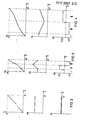
- FIG. 2 shows the path s of the cutting edge of the cutting tool, the speed n of the knife roller and the acceleration b of the separating device in each case as a function of the path x.
- Synchronous format means that the path s1 described by the rotating cutting edge of the cutting tool on a cylinder circumference corresponds to the format x1 to be cut.
- the path function is a straight line with an inclination angle of 45 0 .
- the knife cylinder rotates at a uniform speed.
- the speed function is a horizontal straight line.
- the knife cylinder is neither accelerated nor braked.
- the acceleration is zero.
- FIG. 3 shows the path s of the cutting edge of the cutting tool, the speed n of the knife cylinder and the acceleration b in each case as a function of the path path x.
- Sub-synchronous format means that the path x2 corresponding to the format is smaller than the path s1 described by the rotating cutting edge of the cutting tool on a cylinder circumference. If a sub-synchronous format is to be cut, the speed of the cutting edge of the cutting tool must be equal to the path speed during the cut in order to ensure a smooth cut. Then the knife cylinder accelerates so that the cutting tool overtakes the web. Finally, the knife cylinder is braked back to the web speed.
- the path function is in the cutting phase I a straight line with a slope angle of 45 0, in the acceleration phase II a rising parabola an acceleration parabola and in the braking phase III flattening a parabola of a brake parabola.
- the speed function n shows a horizontal straight line in the cutting phase I, a rising straight line in the acceleration phase II and a falling line in the braking phase III.
- the acceleration function b shows the acceleration value zero in the cutting phase I, a positive acceleration value b2 in the acceleration phase and a deceleration value -b2 of the same size in braking phase III.
- FIG. 4 shows the course of the path s of the cutting edge of the cutting tool, the speed n of the knife cylinder and the acceleration b as a function of the path path x for an oversynchronous format.
- a super-synchronous format means that the path x3 corresponding to the format is larger than the path 1 covered by the rotating cutting edge of the cutting tool on a cylinder circumference Adjust web speed to ensure a smooth cut. Then the knife cylinder is braked and then accelerated again.
- the path function s shows in section phase I a straight line with an inclination angle of 45 °, in the subsequent braking phase III a flattening parabola load of a brake parabola and in acceleration phase II an increasing parabola load of an acceleration parabola.
- the speed function inclines a horizontal straight line in cutting phase I, a falling straight line in brams phase III and an ascending straight line in acceleration phase II.
- the acceleration function b shows the acceleration value zero in the cutting phase I, a negative acceleration value -b3 in the braking phase III and a positive acceleration value b3 in the acceleration phase II.
- the initial speed v of the cutting edge of the cutting tool is equal to the path speed w.
- FIGS. 3 and 4 further show that the parabolic load of the brake parabola is only rotated by 180 ° with respect to the parabola load of the acceleration parabola, the same absolute acceleration values and deceleration values being required. This requirement can be easily met with direct electric drives.
- equation (1a) can be rewritten to equation (1b):
- the functional curves shown in FIGS. 2, 3, 4 are the basis of the calculations to be carried out by the computing device 1 to determine the reference variable s * for the position controller, the reference variable n * for the speed controller and the reference variable b * for the acceleration controller.
- the computing device 1 can determine these reference variables, for example, using function transmitters which emulate the functions shown.
- parabolic interpolation can also be carried out, as described, for example, in Siemens magazine 44, 1970, supplement "Numerical controls", pages 58-62.
- An associated reference variable for the position controller, the speed controller and the acceleration controller can be stored for each travel element detected by the digital travel sensor 22. It is also possible to store various tables for different production programs with different cutting tools and different web speeds.
- the computing device may take over the function of the digital integrator 17, the position controller 3 and the upstream comparison element 2. This does not change the basic functioning of such a circuit arrangement with a position controller included in the computer.
Landscapes
- Engineering & Computer Science (AREA)
- Mechanical Engineering (AREA)
- Life Sciences & Earth Sciences (AREA)
- Forests & Forestry (AREA)
- Numerical Control (AREA)
Abstract
Description
Die Erfindung bezieht sich auf eine Schaltungsanordnung für den elektrischen Direktantrieb einer rotierenden Trennvorrichtung zum formatgerechten Zerteilen einer Materialbahn, insbesondere einer fliegenden Schere oder eines Gleichlaufquerschneiders, bei der ein Lageregler, ein Drehzahlregler, ein Beschleunigungsregler und ein unterlagerter Stromregler vorgesehen sind.The invention relates to a circuit arrangement for the direct electrical drive of a rotating cutting device for the format-appropriate cutting of a material web, in particular a flying shear or a synchronous cross cutter, in which a position controller, a speed controller, an acceleration controller and a subordinate current controller are provided.
Eine derartige Schaltungsanordnung ist aus dem Beitrag "Zeitoptimale Scherenregelung" von Prof. W. Leonard im Archiv für Elektrotechnik 59 (1976) Seite 61 - 67 bekannt. Bei der dort beschriebenen zeitoptimalen Lageregelung mit gleichförmig bewegtem Zielpunkt ist ein nichtlinearer Lageregler vorgesehen, dessen Verstärkung in Abhängigkeit von einer Bremskurve verändert wird. Dies bringt eine unerwünschte Unsicherheit bei der Dimensionierung der Regelung mit sich. Bei der bekannten Scherenregelung ist darüberhinaus eine Begrenzung für den Beschleunigungssollwert vorgesehen, die sich bei Laststößen störend auswirkt.Such a circuit arrangement is known from the article "Time-optimal scissor control" by Prof. W. Leonard in the Archive for Electrical Engineering 59 (1976) pages 61-67. In the time-optimal position control described there with a uniformly moving target point, a non-linear position controller is provided, the gain of which is changed as a function of a braking curve. This brings with it an undesirable uncertainty when dimensioning the control. In the known scissor control system, a limitation is also provided for the acceleration setpoint, which has a disruptive effect in the event of load surges.
Der Erfindung liegt die Aufgabe zugrunde, eine Schaltungsanordnung der eingangs genannten Art für eine zeitoptimal und wegoptimal verlaufende Bewegung einer rotierenden Trennvorrichtung zu schaffen.The invention has for its object to provide a circuit arrangement of the type mentioned for a time-optimal and path-optimal movement of a rotating separation device.
Erfindungsgemäß wird diese Aufgabe dadurch gelöst, daß eine Recheneinrichtung vorgesehen ist, die aus vorgegebenen Einstellwerten und aus Meßwerten für den Bahnweg fortlaufend die Führungsgrößen für den Lageregler, den Drehzahlregler uni der. Beschleunigungsregler nach Maßgabe der Bewegungsgleichung der rennvorrichtung ermittelt, wobei das Ausgangssignal des Lagereglers dem Drehzahlregler als Korrekturgröße und das Ausgangssigial des Drehzahlreglers dem Beschleunigungsregler als Korrektergröße aufgeschaltet ist.According to the invention, this object is achieved in that a computing device is provided, which from predetermined settings and continuously measure the command values for the position controller and the speed controller from measured values for the path. Acceleration controller determined in accordance with the equation of motion of the racing device, the output signal of the position controller being applied to the speed controller as a correction variable and the output signal of the speed controller being connected to the acceleration controller as a correcting variable.
Die erfindungsgemäße Regelanordnung arbeitet zeitoptinal, weil bei Bedarf das volle Beschleunigungsvermögen des Antriebs ausgenützt werden kann. Ebenso kann aber auch abhängig vor den Maschinendaten und der Produktionsgeschwindigkeit die fü die Beschleunigungsvorgänge und die Bremsvorgänge der Trennvorrichtung erforderliche Energie auf das für die Schnittfolge erforderliche Maß begrenzt werden. Die erfindungsgemäße Regelanordnung arbeitet auch wegoptimal, weil der Bahnweg und die Führungsgröße für den von der Trennvorrichtung zurückgelegten Weg über die Rocheneia- richtung gekoppelt sind und jede Abweichung vom optimal en Weg des Schneidewerkzeugs zur Korrektur über den Drehzahlregler führt. Die Recheneinrichtung kann außerdem abhängig von Formafehlern die Bahngeschwindigkeit und den Hochfahrvorgang begrenzen. Schließlich kann die Recheneinrichtung auch Stückzahla erfassen und vor'Erreichen der Sollstückzahl eine Meldung ausgeben oder selbsttätig die Produktion beenden..The control arrangement according to the invention works optimally in terms of time because, if necessary, the full acceleration capacity of the drive can be used. Likewise, depending on the machine data and the production speed, the energy required for the acceleration processes and the braking processes of the separating device can also be limited to the extent required for the cutting sequence. The control arrangement according to the invention also works optimally because the path and the guide variable for the path covered by the separating device are coupled via the Rochenei device and any deviation from the optimal path of the cutting tool leads to correction via the speed controller. The computing device can also limit the web speed and the start-up process depending on form errors. Finally, the computing device can also capture Stückzahla and before 'reaching the target quantity display a message, or automatically stop the production ..
Ein Ausführungsbeispiel der Erfindung ist in der Zechnung dargestellt und wird im folgenden näher beschrieben. E zeigen:
- Figur 1 eine erfindungsgemäße Schaltungsanordnung,
- Figur 2 eine Darstellung des Verlaufs der Regelgröen bei Synchronformat,
- Figur 3 eine Darstellung des Verlaufs der Regelgr3enbei untersynchronem Format,
- Figur 4 eine Darstellung des Verlaufs der Regelgößen bei übersynchronem Format.
- FIG. 1 shows a circuit arrangement according to the invention,
- FIG. 2 shows the course of the control variables in the synchronous format,
- FIG. 3 shows the course of the control variables in the case of a sub-synchronous format,
- FIG. 4 shows the course of the controlled variables in the case of an oversynchronous format.
Figur 1 zeigt das Strukturschaltbild einer ebiundungsgemäßen Schaltungsanordnung für einen Gleichlaufquech neider. Eine Materialbahn 20 wird von einer Abwickelrolle aubgezogen und durch ein Messerwalzenpaar 18, 19 mit Messern 23, 24 hindurchgeführt. Die Messerwalzen 18 und 19 werden von einer elektrischen Maschine 13 gegenläufig angetrieben. Die Messer 23 und 24 weisen vorzugsweise einen kleinen Anstellwinkel gegenüber der Querrichtung der Materialbahn 20 auf.FIG. 1 shows the structural circuit diagram of a circuit arrangement according to the invention for a synchronous quench. A web of
Der Direktantrieb für die Messerwalzen 18 und 19 umfaßt eine elektrische Maschine 13, die über einen Stromrichter 11 aus einem Drehstromnetz 12 gespeist wird. Als Stromrichter ist insbesondere eine Gegenparallelschaltung mit zwei vollgesteuerten Drehstrombrücken geeignet. Der Stromrichter 11 wird von einem Steuersatz 10 mit Zündimpulsen gesteuert, deren Zündwinkel von der Ausgangsspannung eines Stromreglers 9 bestimmt wird. Dem Stromregler 9 ist ein Vergleichsglied 8 vorgeschaltet, das aus dem Ausgangssignal I* eines Beschleunigungsreglers 7 als Führungsgröße und aus der von einem Strommeßwandler 14 erfaßten Regelgröße I des Stromregelkreises beaufschlagt wird. Das Vergleichsglied 8 bildet die Regeldifferenz für den Stromregler 9.The direct drive for the
Weiterhin enthält die dargestellte Schaltungsanordnung einen dem Stromregler 9 vorgeschalteten Beschleunigungsregler 7, einen Drehzahlregler 5 und einen Lageregler 3, denen jeweils Vergleichsglieder vorgeschaltet sind. Zur Erfassung der Drehzahlen der Antriebsmaschine 13 ist beispielsweise ein nach dem Prinzip eines Winkelschrittgebers arbeitender digitaler Drehzahlgeber 15 vorgesehen, der aus einer mit der Welle der Antriebsmaschine 13 fest verbundenen Scheibe mit einer großen Anzahl von am Umfang gleichmäßig verteilten magnetisch, elektrisch oder optisch erkennbaren Elementen, einer diese Elemente abtastenden Sonde und einer Impulsformerstufe besteht. Die von digitalen Drehzahlgeber 15 erfaßte Drehzahl der Antriebsmaschine 13 wird in einem digitalen Integrator 17 aufsummiert, dessen Ausgangssignal ein Maß für den von den Messern 23 bzw. 24 der Messerwalzen 18 bzw. 19 bei jeder Umdrehung zurückgelegten Weg darstellt. Das Ausgangssignal s des Integrators 17 wird dem Vergleichsglied 2 im Eingang des Lagereglers 3 als Regelgröße für die Lageregelung zugeführt. Die Führungsgröße s* für den Lageregler 3 wird von einer Recheneinrichtung 1 ausgegeben. Die Recheneinrichtung 1 ermittelt außerdem die Führungsgröße n* für den Drehzahlregler 5 und die Führungsgröße b* für den Beschleunigungsregler 7. Die Führungsgröße n* für den Drehzahlregler 5 wird seinem Vergleichsglied 4 zusammen mit dem Ausgangssignal n des Lagereglers 3 als Korrektursignal und der Regelgröße n des Drehzahlregelkreises zugeführt. Die Regelgröße n des Drehzahlregelkreises ist die vom digitalen Drehzahlgeber 15 erfaßte Drehzahl der Antriebsmaschine 13, die von einem Digital-Analog-Wandler 28 in eine analoge Spannung umgesetzt wird, sofern der Drehzahlregler 5 als analoger Regler ausgebildet ist.Furthermore, the circuit arrangement shown contains an acceleration controller 7 connected upstream of the
Die Führungsgröße b* für den Beschleunigungsregler 7 wird seinem Vergleichsglied 6 zusammen mit dem Ausgangssignal b des Drehzahlreglers 5 als Korrektursignal und der Regelgröße b des Beschleunigungsregelkreises zugeführt. Die Regelgröße b des Beschleunigungsregelkreises wird meßtechnisch als Differentialquotient der Drehzahl n der Antriebsmaschine 13 erfaßt. Die vom digitalen Drehzahlgeber 15 erfaßte Drehzahl wird nach ihrer Umsetzung im Digital-Analog-Wandler 28 über einen Differentialbildner 16 geführt, dessen Ausgangssignal b den Istwert der Beschleunigung der Antriebsmaschine 13 darstellt. Das Ausgangssignal I* des Beschleunigungsreglers 7 wird dem Vergleichsglied 8 als Führungsgröße für den Stromregelkreis zugeführt.The reference variable b * for the acceleration controller 7 is fed to its comparator 6 together with the output signal b of the
Die Recheneinrichtung 1 ermittelt die Führungsgröße s* für den Lageregler 3, die Führungsgröße n* für den Drehzahlregler 5 und die Führungsgröße b* für den Beschleunigungsregler 7 aus vorgegebenen Einstellwerten und aus Meßwerten für den Bahnweg. Zur Ermittlung des Bahnweges ist ein digitaler Weggeber 22 vorgesehen, der beispielsweise über ein Reibrad von der in Pfeilrichtung ablaufenden Materialbahn 20 angetrieben wird. Der digitale Weggeber 22 weist beispielsweise ebenfalls eine Scheibe mit einer großen Anzahl von am Umfang gleichmäßig verteilten magnetisch, elektrisch oder optisch erkennbaren Elementen auf, die von einer Sonde abgetastet werden, der eine Impulsformerstufe nachgeschaltet ist. An einer Einstellvorrichtung 25 wird ein Einstellwert für das Format vorgegeben, in das die Materialbahn 20 zerteilt werden soll. An einer weiteren Einstellvorrichtung 26 werden mechanische Maschinendaten vorgegeben, insbesondere die Bahngeschwindigkeit und das Trägheitsmoment der gesamten Anordnung. An einer weiteren Einstellvorrichtung 27 wird ein Begrenzungswert für die Führungsgröße b* für die Beschleunigung eingestellt, der vorzugsweise unterhalb des maximalen Beschleunigungsvermögens des Antriebs gewählt wird, damit der Beschleunigungsregler 7 nach beiden Richtungen eingreifen kann.The computing device 1 determines the reference variable s * for the position controller 3, the reference variable n * for the
Die Erfindung geht davon aus, daß das Schneidewerkzeug der rotierenden Trennvorrichtung in Abhängigkeit vom Bahnweg der Materialbahn einen bestimmten Weg auf einem Zylinderumfang zurücklegen muß, damit die Materialbahn in Stücke mit vorgegebenem Format geschnitten wird. Die Recheneinrichtung ermittelt daher nach Maßgabe einer Bewegungsgleichung zu jedem Bahnpunkt die zugehörige Stellung des Schneidewerkzeugs, sowie die zur exakten Erreichung difeser Stellung erforderliche Drehzahl und Beschleungung. Die rotatorische Bewegung der Trennvorrichtung wird durch Gleichung (1) beschrieben:
- Dabei bedeuten s: Weg der Schnittkante des Schneidewerkzeugs,
- so: Anfangswert des Weges der Schnittkante des Schneidewerkzeugs,
- vo: Anfangsgeschwindigkeit des Schneidewerkzeugs,
- t: Zeit,
- r: Radius des von der Schnittkante des rotierenden Schneidewerkzeug beschriebenen Zylinders,
- I: Trägheitsmoment,
- n: abgegebenes Antriebsmoment.
- S mean: path of the cutting edge of the cutting tool,
- s o : initial value of the path of the cutting edge of the cutting tool,
- v o : initial speed of the cutting tool,
- t: time
- r: radius of the cylinder described by the cutting edge of the rotating cutting tool,
- I: moment of inertia,
- n: output drive torque.
Wird nur eine Beschleunigungsphase oder eine Bremsphase betrachtet, so kann für die weiteren Überlegungen der Nullpunkt so gelegt werden, daß Gleichung (1) der Anfangswert so des Weges der Schnittkante des Schneidewerkzeugs entfällt.If only an acceleration phase or a braking phase is considered, the zero point can be set for the further considerations so that equation (1) eliminates the initial value s o of the path of the cutting edge of the cutting tool.
In der Gleichung (1) erscheint der Weg s der Schnittkante des Schneidewerkzeugs als funktion der Zeit t. Die bei der erfindungsgemäßen Regelanonnung eingesetzte Recheneinrichtung soll jedoch den Messerweg sin Abhängigkeit vom gemessenen Bahnweg x berechnen. Zur Substitution der Zeit t wird daher die Gleichung (2) in die Gleichung (1) eingesetzt:![]()
![]()
Hierin bedeuten x: Bahnweg, w: Bahngeschwindigkeit.Here, x means: path, w: path speed.
Die Substitution führt zur Gleichung (1a):
Eine graphische Darstellung des Weges s der Schnittkante des Schneidewerkzeugs als Funktion des Bahnweges x zeigt einen unterschiedlichen Kurvenverlauf je nachdem, ob ein Synchronformat, ein untersynchrones Format oder ein übersynchrones Format geschnitten werden soll.A graphic representation of the path s of the cutting edge of the cutting tool as a function of the path path x shows a different course of the curve depending on whether a synchronous format, a sub-synchronous format or an oversynchronous format is to be cut.
Figur 2 zeigt für ein Synchronformat den Weg s der Schnittkante des Schneidewerkzeuges, die Drehzahl n der Messerwalze und die Beschleunigung b der Trennvorrichtung jeweils in Abhängigkeit vom Bahnweg x. Synchronformat bedeutet, daß der von der rotierenden Schnittkante des Schneidewerkzeuges auf einem Zylinderumfang beschriebene Weg s1 dem zu schneidenden Format x1 entspricht. Die Wegfunktion ist eine Gerade mit einem Neigungswinkel von 450. Der Messerzylinder rotiert mit gleichförmiger Drehzahl. Die Drehzahlfunktion ist eine waagerechte Gerade. Der Messerzylinder wird weder beschleunigt noch abgebremst. Die Be- schleunigung ist Null.For a synchronous format, FIG. 2 shows the path s of the cutting edge of the cutting tool, the speed n of the knife roller and the acceleration b of the separating device in each case as a function of the path x. Synchronous format means that the path s1 described by the rotating cutting edge of the cutting tool on a cylinder circumference corresponds to the format x1 to be cut. The path function is a straight line with an inclination angle of 45 0 . The knife cylinder rotates at a uniform speed. The speed function is a horizontal straight line. The knife cylinder is neither accelerated nor braked. The acceleration is zero.
Figur 3 zeigt bei untersynchronem Format den Weg s der Schnittkante des Schneidewerkzeuges, die Drehzahl n des Messerzylinders und die Beschleunigung b jeweils in Abhängigkeit vom Bahnweg x. Untersynchrones Format bedeutet, daß der dem Format entsprechende Bahnweg x2 kleiner ist als der von der rotierenden Schnittkante des Schneidewerkzeuges auf einem Zylinderunfang beschriebene Weg s1. Wenn ein untersynchrones Format geschnitten werden soll, so muß während des Schnitts die Geschwindigkeit der Schnittkante des Schneidewerkzeugs gleich der Bahngeschwindigkeit sein, um einen glatten Schnitt zu gewährleisten. Danach wird der Messerzylinder beschleunigt, damit das Schneidewerkzeug die Bahn überholt. Schließlich wird der Messerzylinder wieder auf die Bahngeschwindigkeit abgebremst. Die Wegfunktion zeigt in der Schnittphase I eine Gerade mit einem Steigungswinkel von 450, in der Beschleunigungsphase II einen ansteigenden Parabelast einer Beschleunigungsparabel und in der Bremsphase III einen verflachenden Parabelast einer Bremsparabel. Die Drehzahlfunktion n zeigt in der Schnittphase I eine waagerechte Gerade, in der Beschleunigungsphase II sine ansteigende Gerade und in der Bremsphase III eine abfallend. Gerade. Die Beschleunigungsfunktion b zeigt in der Schnittphase I den Beschleunigungswert Null, in der Beschleunigungsplase einen positiven Beschleunigungswert b2 und in der Bremsphase III einen gleichgroßen Verzögerungswert -b2.In the case of a sub-synchronous format, FIG. 3 shows the path s of the cutting edge of the cutting tool, the speed n of the knife cylinder and the acceleration b in each case as a function of the path path x. Sub-synchronous format means that the path x2 corresponding to the format is smaller than the path s1 described by the rotating cutting edge of the cutting tool on a cylinder circumference. If a sub-synchronous format is to be cut, the speed of the cutting edge of the cutting tool must be equal to the path speed during the cut in order to ensure a smooth cut. Then the knife cylinder accelerates so that the cutting tool overtakes the web. Finally, the knife cylinder is braked back to the web speed. The path function is in the cutting phase I a straight line with a slope angle of 45 0, in the acceleration phase II a rising parabola an acceleration parabola and in the braking phase III flattening a parabola of a brake parabola. The speed function n shows a horizontal straight line in the cutting phase I, a rising straight line in the acceleration phase II and a falling line in the braking phase III. Straight. The acceleration function b shows the acceleration value zero in the cutting phase I, a positive acceleration value b2 in the acceleration phase and a deceleration value -b2 of the same size in braking phase III.
Figur 4 zeigt für ein übersynchrones Format den Verlauf des Weges s der Schnittkante des Schneidewerkzeuges, der Drehzahl n des Messerzylinders und der Beschleunigung b in Abhängigkeit vom Bahnweg x. Übersmchrones Format bedeutet, daß der dem Format entsprechende Banweg x3 größer ist als der von der rotierenden Schnittkante des Schneidewerkzeuges auf einem Zylinderumfang zurückgelegte Weg 1. Wenn ein übersynchrones Format geschnitten werden soll, so uß während des Schnittes wiederum die Geschwindigkeit der Schnittkante des Schneidewerkzeuges mit der Bahngeshhwindigkeit übreinstimmen um einen glatten Schnitt zu gewährleisten. Danach wird der Messerzylinder abgebremst und anschließend wiede beschleunigt. Die Wegfunktion s zeigt in der Schnittphase I eine Gerade mit einem Neigungswinkel von 45°, in der anschlierenden Bremsphase III einen verflachenden Parabelast einer Bremsparabel und in der Beschleunigungsphase II einen ansteigenden Parabelast einer Beschleunigungsparabel. Die Drehzahlfunktion n eigt in der Schnittphase I eine waagerechte Gerade, in der Bramsphase III eine fallende Gerade und in der Beschleunigungshase II eine ansteigende Gerade. Die Beschleunigungsfunktionb zeigt in der Schnittphase I den Beschleunigungswert Null,in der Bremsphase III einen negativen Beschleunigungswert -b3 und in der Beschleunigungsphase II einen positiven Beschleungungswert b3.FIG. 4 shows the course of the path s of the cutting edge of the cutting tool, the speed n of the knife cylinder and the acceleration b as a function of the path path x for an oversynchronous format. A super-synchronous format means that the path x3 corresponding to the format is larger than the path 1 covered by the rotating cutting edge of the cutting tool on a cylinder circumference Adjust web speed to ensure a smooth cut. Then the knife cylinder is braked and then accelerated again. The path function s shows in section phase I a straight line with an inclination angle of 45 °, in the subsequent braking phase III a flattening parabola load of a brake parabola and in acceleration phase II an increasing parabola load of an acceleration parabola. The speed function inclines a horizontal straight line in cutting phase I, a falling straight line in brams phase III and an ascending straight line in acceleration phase II. The acceleration function b shows the acceleration value zero in the cutting phase I, a negative acceleration value -b3 in the braking phase III and a positive acceleration value b3 in the acceleration phase II.
Wie die FigurEr3 und 4 zeigen, gilt für den Übergang von der Schnittphase zu anschließenden Beschleunigungsphase bzw. Bremsphase, daß hier die Geschwindigkeit der Schnittkante des Schneidewerkzeuges mit der Bahngeschwindigkeit übereinstimmt. Zu Beginn der sich an die Schnittphase anschließenden Beschleunigungsphase bzw. Bremsphase ist die Anfangsgeschwindigkeit v der Schnittkante des Schneidewerkzeuges gleich der Bahngeschwindigkeit w.As shown in FIGS. E r3 and 4, the following applies to the transition from the cutting phase to the subsequent acceleration phase or Braking phase that the speed of the cutting edge of the cutting tool coincides with the web speed. At the beginning of the acceleration phase or braking phase following the cutting phase, the initial speed v of the cutting edge of the cutting tool is equal to the path speed w.
Die Figuren 3 und 4 zeigen weiterhin, daß der Parabelast der Bremsparabel gegenüber dem Parabelast der Beschleunigungsparabel lediglich um 180° gedreht ist, wobei gleiche absolute Beschleunigungswerte und Verzögerungswerte vorausgesetzt sind. Diese Voraussetzung ist bei elektrischen Direktantrieben ohne weiteres zu realisieren.FIGS. 3 and 4 further show that the parabolic load of the brake parabola is only rotated by 180 ° with respect to the parabola load of the acceleration parabola, the same absolute acceleration values and deceleration values being required. This requirement can be easily met with direct electric drives.
Unter diesen Gesichtspunkten kann die Gleichung (1a) zur Gleichung (1b) umgeschrieben werden:
Die in den Figuren 2, 3, 4 dargestellten Funktionsverläufe sind die Grundlage der von der Recheneinrichtung 1 durchzuführenden Berechnungen zur Ermittlung der Führungsgröße s* für den Lageregler, der Führungsgröße n* für den Drehzahlregler und der Führungsgröße b* für den Beschleunigungsregler. Die Recheneinrichtung 1 kann die Ermittlung dieser Führungsgrößen beispielsweise unter Verwendung von Funktionsgebern vornehmen, welche die dargestellten Funktionen nachbilden. Bei untersynchronen Formaten und übersynchronen Formaten kann auch eine parabolische Interpolation vorgenommen werden, wie sie beispielsweise beschrieben ist in Siemens-Zeitschrift 44, 1970, Beiheft "Numerische Steuerungen", Seite 58 - 62. Besonders vorteilhaft ist es jedoch, die entsprechenden Funktionsverläufe in Tabellenform in Festwertspeichern zu hinterlegen, beispielsweise in PROMs. Hierbei kann für jedes vom digitalen Weggeber 22 erfaßte Wegelement eine zugehörige Führungsgröße für den Lageregler, den Drehzahlregler und den Beschleunigungsregler gespeichert werden. Ebenso ist die Hinterlegung verschiedener Tabellen für verschiedene Produktionsprogramme mit unterschiedlichen Schneidewerkzeugen und unterschiealichen Bahngeschwindigkeiten möglich.The functional curves shown in FIGS. 2, 3, 4 are the basis of the calculations to be carried out by the computing device 1 to determine the reference variable s * for the position controller, the reference variable n * for the speed controller and the reference variable b * for the acceleration controller. The computing device 1 can determine these reference variables, for example, using function transmitters which emulate the functions shown. In the case of sub-synchronous formats and oversynchronous formats, parabolic interpolation can also be carried out, as described, for example, in Siemens magazine 44, 1970, supplement "Numerical controls", pages 58-62. However, it is particularly advantageous to have the corresponding function curves in table form in To store read-only memories, for example in PROMs. An associated reference variable for the position controller, the speed controller and the acceleration controller can be stored for each travel element detected by the
Bei Verwendung einer entsprechend ausgebildeten Recheneinrichtung ist es auch möglich, daß die Recheneinrichtung die Funktion des digitalen Integrators 17, des Lagereglers 3 und des vorgeschalteten Vergleichsgliedes 2 übernimmt. An der grundsätzlichen Funktionsweise einer solchen Schaltungsanordnung mit einem in den Rechner einbezogenen Lageregler ändert sich hierdurch nichts.If an appropriately designed computing device is used, it is also possible for the computing device to take over the function of the
Bei fliegenden Scheren gilt aus technologischen Gründen, daß während des Schnittes der von der Schere zurückgelegte Weg und damit auch die Drehzahl in reziproker Abhängigkeit von Cosinus des Schnittwinkels stehen soll (Siemens-Zeitschrift 43, 1969, Seite 690 - 694). Für diesen Anwendungsfall ist in den Figuren 2, 3, 4 anstelle der unter einem Winkel von 45° ansteigenden Geraden in der Schnittphase I eine Cosinus-Funktion vorzusehen. Sofern als Recheneinrichtung ein Interpolator verwendet wird, so können während des Schnittes die Führungsgrößen für den Lageregler und den Drehzahlregler über eine zirkulare Interpolation ermittelt werden. Bei Verwendung von Funktionsgebern müssen diese entsprechende Funktionen nachbilden. Die entsprechenden Funktionen können auch in Tabellenform in Festwertspeichern hinterlegt werden. Bei Verwendung einer speicherprogrammierten Recheneinrichtung ist man vom jeweiligen Anwendungsfall schaltungsmäßig unabhängig.In the case of flying shears, for technological reasons it applies that the distance covered by the shears and therefore the speed during the cutting should be reciprocal depending on the cosine of the cutting angle (Siemens-Zeitschrift 43, 1969, pages 690 - 694). For this application, a cosine function is to be provided in FIGS. 2, 3, 4 instead of the straight line increasing in section phase I at an angle of 45 °. If an interpolator is used as the computing device, the reference variables for the position controller and the speed controller can be determined via circular interpolation during the cut. When using function generators, they have to emulate the corresponding functions. The corresponding functions can also be stored in table form in read-only memories. When using a memory-programmed computing device, the circuitry is independent of the respective application.
Claims (1)
Applications Claiming Priority (2)
| Application Number | Priority Date | Filing Date | Title |
|---|---|---|---|
| DE19772747022 DE2747022C2 (en) | 1977-10-19 | 1977-10-19 | Circuit arrangement for the electrical direct drive of a rotating separating device |
| DE2747022 | 1977-10-19 |
Publications (2)
| Publication Number | Publication Date |
|---|---|
| EP0001565A1 true EP0001565A1 (en) | 1979-05-02 |
| EP0001565B1 EP0001565B1 (en) | 1981-09-02 |
Family
ID=6021807
Family Applications (1)
| Application Number | Title | Priority Date | Filing Date |
|---|---|---|---|
| EP19780100971 Expired EP0001565B1 (en) | 1977-10-19 | 1978-09-22 | Electric circuit for a directly driven rotary cutting device |
Country Status (3)
| Country | Link |
|---|---|
| EP (1) | EP0001565B1 (en) |
| JP (1) | JPS54106979A (en) |
| DE (1) | DE2747022C2 (en) |
Cited By (10)
| Publication number | Priority date | Publication date | Assignee | Title |
|---|---|---|---|---|
| EP0046034A1 (en) * | 1980-08-12 | 1982-02-17 | Hawker Siddeley Canada Inc. | Length control apparatus and method |
| EP1166977A1 (en) * | 2000-06-26 | 2002-01-02 | Grapha Holding AG | Cutting machine for the automated cutting of printed matter |
| WO2002034484A1 (en) * | 2000-10-26 | 2002-05-02 | Rexroth Indramat Gmbh | Method and device for adjusting the degree of engagement of a tool with a web of material running past it |
| WO2002074477A1 (en) * | 2001-03-16 | 2002-09-26 | Stavros Gefiropoulos | Method and apparatus for metal sheet roll forming |
| DE10125609A1 (en) * | 2001-05-25 | 2002-12-05 | Siemens Ag | Control procedure for the operation of individually driven rotating machine elements |
| DE10132807A1 (en) * | 2001-07-06 | 2003-01-23 | Siemens Ag | Operation control method in rotary printing machine, robot, involves determining difference between set and actual position values of specific component during known superposed movement period |
| CN101452257B (en) * | 2007-11-29 | 2010-06-02 | 宝山钢铁股份有限公司 | Crank type flying shear control method and apparatus with head and tail shearing compensation |
| US20110284696A1 (en) * | 2010-05-20 | 2011-11-24 | Liebherr-Aerospace Lindenberg Gmbh | Control column system |
| CN102632083A (en) * | 2012-04-23 | 2012-08-15 | 中冶南方(武汉)自动化有限公司 | Method for compensating working roll diameter of end stander rolling mill of flying shear control system of bar production line |
| CN103962384A (en) * | 2013-01-29 | 2014-08-06 | 宝山钢铁股份有限公司 | Method for controlling dynamic shearing of hot continuous rolling mill |
Families Citing this family (7)
| Publication number | Priority date | Publication date | Assignee | Title |
|---|---|---|---|---|
| DE2812849C2 (en) * | 1978-03-23 | 1985-01-24 | Jagenberg-Werke AG, 4000 Düsseldorf | Method for controlling a cross cutter and digital control device for carrying out the method |
| JPS5733912A (en) * | 1980-08-02 | 1982-02-24 | Toshiba Corp | Control system of feed cutting equipment |
| JPH0620662B2 (en) * | 1984-11-30 | 1994-03-23 | 三菱重工業株式会社 | Control method of rotary cutter |
| DE3918665A1 (en) * | 1989-06-08 | 1990-12-13 | Bhs Bayerische Berg | METHOD AND DEVICE FOR CONTROLLING A FORMAT LENGTH CUTTING OF MATERIALS |
| DE19739363A1 (en) * | 1997-09-09 | 1999-03-11 | Eska Lager Und Verladesysteme | Apparatus to measure and cut rolled floor coverings |
| CN103197537B (en) * | 2013-03-29 | 2015-07-01 | 中冶南方工程技术有限公司 | Method for controlling rotating speed of cold rolling flying shear motor |
| CN105195807B (en) * | 2015-09-11 | 2017-08-29 | 北京首钢股份有限公司 | A kind of flying shear cutting method |
Citations (5)
| Publication number | Priority date | Publication date | Assignee | Title |
|---|---|---|---|---|
| DE1135997B (en) * | 1961-03-29 | 1962-09-06 | Siemens Ag | Control device for the electric drive of rotating shears |
| DE1502849A1 (en) * | 1964-10-19 | 1970-04-09 | Licentia Gmbh | Process for cutting up a moving material to be conveyed |
| DE1302871B (en) * | 1960-01-11 | 1970-11-26 | ||
| US3581613A (en) * | 1969-07-22 | 1971-06-01 | United Eng Foundry Co | Flying shear control |
| DD100594A1 (en) * | 1972-11-10 | 1973-09-20 |
Family Cites Families (4)
| Publication number | Priority date | Publication date | Assignee | Title |
|---|---|---|---|---|
| JPS5246385B2 (en) * | 1972-04-15 | 1977-11-24 | ||
| JPS5341830B2 (en) * | 1973-10-04 | 1978-11-07 | ||
| JPS515108A (en) * | 1974-07-01 | 1976-01-16 | Choshiro Tokura | OFUSETSUTOINSATSUKI |
| JPS5151084A (en) * | 1974-10-29 | 1976-05-06 | Rengo Co Ltd | SHIITOSETSUDANSEIGYOHOSHIKI |
-
1977
- 1977-10-19 DE DE19772747022 patent/DE2747022C2/en not_active Expired
-
1978
- 1978-09-22 EP EP19780100971 patent/EP0001565B1/en not_active Expired
- 1978-10-19 JP JP12904878A patent/JPS54106979A/en active Pending
Patent Citations (5)
| Publication number | Priority date | Publication date | Assignee | Title |
|---|---|---|---|---|
| DE1302871B (en) * | 1960-01-11 | 1970-11-26 | ||
| DE1135997B (en) * | 1961-03-29 | 1962-09-06 | Siemens Ag | Control device for the electric drive of rotating shears |
| DE1502849A1 (en) * | 1964-10-19 | 1970-04-09 | Licentia Gmbh | Process for cutting up a moving material to be conveyed |
| US3581613A (en) * | 1969-07-22 | 1971-06-01 | United Eng Foundry Co | Flying shear control |
| DD100594A1 (en) * | 1972-11-10 | 1973-09-20 |
Non-Patent Citations (2)
| Title |
|---|
| ARCHIV F]R ELEKTROTECKNIK, Jahrgang 58, Mai 1976, Berlin. W. LEONHARD: "Zeitoptimale Scherenregelung", Seiten 61 bis 67 * |
| SIEMENS-ZEITSCHRIFT, Jahrgang 43, Heft 8, August 1969, Berlin. K. KOOPMANN: "Rotierende S{gen in Rohrwalzwerken", Seiten 690 bis 694 * |
Cited By (16)
| Publication number | Priority date | Publication date | Assignee | Title |
|---|---|---|---|---|
| EP0046034A1 (en) * | 1980-08-12 | 1982-02-17 | Hawker Siddeley Canada Inc. | Length control apparatus and method |
| US6796209B2 (en) | 2000-06-26 | 2004-09-28 | Grapha-Holding Ag | Cutting machine for automatic trimming of printed products |
| EP1166977A1 (en) * | 2000-06-26 | 2002-01-02 | Grapha Holding AG | Cutting machine for the automated cutting of printed matter |
| WO2002034484A1 (en) * | 2000-10-26 | 2002-05-02 | Rexroth Indramat Gmbh | Method and device for adjusting the degree of engagement of a tool with a web of material running past it |
| US7089078B2 (en) | 2000-10-26 | 2006-08-08 | Rexroth Indramat Gmbh | Method and device for adjusting the degree of engagement of a tool with a web of a materail running past it |
| WO2002074477A1 (en) * | 2001-03-16 | 2002-09-26 | Stavros Gefiropoulos | Method and apparatus for metal sheet roll forming |
| DE10125609A1 (en) * | 2001-05-25 | 2002-12-05 | Siemens Ag | Control procedure for the operation of individually driven rotating machine elements |
| US6714843B2 (en) | 2001-05-25 | 2004-03-30 | Siemens Aktiengesellschaft | Closed-loop control method for operation of individually driven rotating machine elements |
| DE10132807A1 (en) * | 2001-07-06 | 2003-01-23 | Siemens Ag | Operation control method in rotary printing machine, robot, involves determining difference between set and actual position values of specific component during known superposed movement period |
| DE10132807B4 (en) * | 2001-07-06 | 2006-10-12 | Siemens Ag | Control method and control device for operating coupled drive axes with superimposed motion components |
| DE10132807C5 (en) * | 2001-07-06 | 2009-01-08 | Siemens Ag | Control method for operating coupled drive axes with superimposed motion components |
| CN101452257B (en) * | 2007-11-29 | 2010-06-02 | 宝山钢铁股份有限公司 | Crank type flying shear control method and apparatus with head and tail shearing compensation |
| US20110284696A1 (en) * | 2010-05-20 | 2011-11-24 | Liebherr-Aerospace Lindenberg Gmbh | Control column system |
| CN102632083A (en) * | 2012-04-23 | 2012-08-15 | 中冶南方(武汉)自动化有限公司 | Method for compensating working roll diameter of end stander rolling mill of flying shear control system of bar production line |
| CN102632083B (en) * | 2012-04-23 | 2014-02-19 | 中冶南方(武汉)自动化有限公司 | Method for compensating working roll diameter of end stander rolling mill of flying shear control system of bar production line |
| CN103962384A (en) * | 2013-01-29 | 2014-08-06 | 宝山钢铁股份有限公司 | Method for controlling dynamic shearing of hot continuous rolling mill |
Also Published As
| Publication number | Publication date |
|---|---|
| DE2747022C2 (en) | 1985-05-15 |
| EP0001565B1 (en) | 1981-09-02 |
| JPS54106979A (en) | 1979-08-22 |
| DE2747022A1 (en) | 1979-04-26 |
Similar Documents
| Publication | Publication Date | Title |
|---|---|---|
| EP0001565B1 (en) | Electric circuit for a directly driven rotary cutting device | |
| DE2525341C2 (en) | Apparatus and method for controlling a continuously conveyed web | |
| DE2343760C3 (en) | Arrangement for position control of a member moved by an electric motor | |
| DE2452756A1 (en) | FEED DEVICE FOR A MATERIAL TAPE INTO A PRINTING MACHINE, PREFERABLY MADE OF PAPER OR CARDBOARD | |
| DE2337564B2 (en) | Circuit arrangement for controlling the speed of an electric motor driving a discharge device for bulk material in a weighing device | |
| DE2937838C2 (en) | Method and arrangement for regulating speed and phase position in synchronous motors | |
| DE2934775C2 (en) | Servo positioning system | |
| DE2428219C2 (en) | Device for controlling and regulating the cutting distance and synchronism on a cutting device processing strip material | |
| DE2020199B2 (en) | Cross cutter with controlled multi-motor drive for cutting sheets of the same length | |
| DE3020847A1 (en) | Control system regulating speed of drive roller - enables speed of roller in rotary printing press to be equalised with paper-web speed | |
| DE2348026B2 (en) | Device for stopping a machine part rotating at high speed, in particular a machine tool spindle, in a predetermined angular position | |
| DE2458763C2 (en) | Speed control circuit with superimposed position control for rotating shears or cutting devices guided on slides in start-up or continuous operation | |
| DE2522634C2 (en) | Cutting machine for wire and tubular goods | |
| DE1513248A1 (en) | Method for regulating the position of flying rotary shears | |
| DE2619299A1 (en) | SAFETY DEVICE FOR A PAPER CUTTER OR DGL. | |
| EP3838652A1 (en) | Drive system for a vehicle, method for operating the drive system, and vehicle with drive system | |
| DE2400298A1 (en) | DIGITAL CONTROL DEVICE FOR POSITIONING A MOVING OBJECT | |
| DE1032372B (en) | Process for the automatic control of the electromotive drives of dividing systems for passing goods | |
| DE2226118A1 (en) | Control device for a metal strip feed | |
| DE2535108C2 (en) | Method for controlling the drive of a cutting carriage, which has a cutting tool, of a cutter for dividing an endless strand of clay | |
| DE1463590C3 (en) | Speed control device for a rotating or on a slide guided cutting device | |
| DE961204C (en) | Braking device for elevators | |
| DE2812849C2 (en) | Method for controlling a cross cutter and digital control device for carrying out the method | |
| DE2014640A1 (en) | Method for adaptive control of machine tools, in particular of lathes | |
| DE2063455A1 (en) | Control device for a tape cutting machine |
Legal Events
| Date | Code | Title | Description |
|---|---|---|---|
| PUAI | Public reference made under article 153(3) epc to a published international application that has entered the european phase |
Free format text: ORIGINAL CODE: 0009012 |
|
| AK | Designated contracting states |
Designated state(s): BE CH DE FR SE |
|
| 17P | Request for examination filed | ||
| GRAA | (expected) grant |
Free format text: ORIGINAL CODE: 0009210 |
|
| AK | Designated contracting states |
Designated state(s): BE CH FR SE |
|
| PGFP | Annual fee paid to national office [announced via postgrant information from national office to epo] |
Ref country code: SE Payment date: 19920909 Year of fee payment: 15 |
|
| PGFP | Annual fee paid to national office [announced via postgrant information from national office to epo] |
Ref country code: BE Payment date: 19920915 Year of fee payment: 15 |
|
| PGFP | Annual fee paid to national office [announced via postgrant information from national office to epo] |
Ref country code: FR Payment date: 19920917 Year of fee payment: 15 |
|
| PGFP | Annual fee paid to national office [announced via postgrant information from national office to epo] |
Ref country code: CH Payment date: 19921215 Year of fee payment: 15 |
|
| PG25 | Lapsed in a contracting state [announced via postgrant information from national office to epo] |
Ref country code: SE Effective date: 19930923 |
|
| PG25 | Lapsed in a contracting state [announced via postgrant information from national office to epo] |
Ref country code: CH Effective date: 19930930 Ref country code: BE Effective date: 19930930 |
|
| BERE | Be: lapsed |
Owner name: SIEMENS A.G. BERLIN UND MUNCHEN Effective date: 19930930 |
|
| PG25 | Lapsed in a contracting state [announced via postgrant information from national office to epo] |
Ref country code: FR Free format text: LAPSE BECAUSE OF NON-PAYMENT OF DUE FEES Effective date: 19940531 |
|
| REG | Reference to a national code |
Ref country code: CH Ref legal event code: PL |
|
| REG | Reference to a national code |
Ref country code: FR Ref legal event code: ST |
|
| EUG | Se: european patent has lapsed |
Ref document number: 78100971.7 Effective date: 19940410 |
|
| PLBE | No opposition filed within time limit |
Free format text: ORIGINAL CODE: 0009261 |
|
| STAA | Information on the status of an ep patent application or granted ep patent |
Free format text: STATUS: NO OPPOSITION FILED WITHIN TIME LIMIT |