EP0001336B1 - Door mounting and actuating apparatus for a pressure vessel - Google Patents
Door mounting and actuating apparatus for a pressure vessel Download PDFInfo
- Publication number
- EP0001336B1 EP0001336B1 EP78300348A EP78300348A EP0001336B1 EP 0001336 B1 EP0001336 B1 EP 0001336B1 EP 78300348 A EP78300348 A EP 78300348A EP 78300348 A EP78300348 A EP 78300348A EP 0001336 B1 EP0001336 B1 EP 0001336B1
- Authority
- EP
- European Patent Office
- Prior art keywords
- door
- shaft
- opening
- support member
- movement
- Prior art date
- Legal status (The legal status is an assumption and is not a legal conclusion. Google has not performed a legal analysis and makes no representation as to the accuracy of the status listed.)
- Expired
Links
Images

Classifications
-
- B—PERFORMING OPERATIONS; TRANSPORTING
- B01—PHYSICAL OR CHEMICAL PROCESSES OR APPARATUS IN GENERAL
- B01J—CHEMICAL OR PHYSICAL PROCESSES, e.g. CATALYSIS OR COLLOID CHEMISTRY; THEIR RELEVANT APPARATUS
- B01J3/00—Processes of utilising sub-atmospheric or super-atmospheric pressure to effect chemical or physical change of matter; Apparatus therefor
- B01J3/03—Pressure vessels, or vacuum vessels, having closure members or seals specially adapted therefor
-
- F—MECHANICAL ENGINEERING; LIGHTING; HEATING; WEAPONS; BLASTING
- F16—ENGINEERING ELEMENTS AND UNITS; GENERAL MEASURES FOR PRODUCING AND MAINTAINING EFFECTIVE FUNCTIONING OF MACHINES OR INSTALLATIONS; THERMAL INSULATION IN GENERAL
- F16J—PISTONS; CYLINDERS; SEALINGS
- F16J13/00—Covers or similar closure members for pressure vessels in general
- F16J13/16—Pivoted closures
- F16J13/18—Pivoted closures pivoted directly on the frame
Definitions
- the present invention relates to means for sealing pressure vessels, and more particularly, to door mounting and actuating apparatus for a door of the warped expandable type.
- the door mounting and actuating apparatus embodying the present invention in its preferred form, is directed to utilization with pressure vessels of the type disclosed in U.S. Patent No. 2,094,212 and No. 3,961,817 and No. 3,409,164 and assigned to the assignee of this application. These pressure vessels are used for food preparation in restaurants and institutional kitchens and employ a generally disc-shaped access door which is stressed initially so as to be warped on a diameter.
- the door is positioned inside the pressure vessel which has a circular access opening slightly smaller in diameter than the non-warped diameter of the door.
- Door warp facilitates insertion of the door through the access opening, and after insertion through the access opening the door is stressed against an interior rim of the access opening to expand the door and achieve an air tight seal.
- the door is flexed to remove the warp and assume the configuration of a spherical section of circular outline.
- the door is moved from a contracted position in which it can be passed through the opening into an expanded position where it seals against the inner walls of the pressure vessel.
- the means for mounting the door at the exterior of the pressure vessel must provide for shifting the door back and forth laterally in order for it to pass through the opening and then be centered within the access opening, so that it can be brought against the internal surfaces of the pressure vessel to expand into sealing engagement with the walls of the pressure vessel.
- the movement may be provided by a cam device as shown in Vischer U.S. Patent No. 2,904,212, a worm and crank arrangement as shown in Vischer U.S. Patent No. 3,409,164, or a camming assembly of the type shown in Shrimsher U.S. Patent No. 3,961,817.
- the present invention provides an improvement over the above referred to door closure mechanisms for pressure vessels by providing apparatus whereby the necessary compound movements of the door can be achieved with only vertical force being applied to the handle or lever utilized to manually activate the apparatus.
- door mounting and actuating apparatus for a warped expandable door that is movable in its warped condition into a pressure vessel through an opening therein, comprising: an elongate door support member for hinging to the pressure vessel and supporting the door for swinging movement through the opening; a rotatable member mounted on the door support member; a member slidable relative to the door support member and for carrying the door; coupling means connecting the rotatable member and the slidable member in such a way that rotation of the rotatable member causes the slidable member to move relative to the door support member in both a first direction to produce lateral displacement of the door for centring the door with the opening after passing the door through the opening and in a second direction .
- substantially perpendicular to the first direction to produce substantially translational displacement of the door for bringing the door against the interior rim of the opening then expanding it and finally sealing it against the interior rim such apparatus being known from the U.S.
- Patent No. 3,961,817 the invention being characterised in that: the rotatable member is a shaft mounted along the length of the door support member for axial movement relative thereto; and cam and follower means are operably associated with the shaft such that rotation of the shaft causes axial movement thereof; and the coupling means transmit this axial movement of the shaft to the slidable member to move it in the first direction; and the coupling means transform the rotational movement of the shaft into a movement of the slidable member in the second direction.
- the door Since the door is warped so that it will contract usually in a vertical direction, it is desirable to provide means for canting the door relative to its support member when the door is open to allow easy entry of the door through the opening, and for aligning the door with the opening when the door is in position to be expanded into sealing engagement with the inside walls, e.g., the rim of the pressure vessel around the opening.
- one end of the shaft is provided with a handle, and the opposite end of the shaft is provided with a crank member which in turn is connected to a sliding member comprising a rod to which the center of the door is secured, and the rod is held in a cylindrical guide on the support member.
- rotation of the shaft by the handle causes the rod to move toward or away from the door support member so that the door will engage or disengage the interior seal of the pressure vessel.
- the cylindrical guide is carried by the door support member in such a manner that the guide, rod and door can move axially of the shaft, from a position where the door is centered in the access opening to a position where it is offset from the center of the access opening and can be canted for removal through the opening upon pivoting of the support member.
- a spring plate is secured between the support member and the guide and biases the rod and guide so as to cant the door while it is in the contracted position where it will pass through the opening. Upon axial movement of the shaft the plate will yield to align the door properly with the access opening.
- the handle used to rotate the shaft is located to one side of the opening, and is preferably rotatable through approximately 170°C from a "door open” position disposed substantially vertically upward to a downwardly extending position, preferably slightly outward from a vertical plane through the axis of the shaft, when the door is closed and sealed.
- This positioning of the handle produces a tendency for the operator to exert substantially downward (as distinguished from sideward or rearward) force when the major effort is needed to close the door.
- the cam surface is preferably designed with a slight indentation or detent in the fully closed position which tends to maintain the door closed.
- the portion of the cam surface following the detent is substantially flat since rotation of the handle during this part of cam follower engagement causes the rod and door to move inwardly of the pressure vessel away from the support member.
- the plate causes the door to cant slightly, such that the edge of the door closest to the pivot point moves away from the door support member.
- the last portion of the cam surface is shaped so that the shaft will be shifted axially to move the access door laterally off the center of the opening when the handle is rotated to the open position.
- the cam/follower mechanism is used for door shifting and locating, and the crank/rod mechanism produces the closing and sealing force.
- the crank is adjustable to accommodate tolerance in the door construction and movement between warped and unwarped positions.
- the door mounting and actuating apparatus embodying the present invention is utilized to close the access opening on a steam cooker having a housing shown generally as 10 in Fig. 1.
- a steam cooker having a housing shown generally as 10 in Fig. 1.
- Such cookers are commonly utilized in the restaurant and commercial cooking establishments for rapidly cooking or heating food.
- the access opening 12 of the pressure vessel is supported in the front surface panel of the housing, and is generally circular, provided with a rim 13 and an internal seal member 14 in the form of an O-ring. Seal member 14 is mounted around the entire periphery of the access opening on the inside wall 16 to seal the door during cooking.
- the door 18 is generally disc-shaped, warped during fabrication so as to contract in the vertical dimensions unless the door is pressed against the seal member 14 on the inside of the steam cooker. Construction of the door is well known and is referred to in the above referenced U.S. patents and forms no part of the present invention.
- this particular construction provides a contractible door which allows insertion of the door through the access opening.
- the door must be able to contract along a diameter sufficiently to pass through the access opening the subsequently to expand inside the access opening.
- the door is supported from a hinged position adjacent the access opening it is helpful to cant the door slightly so that its larger dimension (when warped) can pass freely through the access opening.
- the door is pivotally supported on the front of the housing 10 by the mounting and actuating apparatus shown generally as 20.
- This apparatus has a main door support member 22 in the form of a channel, generally U-shaped in vertical cross section, opening outward away from the door.
- the end portion 24 of this channel is pivotally secured by pin 26 to a hinge bracket 28 mounted to the side of the pressure vessel and extending through the front surface of the housing 10.
- the end portion 24 is provided with a hinge plate 30 which engages the hinge bracket 28 so as to pivot horizontally about the vertical pin 26.
- Hinge plate 30 is secured to the back portion 31 of the channel-shaped main support member 22 by welding or the like.
- a decorative cover 32 also generally channel-shaped in cross section, but slightly larger than main support member 22, is provided to enclose the door latch mechanism of the apparatus. Cover 32 is placed over support member 22 with the opening disposed inwardly towards the door and is secured to the main support member 32 with a plurality of screws (not shown) in order to permit the cover to be removed for servicing of the door latch mechanism.
- the door 18 is secured to the door mounting and actuating apparatus 20 by a cylindrical sliding member comprising a rod 34 as best seen in Fig. 7.
- a closed nut or end cap 36 is threaded onto the end portion of rod 34 and holds the door 18 against an annular shelf or seat 40 on the rod.
- An 0-ring seal 42 is provided between door 18 and nut 36 to prevent loss of pressure through the opening 38 in the door.
- Rod 34 is supported in a cylindrical guide 44 for inward and outward movement relative to the access opening of the steam cooker.
- a ball detent member 45 is threaded into the side of guide 44 and a mating indentation in the side of rod 34 is provided to prevent rotation of the rod and the door.
- the guide 44 is secured (as by welding) to a plate 46, which in turn is yieldingly supported on the back surface 31 of main support member 22 by bolts 48 which are provided with compression springs 50.
- Plate 46 is a rectangular flat plate which is bent slightly at its end portion 52, where it is mounted by bolts 48 to the back of support member 22.
- the bent portion 52 provides a fulcrum point such that when the rod and the door 18 move away from the back of support member 22, plate 46 will cant slightly, thus causing the rod 34 and door 18 to also be canted slightly so that the edge portion 54 of the door closest to the pivotal end portion 24 of the apparatus 20 will be farther away from the support member 22 than the opposite edge portion 56.
- the degree of cant necessary in order to permit to door to be inserted through the access opening in the steam cooker will depend upon several factors such as the diameter of the door, diameter of the access opening, swinging radius from the pivot point of the door latch mechanism, and the contracted vertical dimension of the door. For example, using an eight inch diameter door a cant of approximately 4.5 degrees has proved satisfactory when the pivot is approximately five inches from the center of the door.
- Plate 46 must also be movable laterally of the main support member 22 to accommodate displacement of the rod and door to and from a position horizontally offset in the direction of the pivot or hinge from the center line of the access opening, to allow the door to move freely through the steam cooker when the apparatus 20 is pivoted about pin 26.
- the openings in the plate 46, through which bolts 48 extend are in the form of elongated slots which permit the plate, rod and door to be shifted laterally by a further portion of the apparatus 20, described below.
- a main drive shaft 60 is provided.
- Shaft 60 is supported on main support member 22 by a pair of horizontally spaced brackets 62 and 64 so that the drive shaft is disposed with its longitudinal axis extending horizontally and parallel to the back 31 or main support member 22.
- Shaft 60 is so supported by brackets 62 and 64 that it can be both rotated and moved translationally along its axis.
- a crank member 66 is secured to one end of shaft 60, and rod 34 is connected to the crank member 66 through an adjustable connecting rod 68.
- Connecting rod 68 is composed of several parts.
- One part 70 is pivotally secured to a pin 72 mounted in rod 34, so that part 70 will pivot in a vertical plane upon rotation of crank member 66.
- Another part 74 is threaded at one end onto part 70, to provide a means for adjusting the length of the connecting rod 68, and has its opposite end mounted on a spherical bearing member 76 which permits angular movement of part 74 relative to the crank member 66.
- the spherical bearing member 76 is mounted to the outer end of crank 66 by bolt 78. Rotation of crank member 66 by shaft 60 will thus cause longitudinal movement of rod 34, to carry door 18 toward and away from the support member 22.
- the spherical bearing member 76, and the loose connection between pin 72 and part 70 permit the piston and the door to be canted by plate 46.
- a cam and follower mechanism shown generally as 90, is utilized.
- the cam follower 92 is a ball bearing roller mounted for rotation on an arm 94 extending perpendicular to the drive shaft 60 and clamped thereto.
- the follower 92 moves in a circular path in a plane perpendicular to the axis of drive shaft 60.
- the cam member 96 is cylindrical in form and secured to main support member 22, such as by welding it to bracket 64.
- the cam member 96 includes a cam surface 98 in line with the follower 92, which is urged into contact with the cam surface 98 by a compression spring 100 disposed concentrically around the shaft 60 and maintained in a compressed state by engagement at one end with bracket 62, and at the other end with arm 94.
- cam surface 98 is shown in Fig. 10.
- follower 92 is in position 92a in Fig. 10.
- a slight indentation or detent 102 in the cam surface 98 is provided in this position so that an initial force must be applied to shaft 60 to move the follower 92 up out of the indentation 102.
- This indentation 102 prevents the door from opening due to a decrease in pressure or a negative pressure within the steam cooker 10 as often occurs at the end of a cooking cycle.
- follower 92 moves along the flat central portion 104 of camming surface 98, while rod 34 is moved inwardly relative to the steam cooker 10 by crank 66, thus releasing the edges of the door from their sealing engagement around the access opening.
- roller member 92 moves to position 92c in Fig. 10.
- a handle 110 is secured to the outer end of shaft 60 by means of coupling member 112, as best seen in Fig. 8.
- the outer end of shaft 60 has a rectangular cross section on which is fitted a coupling member 112 with corresponding mating opening.
- the member 112 has a threaded transverse hole in which handle 110 is threaded to engage the end portion of shaft 60, holding the coupling member 112 and the handle 110 in place.
- the handle 110 is so disposed that when the door is in the closed position handle 110 will extend vertically downward.
- cam surface 98 is so designed that shaft 60 is permitted to rotate through substantially 170 degrees. This results in handle 110 being disposed 10 degrees off of vertical when the door is in the fully open position.
- handle 110 being disposed 10 degrees off of vertical when the door is in the fully open position.
- the angular relation of follower 92 and crank 66, with respect to the longitudinal axis of shaft 60, is such that crank 66 is somewhat over-center when the door is fully closed. This precludes movement of the door in response to negative pressures in the vessel as may occur at the end of an operating cycle.
- handle 110 is rotated upward, outwardly away from the front face of the housing 10. This movement causes follower 92 to be rotated out of the cam indentation 102 onto cam surface 104 while crank 66 moves rod 34, and thus door 18, towards the interior of the vessel. As rotation of handle 110 is continued and follower 92 proceeds along the flat cam surface 104, rod 34 continues to move towards the interior of the vessel allowing door 18 to again warp to its contracted position.
- spring plate 46 begins to cant the rod 34, and thus door 18, so that the end portion 54 of the door adjacent the pivotal position of the apparatus 20 is farthest away from the door support member 22.
- Fig. 11 shows an alternate embodiment of the invention wherein the mounting of the cam follower and the cam of the preferred embodiment are reversed.
- Cam 90a is mounted to the shaft 60 and is rotated by movement of the handle 110, while the cam follower 92a is mounted stationary on the main support member 32.
- the cam follower 92a is a sliding follower instead of the roller shown in Figs. 3-10, and may be built of suitable low friction materials. In a small steam cooker, wherein the door may be of about six inches diameter, and the forces needed to move the door are therefore smaller, this modification may be desirable for lower manufacturing cost.
Landscapes
- Engineering & Computer Science (AREA)
- General Engineering & Computer Science (AREA)
- Chemical & Material Sciences (AREA)
- Mechanical Engineering (AREA)
- Organic Chemistry (AREA)
- Chemical Kinetics & Catalysis (AREA)
- Pressure Vessels And Lids Thereof (AREA)
Description
- The present invention relates to means for sealing pressure vessels, and more particularly, to door mounting and actuating apparatus for a door of the warped expandable type.
- The door mounting and actuating apparatus embodying the present invention, in its preferred form, is directed to utilization with pressure vessels of the type disclosed in U.S. Patent No. 2,094,212 and No. 3,961,817 and No. 3,409,164 and assigned to the assignee of this application. These pressure vessels are used for food preparation in restaurants and institutional kitchens and employ a generally disc-shaped access door which is stressed initially so as to be warped on a diameter.
- During use, the door is positioned inside the pressure vessel which has a circular access opening slightly smaller in diameter than the non-warped diameter of the door. Door warp facilitates insertion of the door through the access opening, and after insertion through the access opening the door is stressed against an interior rim of the access opening to expand the door and achieve an air tight seal. As the stressing takes place the door is flexed to remove the warp and assume the configuration of a spherical section of circular outline. Thus, in effect, the door is moved from a contracted position in which it can be passed through the opening into an expanded position where it seals against the inner walls of the pressure vessel.
- Since doors of the type disclosed in the aforementioned patents are warped in such a manner that their vertical dimension contracts while the horizontal dimension expands, or vice versa, the means for mounting the door at the exterior of the pressure vessel must provide for shifting the door back and forth laterally in order for it to pass through the opening and then be centered within the access opening, so that it can be brought against the internal surfaces of the pressure vessel to expand into sealing engagement with the walls of the pressure vessel.
- Several means for accomplishing the necessary compound movements of the door have already been devised. For example, the movement may be provided by a cam device as shown in Vischer U.S. Patent No. 2,904,212, a worm and crank arrangement as shown in Vischer U.S. Patent No. 3,409,164, or a camming assembly of the type shown in Shrimsher U.S. Patent No. 3,961,817.
- It is to be noted that in all of these prior art mechanisms for closing such doors, some component of horizontal force must be applied by the operator, in both opening and closing procedures. It has been discovered that application of this horizontal force component, especially when the operator is in a hurry and may not exercise proper care, causes table top cookers to be moved sideways over the greasy surface of a table on which they are resting. This movement, especially if caused repeatedly, can result in damage to the cooker or other equipment or structures which are disposed adjacent the cookers.
- It is therefore an object of the present invention to provide mounting and actuating apparatus for a door closure of a pressure vessel by means of which it is possible to eliminate the need for application of a horizontal force component by an operator when opening or closing the door of a pressure vessel.
- The present invention provides an improvement over the above referred to door closure mechanisms for pressure vessels by providing apparatus whereby the necessary compound movements of the door can be achieved with only vertical force being applied to the handle or lever utilized to manually activate the apparatus.
- According to the present invention, there is provided door mounting and actuating apparatus for a warped expandable door that is movable in its warped condition into a pressure vessel through an opening therein, comprising: an elongate door support member for hinging to the pressure vessel and supporting the door for swinging movement through the opening; a rotatable member mounted on the door support member; a member slidable relative to the door support member and for carrying the door; coupling means connecting the rotatable member and the slidable member in such a way that rotation of the rotatable member causes the slidable member to move relative to the door support member in both a first direction to produce lateral displacement of the door for centring the door with the opening after passing the door through the opening and in a second direction .substantially perpendicular to the first direction to produce substantially translational displacement of the door for bringing the door against the interior rim of the opening then expanding it and finally sealing it against the interior rim, such apparatus being known from the U.S. Patent No. 3,961,817; the invention being characterised in that: the rotatable member is a shaft mounted along the length of the door support member for axial movement relative thereto; and cam and follower means are operably associated with the shaft such that rotation of the shaft causes axial movement thereof; and the coupling means transmit this axial movement of the shaft to the slidable member to move it in the first direction; and the coupling means transform the rotational movement of the shaft into a movement of the slidable member in the second direction.
- Since the door is warped so that it will contract usually in a vertical direction, it is desirable to provide means for canting the door relative to its support member when the door is open to allow easy entry of the door through the opening, and for aligning the door with the opening when the door is in position to be expanded into sealing engagement with the inside walls, e.g., the rim of the pressure vessel around the opening.
- In one embodiment, one end of the shaft is provided with a handle, and the opposite end of the shaft is provided with a crank member which in turn is connected to a sliding member comprising a rod to which the center of the door is secured, and the rod is held in a cylindrical guide on the support member. Thus, rotation of the shaft by the handle causes the rod to move toward or away from the door support member so that the door will engage or disengage the interior seal of the pressure vessel. The cylindrical guide is carried by the door support member in such a manner that the guide, rod and door can move axially of the shaft, from a position where the door is centered in the access opening to a position where it is offset from the center of the access opening and can be canted for removal through the opening upon pivoting of the support member.
- In order to cant the door slightly to permit it to pass easily through the opening, a spring plate is secured between the support member and the guide and biases the rod and guide so as to cant the door while it is in the contracted position where it will pass through the opening. Upon axial movement of the shaft the plate will yield to align the door properly with the access opening.
- The handle used to rotate the shaft is located to one side of the opening, and is preferably rotatable through approximately 170°C from a "door open" position disposed substantially vertically upward to a downwardly extending position, preferably slightly outward from a vertical plane through the axis of the shaft, when the door is closed and sealed. This positioning of the handle produces a tendency for the operator to exert substantially downward (as distinguished from sideward or rearward) force when the major effort is needed to close the door.
- The cam surface is preferably designed with a slight indentation or detent in the fully closed position which tends to maintain the door closed. The portion of the cam surface following the detent is substantially flat since rotation of the handle during this part of cam follower engagement causes the rod and door to move inwardly of the pressure vessel away from the support member. As the follower traverses the flat portion of the cam surface, the plate causes the door to cant slightly, such that the edge of the door closest to the pivot point moves away from the door support member. The last portion of the cam surface is shaped so that the shaft will be shifted axially to move the access door laterally off the center of the opening when the handle is rotated to the open position.
- Thus, the cam/follower mechanism is used for door shifting and locating, and the crank/rod mechanism produces the closing and sealing force. The crank is adjustable to accommodate tolerance in the door construction and movement between warped and unwarped positions.
- Non-limitative preferred embodiments of the invention are described in detail below with reference to the accompanying drawings, in which:
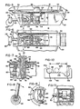
- Fig. 1 is a front elevational view of a steam cooker with door mounting and actuating apparatus embodying the present invention supporting the door in the open position;
- Fig. 2 is a pictorial view of a portion of the steam cooker of Fig. 1 showing the door and the door mounting and actuating apparatus in the closed position;
- Fig. 3 is a top plan view in partial cross section and partially cut away, of the access opening of the steam cooker of Fig. 1 and the door and door mounting and actuating apparatus of the preferred embodiment with the door in an open position partially inserted in the access opening;
- Fig. 4 is a view as in Fig. 3 with the door completely inserted in the access opening, but not yet in sealing engagement with the inside walls of the steam cooker;
- Fig. 5 is a view as in Figs. 3 and 4 with the door in the closed position in sealing engagement with the inside of the rim around the opening of the steam cooker;
- Fig. 6 is a front elevational view in partial cross section of the door and door mounting and actuating apparatus of the preferred embodiment in the door closed position;
- Fig. 7 is an enlarged top view in cross section of a portion of the door and door mounted and actuating apparatus of the preferred embodiment with the door closed;
- Fig. 8 is a partial cross sectional view of the operating handle and end of the rotatable shaft of the preferred embodiment;
- Fig. 9 is a view of the cam and follower of the preferred embodiment looking in the direction of line 9-9 of Fig. 6;
- Fig. 10 is a view of the cam unwrapped and lying in a flat plane and showing various positions of the cam follower; and
- Fig. 11 shows an alternate embodiment of cam and follower.
- In its preferred form the door mounting and actuating apparatus embodying the present invention is utilized to close the access opening on a steam cooker having a housing shown generally as 10 in Fig. 1. Such cookers are commonly utilized in the restaurant and commercial cooking establishments for rapidly cooking or heating food. The access opening 12 of the pressure vessel is supported in the front surface panel of the housing, and is generally circular, provided with a
rim 13 and aninternal seal member 14 in the form of an O-ring.Seal member 14 is mounted around the entire periphery of the access opening on theinside wall 16 to seal the door during cooking. - The
door 18 is generally disc-shaped, warped during fabrication so as to contract in the vertical dimensions unless the door is pressed against theseal member 14 on the inside of the steam cooker. Construction of the door is well known and is referred to in the above referenced U.S. patents and forms no part of the present invention. - When the door is pressed against the
seal member 14, it is stressed to an upward position wherein its peripheral edge is circular and the door forms a spherical segment. The door is pressed against theseal member 14 by pulling outwardly on the central region thereof so that the warp is removed from the door so long as it is held against the seal member. - It can be seen that this particular construction provides a contractible door which allows insertion of the door through the access opening. The door must be able to contract along a diameter sufficiently to pass through the access opening the subsequently to expand inside the access opening. In addition, since the door is supported from a hinged position adjacent the access opening it is helpful to cant the door slightly so that its larger dimension (when warped) can pass freely through the access opening.
- The door is pivotally supported on the front of the
housing 10 by the mounting and actuating apparatus shown generally as 20. This apparatus has a maindoor support member 22 in the form of a channel, generally U-shaped in vertical cross section, opening outward away from the door. Theend portion 24 of this channel is pivotally secured bypin 26 to ahinge bracket 28 mounted to the side of the pressure vessel and extending through the front surface of thehousing 10. Preferably theend portion 24 is provided with ahinge plate 30 which engages thehinge bracket 28 so as to pivot horizontally about thevertical pin 26. Hingeplate 30 is secured to theback portion 31 of the channel-shapedmain support member 22 by welding or the like. - A
decorative cover 32, also generally channel-shaped in cross section, but slightly larger thanmain support member 22, is provided to enclose the door latch mechanism of the apparatus.Cover 32 is placed oversupport member 22 with the opening disposed inwardly towards the door and is secured to themain support member 32 with a plurality of screws (not shown) in order to permit the cover to be removed for servicing of the door latch mechanism. - The
door 18 is secured to the door mounting and actuatingapparatus 20 by a cylindrical sliding member comprising arod 34 as best seen in Fig. 7. A closed nut orend cap 36 is threaded onto the end portion ofrod 34 and holds thedoor 18 against an annular shelf orseat 40 on the rod. An 0-ring seal 42 is provided betweendoor 18 andnut 36 to prevent loss of pressure through the opening 38 in the door. -
Rod 34 is supported in acylindrical guide 44 for inward and outward movement relative to the access opening of the steam cooker. Aball detent member 45 is threaded into the side ofguide 44 and a mating indentation in the side ofrod 34 is provided to prevent rotation of the rod and the door. - The
guide 44 is secured (as by welding) to aplate 46, which in turn is yieldingly supported on theback surface 31 ofmain support member 22 bybolts 48 which are provided with compression springs 50.Plate 46 is a rectangular flat plate which is bent slightly at itsend portion 52, where it is mounted bybolts 48 to the back ofsupport member 22. Thebent portion 52 provides a fulcrum point such that when the rod and thedoor 18 move away from the back ofsupport member 22,plate 46 will cant slightly, thus causing therod 34 anddoor 18 to also be canted slightly so that theedge portion 54 of the door closest to thepivotal end portion 24 of theapparatus 20 will be farther away from thesupport member 22 than theopposite edge portion 56. - The degree of cant necessary in order to permit to door to be inserted through the access opening in the steam cooker will depend upon several factors such as the diameter of the door, diameter of the access opening, swinging radius from the pivot point of the door latch mechanism, and the contracted vertical dimension of the door. For example, using an eight inch diameter door a cant of approximately 4.5 degrees has proved satisfactory when the pivot is approximately five inches from the center of the door.
-
Plate 46 must also be movable laterally of themain support member 22 to accommodate displacement of the rod and door to and from a position horizontally offset in the direction of the pivot or hinge from the center line of the access opening, to allow the door to move freely through the steam cooker when theapparatus 20 is pivoted aboutpin 26. Thus, the openings in theplate 46, through whichbolts 48 extend, are in the form of elongated slots which permit the plate, rod and door to be shifted laterally by a further portion of theapparatus 20, described below. - In order to effect the above referred to movements, shifting the door laterally and moving it inwardly and outwardly relative to the access opening, a
main drive shaft 60 is provided.Shaft 60 is supported onmain support member 22 by a pair of horizontally spacedbrackets main support member 22.Shaft 60 is so supported bybrackets - A
crank member 66 is secured to one end ofshaft 60, androd 34 is connected to thecrank member 66 through an adjustable connectingrod 68. Connectingrod 68 is composed of several parts. Onepart 70 is pivotally secured to apin 72 mounted inrod 34, so thatpart 70 will pivot in a vertical plane upon rotation ofcrank member 66. Anotherpart 74 is threaded at one end ontopart 70, to provide a means for adjusting the length of the connectingrod 68, and has its opposite end mounted on aspherical bearing member 76 which permits angular movement ofpart 74 relative to thecrank member 66. - The
spherical bearing member 76 is mounted to the outer end of crank 66 bybolt 78. Rotation ofcrank member 66 byshaft 60 will thus cause longitudinal movement ofrod 34, to carrydoor 18 toward and away from thesupport member 22. Thespherical bearing member 76, and the loose connection betweenpin 72 andpart 70 permit the piston and the door to be canted byplate 46. - Near the end portion of
shaft 60, adjacent thecrank member 66, there is a pair ofwashers 80 and 82 (Fig. 7) which are secured in axially spaced relation onshaft 60. Extending between these washers is the forkedend 83 of abracket 84. Theopposite end 86 ofbracket 84 is secured to plate 46, betweenbolts 48. This arrangement causes lateral shifting of theplate 46 and therefore shifting and canting of the rod and door, upon axial movement ofshaft 60. - In order to effect movement of the door in an appropriately timed sequence relative to rotation of
shaft 60, a cam and follower mechanism, shown generally as 90, is utilized. In the preferred embodiment thecam follower 92 is a ball bearing roller mounted for rotation on anarm 94 extending perpendicular to thedrive shaft 60 and clamped thereto. Thus, thefollower 92 moves in a circular path in a plane perpendicular to the axis ofdrive shaft 60. Thecam member 96 is cylindrical in form and secured tomain support member 22, such as by welding it tobracket 64. - The
cam member 96 includes acam surface 98 in line with thefollower 92, which is urged into contact with thecam surface 98 by acompression spring 100 disposed concentrically around theshaft 60 and maintained in a compressed state by engagement at one end withbracket 62, and at the other end witharm 94. - The development of
cam surface 98 is shown in Fig. 10. When the door is in the closed position as illustrated in Fig. 5,follower 92 is inposition 92a in Fig. 10. A slight indentation ordetent 102 in thecam surface 98 is provided in this position so that an initial force must be applied toshaft 60 to move thefollower 92 up out of theindentation 102. Thisindentation 102 prevents the door from opening due to a decrease in pressure or a negative pressure within thesteam cooker 10 as often occurs at the end of a cooking cycle. - As the
shaft 60 is rotated from the door closed position,follower 92 moves along the flatcentral portion 104 ofcamming surface 98, whilerod 34 is moved inwardly relative to thesteam cooker 10 by crank 66, thus releasing the edges of the door from their sealing engagement around the access opening. After the door has been moved sufficiently inwardly away from the access opening,roller member 92 moves to position 92c in Fig. 10. - In this position the door is shifted laterally with respect to the
main support member 22 towards thepivot pin 26. This amount of shifting is so designed that the warped door will be aligned for movement through the central region of the access opening of maximum vertical dimensions. As the door is moved outwardly (the follower travelling through theregion 104 of the cam) it will also be canted due to the position ofplate 46, and will be held in the canted position whenfollower 92 is inposition 92c, i.e., in the door fully opened condition. - In order to rotate
shaft 60 to cause the above described movements of the door, ahandle 110 is secured to the outer end ofshaft 60 by means ofcoupling member 112, as best seen in Fig. 8. The outer end ofshaft 60 has a rectangular cross section on which is fitted acoupling member 112 with corresponding mating opening. Themember 112 has a threaded transverse hole in which handle 110 is threaded to engage the end portion ofshaft 60, holding thecoupling member 112 and thehandle 110 in place. Thehandle 110 is so disposed that when the door is in the closed position handle 110 will extend vertically downward. - As previously mentioned, the
cam surface 98 is so designed thatshaft 60 is permitted to rotate through substantially 170 degrees. This results inhandle 110 being disposed 10 degrees off of vertical when the door is in the fully open position. Thus, when the operator pushes downward on the ball member 114 a horizontal component of the downward force will cause the handle to rotate in a vertical plane so as to open the door, once the detent action ofcam section 102 is overcome. Also, the angular relation offollower 92 and crank 66, with respect to the longitudinal axis ofshaft 60, is such that crank 66 is somewhat over-center when the door is fully closed. This precludes movement of the door in response to negative pressures in the vessel as may occur at the end of an operating cycle. - In operation, considering the door to be in a closed position as illustrated in Fig. 5, handle 110 is rotated upward, outwardly away from the front face of the
housing 10. This movement causesfollower 92 to be rotated out of thecam indentation 102 ontocam surface 104 while crank 66moves rod 34, and thusdoor 18, towards the interior of the vessel. As rotation ofhandle 110 is continued andfollower 92 proceeds along theflat cam surface 104,rod 34 continues to move towards the interior of thevessel allowing door 18 to again warp to its contracted position. Also, as the door proceeds to move inwardly away from the access opening due to movement ofroller member 92 alongcamming surface 104,spring plate 46 begins to cant therod 34, and thusdoor 18, so that theend portion 54 of the door adjacent the pivotal position of theapparatus 20 is farthest away from thedoor support member 22. - As rotation of
handle 110 is continued to its uppermost position,follower 92 proceeds along the cam surface intoindentation 106, which causesshaft 60 to be moved axially thus movingrod 34,door 18, andplate 46 laterally towards thepivotal pin 26. With the door in this position it can be pivoted outwardly passing through the access opening. In order to close the door the reverse procedure is utilized. - Fig. 11 shows an alternate embodiment of the invention wherein the mounting of the cam follower and the cam of the preferred embodiment are reversed. Cam 90a is mounted to the
shaft 60 and is rotated by movement of thehandle 110, while thecam follower 92a is mounted stationary on themain support member 32. Thecam follower 92a is a sliding follower instead of the roller shown in Figs. 3-10, and may be built of suitable low friction materials. In a small steam cooker, wherein the door may be of about six inches diameter, and the forces needed to move the door are therefore smaller, this modification may be desirable for lower manufacturing cost.
Claims (11)
Applications Claiming Priority (2)
| Application Number | Priority Date | Filing Date | Title |
|---|---|---|---|
| US833720 | 1977-09-16 | ||
| US05/833,720 US4096968A (en) | 1977-09-16 | 1977-09-16 | Door mounting and actuator for a pressure vessel |
Publications (2)
| Publication Number | Publication Date |
|---|---|
| EP0001336A1 EP0001336A1 (en) | 1979-04-04 |
| EP0001336B1 true EP0001336B1 (en) | 1981-12-02 |
Family
ID=25265103
Family Applications (1)
| Application Number | Title | Priority Date | Filing Date |
|---|---|---|---|
| EP78300348A Expired EP0001336B1 (en) | 1977-09-16 | 1978-09-05 | Door mounting and actuating apparatus for a pressure vessel |
Country Status (4)
| Country | Link |
|---|---|
| US (1) | US4096968A (en) |
| EP (1) | EP0001336B1 (en) |
| CA (1) | CA1078311A (en) |
| DE (1) | DE2861407D1 (en) |
Families Citing this family (15)
| Publication number | Priority date | Publication date | Assignee | Title |
|---|---|---|---|---|
| US4188869A (en) * | 1977-02-23 | 1980-02-19 | Van Den Bergh Engineering Limited | Door for a steam peeler |
| US4253600A (en) * | 1978-05-03 | 1981-03-03 | Standard Oil Company (Indiana) | Fast food container |
| IT7921160V0 (en) * | 1979-03-22 | 1979-03-22 | Bertola Amalia | DEVICE FOR LOCKING THE COVER OF AN OPENING POT TO PREVENT IT FROM OPENING IN THE PRESENCE OF RELATIVE INTERNAL PRESSURE. |
| US4239602A (en) * | 1979-07-23 | 1980-12-16 | Insul Company, Inc. | Ascension pipe elbow lid for coke ovens |
| GR72928B (en) * | 1979-11-23 | 1984-01-12 | Kunz Paul | |
| DE3302109A1 (en) * | 1983-01-22 | 1984-08-09 | Hubert Eirich | DEVICE FOR CLOSING AND CONTINUOUSLY EMPTYING THE CONTAINER OF A PROCESSING MACHINE |
| US4823977A (en) * | 1988-07-06 | 1989-04-25 | Mueller Co. | Abandoning plug for hose nozzle |
| DE19956939A1 (en) * | 1999-11-26 | 2001-05-31 | Eirich Maschf Gustav | Device and method for closing an emptying opening in a rotating container |
| US6611993B2 (en) * | 2000-06-02 | 2003-09-02 | Francis M. Ray | Hinge mechanism |
| US6454117B1 (en) * | 2001-01-04 | 2002-09-24 | Taylor Forge Engineered Systems, Inc. | Manway for pressure vessels |
| ITTO20060119A1 (en) * | 2006-02-21 | 2007-08-22 | Valmar Global Vse Za Sladoled D O O | MACHINE FOR THE PRODUCTION OF ARTISAN ICE CREAM AND AFFINI |
| CN102089217B (en) * | 2007-06-19 | 2013-06-12 | 邓肯·纽曼 | Adjustable closure for a container |
| US20130101372A1 (en) * | 2011-10-19 | 2013-04-25 | Lam Research Ag | Method and apparatus for processing wafer-shaped articles |
| US9260162B2 (en) * | 2012-04-04 | 2016-02-16 | Beacon Finland Ltd Oy | Apparatus, an arrangement and a method for locking an underwater hatch or other removable structure |
| US10632434B2 (en) * | 2014-05-06 | 2020-04-28 | Herbert VEIT | Apparatus for accommodation and dispensing of miscible materials having discharge opening provided with a displacer apparatus |
Family Cites Families (6)
| Publication number | Priority date | Publication date | Assignee | Title |
|---|---|---|---|---|
| FR639195A (en) * | 1927-01-13 | 1928-06-15 | Cie Des Forges D Audincourt Et | Improvements to pots or autoclave containers |
| DE744442C (en) * | 1942-07-24 | 1950-10-03 | Karl G Schmidt | Self-sealing closure for pressure vessels |
| BE495253A (en) * | 1947-12-29 | |||
| US2904212A (en) * | 1956-07-31 | 1959-09-15 | William Vischer | Pressurized vessel |
| US3045861A (en) * | 1959-12-01 | 1962-07-24 | Wesley E Dieter | Closure for evacuated and/or pressurized vessel |
| US3961817A (en) * | 1974-12-23 | 1976-06-08 | Hobart Corporation | Door latch for a pressure vessel |
-
1977
- 1977-09-16 US US05/833,720 patent/US4096968A/en not_active Expired - Lifetime
-
1978
- 1978-07-10 CA CA307,099A patent/CA1078311A/en not_active Expired
- 1978-09-05 DE DE7878300348T patent/DE2861407D1/en not_active Expired
- 1978-09-05 EP EP78300348A patent/EP0001336B1/en not_active Expired
Also Published As
| Publication number | Publication date |
|---|---|
| DE2861407D1 (en) | 1982-01-28 |
| US4096968A (en) | 1978-06-27 |
| CA1078311A (en) | 1980-05-27 |
| EP0001336A1 (en) | 1979-04-04 |
Similar Documents
| Publication | Publication Date | Title |
|---|---|---|
| EP0001336B1 (en) | Door mounting and actuating apparatus for a pressure vessel | |
| US5670025A (en) | Coke oven door with multi-latch sealing system | |
| US3812742A (en) | Jar opener | |
| EP3406947B1 (en) | Valve | |
| EP0408865A3 (en) | Valve gun, in particular for high-pressure cleaning device | |
| US4607760A (en) | Closure for a pressurized chamber | |
| KR20200071726A (en) | Flange assembly for quick change of cooking pot and cooking pot combination device using this flange assembly | |
| US4809542A (en) | Leak testing device for pressure vessels | |
| JPH0516282B2 (en) | ||
| US2966999A (en) | Pressure cooker closure | |
| CN210950128U (en) | Automatic valve opening and closing device for gas tightness detection of kitchen range | |
| CA1039075A (en) | Door latch for a pressure vessel | |
| CN213757933U (en) | Slurry discharge valve and food processor | |
| CN213309029U (en) | Pot cover and pressure cooking utensil provided with same | |
| CN110566714A (en) | Automatic valve opening and closing device for gas tightness detection of kitchen range | |
| CN210961462U (en) | Pressure steam cooker | |
| US3539215A (en) | Closure locking device | |
| CN108679917B (en) | Keep off frame and refrigerator with sealing clamp function | |
| KR101879541B1 (en) | Butterfly valve with overrunning prevention device | |
| JPH0510902Y2 (en) | ||
| US2587947A (en) | Arrangement for maintaining a closure in any of a plurality of open positions | |
| US3052345A (en) | Lunch bucket | |
| CN219221436U (en) | High-temperature high-pressure metal hard sealing butterfly valve | |
| CN220931720U (en) | Closed adjustable atmosphere furnace | |
| GB849326A (en) | Pipe line plugger |
Legal Events
| Date | Code | Title | Description |
|---|---|---|---|
| PUAI | Public reference made under article 153(3) epc to a published international application that has entered the european phase |
Free format text: ORIGINAL CODE: 0009012 |
|
| AK | Designated contracting states |
Designated state(s): DE FR GB |
|
| 17P | Request for examination filed | ||
| GRAA | (expected) grant |
Free format text: ORIGINAL CODE: 0009210 |
|
| AK | Designated contracting states |
Designated state(s): DE FR GB |
|
| REF | Corresponds to: |
Ref document number: 2861407 Country of ref document: DE Date of ref document: 19820128 |
|
| KL | Correction list |
Free format text: 82/04 ZEICHNUNG |
|
| REG | Reference to a national code |
Ref country code: GB Ref legal event code: 732 |
|
| PGFP | Annual fee paid to national office [announced via postgrant information from national office to epo] |
Ref country code: FR Payment date: 19940613 Year of fee payment: 17 |
|
| PGFP | Annual fee paid to national office [announced via postgrant information from national office to epo] |
Ref country code: DE Payment date: 19940615 Year of fee payment: 17 |
|
| PGFP | Annual fee paid to national office [announced via postgrant information from national office to epo] |
Ref country code: GB Payment date: 19940616 Year of fee payment: 17 |
|
| PG25 | Lapsed in a contracting state [announced via postgrant information from national office to epo] |
Ref country code: GB Effective date: 19950905 |
|
| GBPC | Gb: european patent ceased through non-payment of renewal fee |
Effective date: 19950905 |
|
| PG25 | Lapsed in a contracting state [announced via postgrant information from national office to epo] |
Ref country code: FR Effective date: 19960531 |
|
| PG25 | Lapsed in a contracting state [announced via postgrant information from national office to epo] |
Ref country code: DE Effective date: 19960601 |
|
| REG | Reference to a national code |
Ref country code: FR Ref legal event code: ST |
|
| PLBE | No opposition filed within time limit |
Free format text: ORIGINAL CODE: 0009261 |
|
| STAA | Information on the status of an ep patent application or granted ep patent |
Free format text: STATUS: NO OPPOSITION FILED WITHIN TIME LIMIT |