EP0001123A1 - Capsule for cooling semiconductor chips - Google Patents
Capsule for cooling semiconductor chips Download PDFInfo
- Publication number
- EP0001123A1 EP0001123A1 EP78100863A EP78100863A EP0001123A1 EP 0001123 A1 EP0001123 A1 EP 0001123A1 EP 78100863 A EP78100863 A EP 78100863A EP 78100863 A EP78100863 A EP 78100863A EP 0001123 A1 EP0001123 A1 EP 0001123A1
- Authority
- EP
- European Patent Office
- Prior art keywords
- heat
- bellows
- chip
- cooling
- conducting
- Prior art date
- Legal status (The legal status is an assumption and is not a legal conclusion. Google has not performed a legal analysis and makes no representation as to the accuracy of the status listed.)
- Granted
Links
Images


Classifications
-
- H—ELECTRICITY
- H01—ELECTRIC ELEMENTS
- H01L—SEMICONDUCTOR DEVICES NOT COVERED BY CLASS H10
- H01L23/00—Details of semiconductor or other solid state devices
- H01L23/34—Arrangements for cooling, heating, ventilating or temperature compensation ; Temperature sensing arrangements
- H01L23/46—Arrangements for cooling, heating, ventilating or temperature compensation ; Temperature sensing arrangements involving the transfer of heat by flowing fluids
- H01L23/473—Arrangements for cooling, heating, ventilating or temperature compensation ; Temperature sensing arrangements involving the transfer of heat by flowing fluids by flowing liquids
-
- H—ELECTRICITY
- H01—ELECTRIC ELEMENTS
- H01L—SEMICONDUCTOR DEVICES NOT COVERED BY CLASS H10
- H01L23/00—Details of semiconductor or other solid state devices
- H01L23/34—Arrangements for cooling, heating, ventilating or temperature compensation ; Temperature sensing arrangements
- H01L23/42—Fillings or auxiliary members in containers or encapsulations selected or arranged to facilitate heating or cooling
- H01L23/433—Auxiliary members in containers characterised by their shape, e.g. pistons
- H01L23/4332—Bellows
-
- H—ELECTRICITY
- H01—ELECTRIC ELEMENTS
- H01L—SEMICONDUCTOR DEVICES NOT COVERED BY CLASS H10
- H01L23/00—Details of semiconductor or other solid state devices
- H01L23/34—Arrangements for cooling, heating, ventilating or temperature compensation ; Temperature sensing arrangements
- H01L23/44—Arrangements for cooling, heating, ventilating or temperature compensation ; Temperature sensing arrangements the complete device being wholly immersed in a fluid other than air
-
- H—ELECTRICITY
- H01—ELECTRIC ELEMENTS
- H01L—SEMICONDUCTOR DEVICES NOT COVERED BY CLASS H10
- H01L2924/00—Indexing scheme for arrangements or methods for connecting or disconnecting semiconductor or solid-state bodies as covered by H01L24/00
- H01L2924/0001—Technical content checked by a classifier
- H01L2924/0002—Not covered by any one of groups H01L24/00, H01L24/00 and H01L2224/00
Definitions
- the invention relates to a capsule arrangement for cooling semiconductor chips.
- Combined air-liquid cooling systems have therefore been developed especially in connection with very fast data processing systems.
- the components to be cooled are immersed in a tank with cooling liquid. Because of their low boiling point, fluorocarbons are often used as the cooling liquid.
- an encapsulated cooling technology was developed in which the same dielectric material is used separately for each module.
- the US. Patent 3,741,292 shows, by way of example, a module whose heat-generating components are surrounded by a dielectric liquid with a low boiling point and are encapsulated with this liquid. Above the liquid level is an evaporation chamber with fins protruding into the container, which serves as a condenser for the vapors of the dielectric liquid. Outward-reaching fins or cooling fins of the container serve as air-cooled heat sinks for the internal cooling fins.
- Such a module with encapsulated cooling element has a certain inflexibility. So z. B. the coolant of extreme purity and free of all contaminants. The operation is sensitive to all variables which affect the basic process of the Siedan at individual points and the steam condensation. In addition, the concept cannot easily be applied to small parts such as heat-generating components or semiconductor chips.
- an encapsulated gas cooling unit for one or more heat-generating elements to be cooled, such as semiconductor chips.
- the components are arranged on a substrate.
- a cap is sealed to the substrate, which encloses the elements to be cooled that generate heat.
- a protective gas and good thermal guide elements are contained in the sealed volume between the cap and the substrate.
- Each heat conducting element rests on a heat generating element and forms a small gas gap for a low thermal resistance.
- the heat from the heat-conducting elements is conducted to the heat-dissipating cap via an annular gap, which likewise contains an inert gas.
- the working fluid held in the wick is thus in direct contact with the active surface of the semiconductor, which in operation acts as an evaporator part of the closed heat-conducting loop.
- the active surface of the semiconductor which in operation acts as an evaporator part of the closed heat-conducting loop.
- the steam generated in this way is condensed again over corresponding areas of the container which have somewhat lower temperatures than the semiconductor.
- the vapors of the aridity liquid thus ensure an effective heat transfer path to the heat-emitting surface of the container.
- U.S. Patent No. 3,957,107 shows a sealed expandable bladder containing freon and a flexible wick for heat conduction.
- the fixed end of the bellows is attached to a heat dissipating (cold) body.
- the other movable end of the bellows carries a thermally conductive plate, which comes into contact with a temperature-controlled surface (e.g. an oscillator circuit) at a predetermined temperature of the cold body.
- the heat pipe serves an elongated, flexible bellows tube.
- the object of the present invention is to provide an improved capsule arrangement for cooling semiconductor chips and. ⁇ .
- FIG. 1 shows a sectional view through a chip 10 used to cool the solid state technology.
- the current consumed in such circuit chips generates heat which must be dissipated to the outside.
- the various circuits on a chip have different power consumption and the components integrated in the circuits must be kept at an operating temperature which is in a corresponding range by reliable cooling for reliable operation.
- a module cap 16 is with a flange 13 connected, which runs from the edge of the module cap 16 to the Suhstratrand.
- the module cap 16 consists of a material with a high thermal conductivity, such as copper or aluminum. It contains several cutouts or blind holes 20.
- each bellows 21 is in thermal connection with a thermally conductive element or a heat-conducting bolt 22.
- Each heat-conducting bolt 22 has a flat surface which lies on the flat surface of the associated chip opposite it.
- Each bellows 21 springs sufficiently so that the flat surface of the associated heat-conducting bolt lies relatively flat on the flat surface of the chip arranged opposite it.
- the heat-conducting bolts 22 also fit on chips 10 of different heights because of the spring properties of the bellows 21.
- the thermal resistance of the separating surfaces 28 between the heat-conducting bolts and the chip is thus reduced by the "intimate" physical contact between the two flat surfaces of the bolt and the chip .
- a thermally conductive liquid 32 preferably helium
- Helium is used because of its low molecular weight, through which it can easily penetrate into the cavities at the interface between the heat-conducting bolt and the chip and can fill them like any of the bellows 21.
- Each bellows 21 contains perforations at a suitable location so that the helium can be easily and evenly distributed throughout the space defined by the substrate 12 and the module cap 16. This space is designated A1 in FIG. 1.
- Helium is its high thermal conductivity, which is used particularly at the interface between the pin and the chip.
- Helium is also a protective gas, i. H. it is not electrically conductive, it is not toxic, it is not corrosive, it is not flammable and it is not explosive. This gas also has high adhesiveness.
- Other low holicular weight gases such as hydrogen or carbon dioxide can also be used. However, these have undesirable ones. Properties such as the risk of explosion when using hydrogen.
- a module according to the invention can also contain a cooling system, into which a part of each bolt projects. (In FIGS. 1 and 2, the same components are identified with the same reference numbers.)
- each structure consisting of the bellows 21 and the thermally conductive pin 22A / 22B forms a hermetic seal between the chambers A and B.
- each bellows has on the side near the chip to the thermally conductive pin 22A / 22B or in the place of its connection to the recess in FIG the module cap 16B has a hermetic seal.
- Each recess in the module cap 16B is aligned with a chip position on the substrate 12.
- Each pin 22A / 22B has a first part 22B with a flat surface which lies on the essentially likewise flat surface of the associated chip opposite it.
- Each bellows 21 carrying a heat-conducting bolt 22A / 22B springs sufficiently to ensure close surface contact.
- the bolts 22A / 22B are also pressed onto the chips 10 by the spring force of the bellows, which are at different distances from the surface of the suction plate 12.
- the thermal resistance of the interface between the heat-conducting bolt and the chip is reduced by the better physical contact between the pressed flat surfaces of the bolt and the chip.
- a thermally conductive agent 32 preferably helium, is filled through the fill opening 34 into the open space between the substrate 12 and the opposite hermetically sealed structure, which consists of the module wall 16B, the bellows 21 and the bolts 22A / 22B.
- This space containing the cut surfaces between the pin and the chip is identified by the letter A in FIG. 2.
- Volume A1 of FIG. 1 also contains the space within the beige, which is not the case with volume A in FIG. 2.
- FIG. 2 the space or volume between module cap 16A and the hermetically sealed structure , formed by the module wall 16B, the bellows structures 21 and the bolts 22A / 22B, a chamber with the designation B.
- This chamber has an inlet and an outlet through which a suitable coolant such as water is passed.
- the upper part 22A of each bolt 22A / 22B extends into the chamber B and thus into the coolant.
- FIG. 2 shows similar exemplary embodiments of the invention as FIG. 2.
- a structure made of baffles 50 is provided in chamber B in order to direct the coolant from a coolant storage chamber directly onto the structure consisting of bellows and bolts.
- the coolant has a more uniform temperature at the cooling points than in the structure shown in FIG. 2, where the coolant flows successively from one cooling point to another.
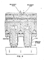
- Fig. 4 the coolant is led from a coolant source, not shown, via channels to each cooling wood.
- the coolant from each bolt position is in the in
- Fig. 4 shown embodiment returned via individual channels to the coolant source.
Landscapes
- Physics & Mathematics (AREA)
- Condensed Matter Physics & Semiconductors (AREA)
- General Physics & Mathematics (AREA)
- Engineering & Computer Science (AREA)
- Computer Hardware Design (AREA)
- Microelectronics & Electronic Packaging (AREA)
- Power Engineering (AREA)
- Cooling Or The Like Of Semiconductors Or Solid State Devices (AREA)
- Cooling Or The Like Of Electrical Apparatus (AREA)
Abstract
In einer Kapselanordnung zum Kühlen von Halbleiterchips (10) ist auf jedem Chip (10) ein wärmeabführender Bolzen (22) positioniert. Der Bolzen (22) verläuft innerhalb eines federnden Balges (21). Das chipferne Ende des Balges (21) ist in einer Aussparung (20) der Kapselanordnung fixiert. Zwischen den Chips (10) und dem Raum ausserhalb des Balges (21), ist ein Kühlmittel I und innerhalb des Balges (21) ist ein weiteres Kühlmittel II vorgesehen. Beide Kühlmittel I und II können gleich sein, vorzugsweise flüssiges Helium oder ungleich sein, wenn der Raum innerhalb des Balges (21) an ein Kühlflüssigkeitssystem angeschlossen ist, welches von dem Kühlmittel I ausserhalb des Balges separiert ist.A heat-dissipating bolt (22) is positioned on each chip (10) in a capsule arrangement for cooling semiconductor chips (10). The bolt (22) runs within a resilient bellows (21). The end of the bellows (21) remote from the chip is fixed in a recess (20) in the capsule arrangement. A coolant I is provided between the chips (10) and the space outside the bellows (21) and a further coolant II is provided within the bellows (21). Both coolants I and II can be the same, preferably liquid helium, or different if the space inside the bellows (21) is connected to a coolant system which is separated from the coolant I outside the bellows.
Description
Die Erfindung betrifft eine Kapselanordnung zum Kühlen von Halbleiterchips.The invention relates to a capsule arrangement for cooling semiconductor chips.
Mit dem Fortschritt der Festkörperelektronik wurden verschiedene verbesserte Einrichtungen zum Ableiten der durch die Festkörperkomponenten erzeugten Wärme untersucht. Bei dem Standardkühlverfahren mit Druckluft treten durch begrenzte Wärmeableitflächen Störprobleme auf, so daß ohne irgendeine technische Hilfe nicht jedes der zahlreichen Bauteile, wie sie auf integrierten Halbleiterchips zu finden sind, im richtigen Betriebstemperaturbereich zu halten ist.With the advancement of solid state electronics, various improved devices for dissipating the heat generated by the solid state components have been investigated. In the standard cooling process with compressed air, problems arise due to limited heat dissipation surfaces, so that without any technical help not every one of the numerous components, such as those found on integrated semiconductor chips, can be kept in the correct operating temperature range.
Daher wurden insbesondere in Verbindung mit sehr schnellen Datenverarbeitungssystemen kombinierte Luft-Flüssigkeits-Kühlsysteme entwickelt. In einem solchen Kühlsystem werden die zu kühlenden Komponenten in einen Tank mit Kühlflüssigkeit eingetaucht. Als Kühlflüssigkeit werden wegen ihres niedrigen Siedepunktes häufig Fluorkohlenstoffe verwendet. In Anbetracht der Probleme bei der Wartung und Packung von in dieser Tauchtechnik gekühlten Komponenten wurde eine gekapselte Kühltechnik entwickelt, bei der dasselbe dielektrische Material für jedes Modul separat verwendet wird.Combined air-liquid cooling systems have therefore been developed especially in connection with very fast data processing systems. In such a cooling system, the components to be cooled are immersed in a tank with cooling liquid. Because of their low boiling point, fluorocarbons are often used as the cooling liquid. In view of the problems with the maintenance and packaging of components cooled in this immersion technology, an encapsulated cooling technology was developed in which the same dielectric material is used separately for each module.
In, der US. Patentschrift 3 741 292 ist als Beispiel ein Modul gezeigt, dessen wärmeerzeugende Komponenten von einer dielektrischen Flüssigkeit mit niedrigem Siedepunkt umgeben sind und mit dieser Füssigkeit gekapselt sind. über dem Flüssigkeitsspiegel liegt ein Verdampfungsraum mit Finnen, die in den Behälter hineinragen, der als Kondensator für die Dämpfe der dielektrischen Flüssigkeit dient. Nach außen reichende Finnen oder Kühlrippen des Behälters dienen als luftgekühlte Wäraeableiter für die internen Kühlrippen. Hin solches Modul mit gekapscitem Kühlelement weist jedoch eine gewisse Inflexibilität auf. So muß z. B. das Kühlmittel von extremer Reinheit und frei von allen Verunreinigungen sein. Der Betrieb ist empfindlich für alle Variablen, die den Crundprozeß des Siedans an einzelnen Punkten und der Dampfkondensation betreffen. Außerdem läßt sich das Konzept nicht ohne weiteres auf kleine Teile anwenden wie etwa auf wärmecrzeugende Komponenten oder Halbleiterchips.In, the US. Patent 3,741,292 shows, by way of example, a module whose heat-generating components are surrounded by a dielectric liquid with a low boiling point and are encapsulated with this liquid. Above the liquid level is an evaporation chamber with fins protruding into the container, which serves as a condenser for the vapors of the dielectric liquid. Outward-reaching fins or cooling fins of the container serve as air-cooled heat sinks for the internal cooling fins. Such a module with encapsulated cooling element, however, has a certain inflexibility. So z. B. the coolant of extreme purity and free of all contaminants. The operation is sensitive to all variables which affect the basic process of the Siedan at individual points and the steam condensation. In addition, the concept cannot easily be applied to small parts such as heat-generating components or semiconductor chips.
In der US. Patentschrift 3 993 123 wird für eines odere mehrere zu kühlende, wärmeerzeugende Elemente wie etwa Halbleiterchips eine gekapselte Gaskühleinheit vorgesehen. Die Kompenenten sind auf einem Substrat angeordnet. Mit dem Substrat ist eine Kappe versiegelt, die die zu kühlenden, wärmeerzeudenden Elemente einschließt. Ein Schutzgas und gute thermische Leitelemente sind in dem versiegelten Volumen zwischen Kappe und Substrat enthalten. Jedes Wärmeleitelement liegt an einem Wärneerzeugungselement an und bildet einen kleinen Gasspalt für einen niedrigen thermischen Widerstand. Die Wärme von den Wärmeleitelementen wird über einen kreisringförmigen Spalt, der gleicherweise ein Schutzgas enthält, an die wärmeableitende Kappe geführt.In the US. Patent 3 993 123, an encapsulated gas cooling unit is provided for one or more heat-generating elements to be cooled, such as semiconductor chips. The components are arranged on a substrate. A cap is sealed to the substrate, which encloses the elements to be cooled that generate heat. A protective gas and good thermal guide elements are contained in the sealed volume between the cap and the substrate. Each heat conducting element rests on a heat generating element and forms a small gas gap for a low thermal resistance. The heat from the heat-conducting elements is conducted to the heat-dissipating cap via an annular gap, which likewise contains an inert gas.
In der US. Patentschrift 3 512 582 wird ein Tauchkühlsystem für modulargepackte Komponenten (wie Halhleiterchips) beschrieben, das ein gemeinsames Gefäß mit einer Flüssigkeit mit niedrigem Siedepunkt enthält. Mehrere modulare Einheiten, dim jeweils eine einzelne Kühlkammer enthalten, sind mit dem gemeinsamen Gefäß über entsprechende Eingangs- und Ausgangsleitungen verbunden. Die einzelnen Kühlkammern und die Eingangsleitungen sind so angeordnet, daß die Flüssigkeit von dem gemeinsamen Gefäß per Schwerkraft durch die Eingangsleitunqen in die einzelnen Kühlkammern fließt. Die Ausgangsleitungen bilden die Flüssiqkeits-Expansionsbahn für die einzelnen Kühlkammern. Die Wärmeerzeugenden Komponenten liegen in jeder Kühlkammer in Wärmeaustauschkontakt mit der niedrigsiedenden Flüssigkeit und werden auf diese (Weise gekühlt. Zu jeder Kühlkammer gehört ein Wärmetauscher zur Entfernung der Wärme aus der niedrigsiedenden Flüssigkeit, so daß besagte elektronische Komponenten ausreichend gekühlt und im wesentlichen auf einer vorgegebenen Temperatur gehalten werden.In the US. Patent 3,512,582 describes an immersion cooling system for modularly packaged components (such as semiconductor chips) which contains a common vessel with a low boiling point liquid. Several modular units, each containing a single cooling chamber, are connected to the common vessel via corresponding input and output lines. The individual cooling chambers and the one Gang lines are arranged so that the liquid flows from the common vessel by gravity through the input lines into the individual cooling chambers. The output lines form the liquid expansion path for the individual cooling chambers. The heat generating components are in heat exchange contact with the low boiling liquid in each cooling chamber and are thus cooled. Each cooling chamber has a heat exchanger for removing the heat from the low boiling liquid so that said electronic components are sufficiently cooled and substantially at a predetermined temperature being held.
In der US. Patentschrift 3 524 497 sind elektronischen Komponenten wie Halbleiterchips oder dergleichen beschrieben, die an einem Ende von wärmeleitenden Kühlzapfen sitzen. Die die Halbleiter tragenden Enden der Kühlzapfen sind an einer Seite mit einer Schaltkarte verbunden. Die Schaltkarte bildet eine Wand eines engen Kanals, durch den Flüssigkeit unter Druck fließt. Die Zapfen verlaufen von der Wand in den Kanal hinein in einem bestimmten Abstand zueinander. Andere mit der gegenüberliegenden Wand verbundene Zapfen laufen ebenfalls zu den Kühlzapfen und in einem bestimmten Abstand gestaffelt parallel dazu in den Kanal hinein. Zusätzliche Zapfen sorgen für eine stärkere Turbulenz der Kühlflüssigkeit um die Wärmeleitzapfen und richten den Strom der Kühlflüssigkeit über eine größere Fläche der Kühlzapfen und vergrößern so die Wärmeübertragung.In the US. Patent 3,524,497 describes electronic components, such as semiconductor chips or the like, which sit at one end of heat-conducting cooling pins. The ends of the cooling pins which carry the semiconductors are connected on one side to a circuit card. The circuit card forms a wall of a narrow channel through which liquid flows under pressure. The pegs run from the wall into the channel at a certain distance from one another. Other pegs connected to the opposite wall also run to the cooling pegs and, staggered at a certain distance, parallel to the duct. Additional pegs provide greater turbulence of the cooling liquid around the heat-conducting pegs and direct the flow of the cooling liquid over a larger area of the cooling pegs, thus increasing the heat transfer.
In der US. Patentschrift 3 586 101 wird ein Füssigkeitkühlsystem für Datenverarbeitungsanlagen beschrieben, in dem mehrere elektronische Komponentenmodule zu kühlen sind, die in Kammern liegen, in denen eine Kühlflüssigkeit durch die Schwerkraft umläuft. Der Zufluß der Kühlflüssigkeit erfolgt von einem Pufferspeicherbchälter her, der oben im Kühlsystem liegt. Eine Phasentrennsäule ist vorgesehen, die mit dem Ausgang einer jeden Modulkammer durch Leitungen gleicher Länge verbunden ist. Die Komponenten innerhalb der Module bringen die Kühlflüssigkeit stellenweise zum sieden. Die Dampfblasen und die Kühlflüssigkeit laufen durch die Leitung und wieder in die Phasentrennsäule hinein, wo die Dampfblasen aufsteigen und die Kühlflässigkeit abtropft. über der Phasentrennsäle liegt ein Kondensator zur Kondensation der Dampfblasen. Das Kondensat und die Flüssigkeit in der Plianentrennsäule werden in das Umlaufsystem zurückgeführt. Im Umlaufsystem liegt eine Kühleinrichtung, um die Kühlflässigkeit auf eine Temperatur unterhalb des Siedepunktes herunterzukühlen.In the US. Patent specification 3,586,101 describes a liquid cooling system for data processing systems, in which several electronic component modules are to be cooled, which are located in chambers in which a cooling liquid circulates due to gravity. The coolant flows in from a buffer storage tank located in the top of the cooling system. A phase separation column is provided which connects to the output of each module chamber through lines of equal length connected is. The components within the modules bring the coolant to a boil in places. The vapor bubbles and the cooling liquid run through the line and back into the phase separation column, where the vapor bubbles rise and the cooling liquid drips off. A condenser for condensing the vapor bubbles is located above the phase separation halls. The condensate and the liquid in the plian separation column are returned to the circulation system. There is a cooling device in the circulation system in order to cool the cooling liquid to a temperature below the boiling point.
In der US. Patentschrift Nr. 3 673 306 wird die Verwendung eines Wärmeleitrohres in einem Metallgehäuse wie in einen Transistorhehälter gezeigt, um Hochleistungshalbleiter zu kühlen, die normalerweise eine große Wärmevorlustleistung haben. Es ist ein elektrisch nicht leitender Docht vorgesehen, der z. B. aus hochgradig reiner Siliciumfrlaswolle besteht und ein Futter für den ganzen Transistorbehälter bildet. Der Docht herührt die aktive Oberfläche des Halbleiters unten am Behälter und die oberen Wände. Bevor der Behälter auf seine Montagebasis gesetzt wird, wird eine angemessene Menge elektrisch nicht leitender und nicht polarwirkender Flüssigkeit - wie eine hochgradig reine organische Flüssigkeit - eingefällt, so daß der Docht ganz gefüllt oder gesättigt ist. Die im Docht festgehaltene Arbeitsflüssigkeit steht somit in direktem Kontakt mit der aktiven Oberfläche des Halbleiters, die im Betrieb als Verdampferteil der geschlossenen Wärmeleit- schleife wirkt. Wenn Flüssigkeit aus diesem Bereich verdampft, findet eine Wärmeübertragung und somit eine Kühlung des Elementes statt. Der so erzeugte Dampf wird über entsprechenden Bereichen des Behälters wieder kondensiert, die etwas niedrigere Temperaturen aufweisen als der Halbleiter. Die Dämpfe der Arheitsflüssigkeit sorgen so für eine effektive Wärmeübertragungsbahn an die wärmeabgebende Fläche des Behälters. In der US. Patentschrift Nr. 3 957 107 wird ein abgedichteter ausdehnbarer Balg gezeigt, der Freon und einen flexiblen Docht für eine Wärmeleitung enthält. Das feste Ende des Balgs ist an einem wärmeableitenden (kalten) Körper befestigt. Das andere bewegliche Ende des Balgs trägt eine thermisch leitende Platte, die bei einer vorgegebenen Temperatur des kalten Körpers mit einer temperaturoeregelten Fläche (z. B. einem Osziallatorkreis) in Berührung tritt.In the US. Patent Specification No. 3,673,306 shows the use of a heat pipe in a metal housing such as in a transistor holder to cool high performance semiconductors which normally have a large heat loss performance. An electrically non-conductive wick is provided which, for. B. consists of highly pure silicon fiber wool and forms a lining for the entire transistor container. The wick comes from the active surface of the semiconductor at the bottom of the container and the top walls. Before the container is placed on its mounting base, an appropriate amount of electrically non-conductive and non-polar liquid - such as a highly pure organic liquid - is dropped in so that the wick is completely filled or saturated. The working fluid held in the wick is thus in direct contact with the active surface of the semiconductor, which in operation acts as an evaporator part of the closed heat-conducting loop. When liquid evaporates from this area, heat is transferred and thus the element is cooled. The steam generated in this way is condensed again over corresponding areas of the container which have somewhat lower temperatures than the semiconductor. The vapors of the aridity liquid thus ensure an effective heat transfer path to the heat-emitting surface of the container. In the US. U.S. Patent No. 3,957,107 shows a sealed expandable bladder containing freon and a flexible wick for heat conduction. The fixed end of the bellows is attached to a heat dissipating (cold) body. The other movable end of the bellows carries a thermally conductive plate, which comes into contact with a temperature-controlled surface (e.g. an oscillator circuit) at a predetermined temperature of the cold body.
Im IBM Technical Disclosure Bulletin Nr. 11, Band '17, vom April 1975 wird auf Seite 3313 die Wärmeleitung und der thermische Kontakt zwischen einem Wärmeahleiter und einem IIalbleitermodul beschrieben. Der Wäirmeleitung dient dabei ein längliches, flexibles Balgenrohr.In IBM Technical Disclosure Bulletin No. 11, Volume '17, dated April 1975, on page 3313, the heat conduction and the thermal contact between a heat conductor and a semiconductor conductor are described. The heat pipe serves an elongated, flexible bellows tube.
Im IBM Technical Disclosure Bulletin, Nr. 8, Band 14, Jan. 1972 wird auf Seite 2533 beschrieben, wie eine Druckänderung durch einen Balg kompensiert wird, der ganz in der Flüssigkeit eingetaucht ist. Der Balg hat zum Betrieb eine Öffnung in die umgebende Luft.In IBM Technical Disclosure Bulletin, No. 8,
Die Aufgabe der vorliegenden Erfindung besteht in der Schaffung einer verbesserten Kapselanordnung zum Kühlen von Halbleiterchips u. ä.The object of the present invention is to provide an improved capsule arrangement for cooling semiconductor chips and. Ä.
Diese Aufgabe der Erfindung wird in vorteilhafter Weise durch die im kennzeichnenden Teil des Anspruches 1 genannten Maßnahmen gelöst. Weitere Merkmale der Erfindung sind den Unteransprüchen zu entnehmen.This object of the invention is achieved in an advantageous manner by the measures mentioned in the characterizing part of
Ausführungsbeispiele der Erfindung sind in den Zeichnungen dargestellt und werden im folgenden näher beschrieben.Embodiments of the invention are shown in the drawings and are described in more detail below.
Es zeigen:
- Fig. 1 eine Schnittansicht eines Ausfünrungsbeispieles der Erfindung;
- Fig. 1A eine vergrößerte Ansicht eines Teiles der in Fig. 1 dargestellten Struktur,
- Fig. 2 eine Schnittansicht eines anderen Ausführungsbeispieles der Erfindung,
- Fig. 2A eine vergrößerte Ansicht eines Teiles der in Fig. 2 gezeigten Struktur,
- Fig. 3 eine Schnittansicht eines weiteren Ausführungsbeispiels der Erfindung mit einer Leitflächenstruktur und
- Fig. 4 eine Schnittansicht eines anderen Ausführungsbeispiels der Erfindung mit einer Kanalstruktur des Kühlflüssiqkeitssystems.
- 1 is a sectional view of an exemplary embodiment of the invention;
- 1A is an enlarged view of a portion of the structure shown in FIG. 1.
- 2 is a sectional view of another embodiment of the invention,
- 2A is an enlarged view of part of the structure shown in FIG. 2,
- 3 shows a sectional view of a further exemplary embodiment of the invention with a guide surface structure and
- Fig. 4 is a sectional view of another embodiment of the invention with a channel structure of the cooling liquid system.
Fig. 1 zeigt eine Schnittansicht durch ein zum Kühlen der in Festkörpertechnik ausgeführten Chips 10. Der in solchen Schaltungschips verbrauchte Strom erzeugt bekanntlich Wärme, die nach außen abgeleitet werden muß. Die verschiedenen Schaltungen auf einem Chip haben unterschiedlichen Stromverbrauch und die in den Schaltungen integrierten Komponenten müssen für einen zuverlässigen Betrieb durch eine angemessene Kühlung auf einer Betriebtemperatur gehalten werden, die in einem entsprechenden Bereich liegt.1 shows a sectional view through a
Auf einer Seite eines im allgemeinen aus Keramikmaterial bestehenden Substrates 12 sind Chips 1O montiert, deren Anschlußstifte 14 auf der anderen Seite des Substrats liegen. Die integrierten Schaltungen auf den Chips sind in bekannter Technik durch Lötverbindungen 10A mit den nicht dargestellten Leitern im Substrat 12 verbunden. Diese Leiter wiederum sind wahlweise mit den Anschlußstiften 14 verbunden. Die Anschlußstifte 14 dienen dem Einstecken des Moduls in eine Schaltkarte (nicht dargestellt). Eine Modulkappe 16 ist mit einem Flansch 13 verbunden, der vom Rand der Mlodulkappe 16 zum Suhstratrand verläuft. Die Modulkappe 16 besteht aus einem Material mit einem hohen Wärmeleitwert wie Kupfer oder Aluminium. Sie enthält mehrere Aussparungen bzw. Sacklöcher 20. Diese sind in der Modulkappe 16 so angeordnet, daß sie den Chippositionen auf dem Substrat 12 entsprechen. Jede Aussparung in der Modulkappe liegt einem Chip 10 gegenüber und ist auf dieses ausgerichtet. Die Aussparungen 20 in der Modulkappe 16 sind so ausgelegt, daß sie genau einen federnden, thermisch leitenden Balg 21 aufnehmen können. Gemäß der Darstellung in Fig. 1 steht jeder Balg 21 in thermischer Verbindung mit einem thermisch leitenden Element bzw. einem wärmeleitenden Bolzen 22. Jeder wärmeleitende Bolzen 22 hat eine plane Oberfläche, die auf der ihn gegenüberliegenden planen Oberfläche des zugehörigen Chip aufliegt. Jeder Balg 21 federt genügend, so daß die plane Oberfläche des zugehörigen wärmeleitenden Bolzens relativ eben auf der planen Oberfläche des ihm gegenüber angeordneten Chips aufliegt. Die wärmeleitenden Bolzen 22 passen auch auf Chips 10 unterschiedlicher Höhe wegen der Federeigenschaft der Balgen 21. Der thermische Widerstand der Trennflächen 28 zwischen den wärmeleitenden Bolzen und dem Chip wird somit durch den "innigen" physikalischen Kontakt zwischen den beiden planen Flächen von Bolzen und Chip reduziert.On one side of a substrate 12, which is generally made of ceramic material, chips 10 are mounted, the connection pins 14 of which lie on the other side of the substrate. The integrated circuits on the chips are connected in a known technique by
Eine thermisch leitende Flüssigkeit 32, vorzugsweise Helium, wird in den leeren Raum zwischen dem Substrat und der Modulkappe durch die Einfüllöffnung 34 eingefüllt. Es wird Helium verwendet wegen seines niedrigen Molikulargewichtes, durch das es leicht in die Hohlräume an der Schnittfläche zwischen dem wärmeleitenden Bolzen und dem Chip eindringen und diese ebenso wie jeden der Balgen 21 füllen kann. Jeder Balg 21 enthält an geeigneter Stelle Perforationen, damit sich das Helium in dem ganzen Raum, der durch das Substrat 12 und die Modulkappe 16 definiert ist, leicht und gleichmäßig verteilen kann. Dieser Raum ist in Fig. 1 mit A1 bezeichnet.A thermally conductive liquid 32, preferably helium, is filled into the empty space between the substrate and the module cap through the
Eine physikalische Eigenschaft von Helium ist seine hohe Wärmeleitfähigkeit, die besonders an der Schnittstelle zwischen Bolzen und Chip ausgenutzt wird. Weiterhin ist Helium ein Schutzgas, d. h. es ist elektrisch nicht leitend, es ist nicht giftig, nicht korrodierend, nicht brennbar und nicht explosiv. Dieses Gas hat außerdem eine hohe Haftfähigkeit. Andere Gase mit niedrigen Holikulargewicht wie Wasserstoff oder Kohlendioxyd können ebenso verwendet werden. Diese haben jedoch unerwünschte. Eigenschaften wie beispielsweise die Explosionsgefahr bei der Verwendung von Wasserstoff.One of the physical properties of helium is its high thermal conductivity, which is used particularly at the interface between the pin and the chip. Helium is also a protective gas, i. H. it is not electrically conductive, it is not toxic, it is not corrosive, it is not flammable and it is not explosive. This gas also has high adhesiveness. Other low holicular weight gases such as hydrogen or carbon dioxide can also be used. However, these have undesirable ones. Properties such as the risk of explosion when using hydrogen.
Ein erfindungsgemäßer Modul kann auch ein Kühlsystem enthalten, in das ein Teil eines jeden Bolzens hineinragt. (In den Fign. 1 und 2 sind gleiche Bauelemente mit den gleichen Bezugszahlen gekennzeichnet.)A module according to the invention can also contain a cooling system, into which a part of each bolt projects. (In FIGS. 1 and 2, the same components are identified with the same reference numbers.)
In Fig. 2 wird die Ausrichtung der wärmeleitenden Bolzen 22A, 22B auf die plane Chipoberfläche wie in dem Ausführungsbeispiel in Fig. 1 durch die Wirkung der federnden Balgen 21 verstärkt. In rig. 2 bildet jede aus dem Balg 21 und dem wärmeleitenden Polzen 22A/22B bestehende Struktur eine hermetischen Abdichtung zwischen den Kammern A und B. Insbesondere weist jeder Balg an der chipnahen Seite zum wärmeleitenden Bolzen 22A/22B oder an der Stelle seiner Verbindung mit der Aussparung in der Modulkappe 16B eine hermetische Dichtung auf. Jede Aussparung in der Modulkappe 16B ist auf eine Chipposition auf dem Substrat 12 ausgerichtet. Jeder Bolzen 22A/22B hat einen ersten Teil 22B mit einer planen Oberfläche, die auf der ihm gegenüberliegenden im wesentlichen ebenfalls planen Oberflächen des zugehörigen Chip aufliegt. Jeder einen wärmeleitenden Bolzen 22A/22B tragende Balg 21 federt genügend, damit ein enger Oberflächenkontakt gewährleistet ist. Wie in dem. in Fig. 1 gezeigten Ausführungsbeispiel werden durch die Federkraft der Balgen die Bolzen 22A/22B auch auf die Chips 10 gedrückt, die von der Oberfläche des Suhstrates 12 unterschiedlich weit entfernt sind. In dem in Fig. 2 gezeigten Ausführungsbeispiel wird ebenso wie in dem Beispiel der Fig. 1 der thermische Widerstand der Schnittfläche zwischen dem wärmeleitenden Bolzen und den Chip durch den besseren physikalischen Kontakt zwischen den aufeinandergedrückten planen Oberflächen des Bolzens und des Chips reduziert. In Fig. 2 wird ein thermisch leitendes Mittel 32, vorzugsweise Helium durch die Einfüllüffnung 34 in den offenen Raum zwischen dem Substrat 12 und der gegenüberliegenden hermetisch abgedichteten Struktur eingefüllt, die aus der Modulwand 16B, den Balg 21 und den Bolzen 22A/22B besteht. Dieser die Schnittflächen zwischen Bolzen und Chip enthaltende Raum ist in Fig. 2 mit den Zeichen A gekennzeichnet. (Das Volumen A1 der Fig. 1 enthält auch den Raum innerhalb des Beiges, was bei den Volumen A in Fig. 2 nicht der Fall ist.) In Fig. 2 ist der Raum oder das Volumen zwischen der Modulkappe 16A und der hermetisch abgedichteten Struktur, gebildet durch die Modulwand 16B, die Balgstrukturen 21 und die Bolzen 22A/22B eine Kammer mit der Bezeichnung B. Diese Kammer hat einen Einlauf und einen Auslauf, durch den ein geeignetes Kühlmittel wie etwa Wasser geführt wird. Der obere Teil 22A eines jeden Bolzen 22A/22B reicht in die Kammer B und somit in das Kühlmittel hinein.In FIG. 2, the alignment of the heat-conducting
Die Fign. 3 und 4 zeigen ähnliche Ausführungsbcispiele der Erfindung wie die Fig. 2.The figures 3 and 4 show similar exemplary embodiments of the invention as FIG. 2.
In Fig. 3 ist in der Kammer B eine Struktur aus Leitblechen 50 vorgesehen, um das Kühlmittel von einer Kühlmittelvorratskammer direkt auf die aus Balgen und Bolzen bestehende Struktur zu leiten. Somit hat das Kühlmittel an den Kühlstellen eine gleichmäßigere Temperatur als in der in Fig. 2 gezeigten Struktur, wo das Kühlmittel nacheinander von einer Kühlstelle zu anderen fließt.In FIG. 3, a structure made of
In Fig. 4 wird das Kühlmittel von einer nicht dargestellten Kühlmittelquelle über Kanäle an jeden Kühlholzen herangeleitet. Das Kühlmittel von jeder Bolzenposition wird in dem inIn Fig. 4, the coolant is led from a coolant source, not shown, via channels to each cooling wood. The coolant from each bolt position is in the in
Fig. 4 gezeigten Ausführungsbeispiel über einzelne Kanäle an die Kühlmittelquelle zurückgeführt.Fig. 4 shown embodiment returned via individual channels to the coolant source.
Die Kombination der hohen Wärmeleitfähigkeit von Helium und seiner Fähigkeit zum Ausfüllen von Hohlräumen zusammen mit den verbesserten physikalischen Kontakt der Kontaktflächen zwischen dem wärmeleitenden Bolzen und dem Chip durch die Balgenstruktur wird in jedem Ausführungsbeispiel der Erfindung dazu genutzt, die thermische Verbindung an der Schnittfläche zwischen Chip und Bolzen und somit die Kühlung des Moduls zuThe combination of the high thermal conductivity of helium and its ability to fill voids together with the improved physical contact of the contact surfaces between the heat-conducting bolt and the chip through the bellows structure is used in each exemplary embodiment of the invention to provide the thermal connection at the interface between the chip and Bolts and thus the cooling of the module too
Claims (9)
daß ein Wämeabführelement (22) in engem thermischen Kontakt zum Chip (10) vorgesehen ist,
welches (22) von einem federnden, wärmeleitenden, balgförmigen Element (21) auf dem Chip (10) positionierbar und innerhalb dessen (21) angeordnet ist,
daß das chipferne Ende des balgstrulaurierten Elementes (21) in einer Aussparung (20) eines wärmeleitenden Teiles (16, 1GB) der Kapselanordnung fixiert ist, und daß innerhalb der Kapselanordnung ein Kühlmedium außerhalb und ein Kühlmedium innerhalb des balgstrukturierten Elementes (21) vorgesehen ist.1. capsule arrangement for cooling semiconductor chips, characterized in that
that a heat dissipation element (22) is provided in close thermal contact with the chip (10),
which (22) can be positioned on the chip (10) by a resilient, heat-conducting, bellows-shaped element (21) and is arranged inside the chip (10),
that the end of the bellows-stripped element (21) remote from the chip is fixed in a recess (20) of a heat-conducting part (16, 1GB) of the capsule arrangement, and that a cooling medium outside and a cooling medium inside the bellows-structured element (21) is provided within the capsule arrangement.
dadurch gekennzeichnet,
daß als elektrisch nichtleitendes Kühlmedium ein wärmeleitendes Gas oder eine wärmeleitende Flüssigkeit verwendbar ist, und daß das balgstrukturierte Element (21) öffnungen für den Durchtritt des Kühlmediums aufweisen.2. Arrangement according to claim 1,
characterized,
that a heat-conducting gas or a heat-conducting liquid can be used as the electrically non-conductive cooling medium, and that the bellows-structured element (21) has openings for the passage of the cooling medium.
dadurch gekennzeichnet,
daß als Kühlmedium außerhalb des balgstrukturierten Elementes (21) ein verflüssigtes, wärmeleitendes Gas und daß als Kühlmedium innerhalb des balgstrukturierten Elementes (21) eine Kühlflussinkeit verwendbar ist.3. Arrangement according to claim 1,
characterized,
that as a cooling medium outside the bellows-structured element (21) is a liquefied, heat-conducting gas and that a cooling flow incidence can be used as the cooling medium within the bellows-structured element (21).
dadurch gekennzeichnet,
daß das balgstrukturierte Element (21) an seinem chipfernen Ende zu einem Kühlflüssigkeitsyntem (42) hin offen ist und daß durch das balgstrukturierte Element (21) mit dem Wärmeahführelenent (22) das wärmeleitende Gas bzw. die wärmeleitende Flüssigkeit und die Kühlflüssigkeit voneinander getrennt sind.4. Arrangement according to claim 3,
characterized,
that the balgstrukturierte element (21) is open at its chip distal end to a Kühlflüssigkeitsyntem (42) and that are respectively the heat-conducting liquid and the cooling liquid separated by the balgstrukturierte element (21) with the Wärmeahführelenent (22), the heat conductive G as .
dadurch gekennzeichnet,
daß das Kühlflüssigkeitssystem (42) Leitflächenstrukturen (50) oder Kanalstrukturen aufweist, durch die die Kühlflüssigkeit an den Wärmeabührelement (22) vorbeiführbar ist.5. Arrangement according to claim 4,
characterized,
that the coolant system (42) has guide surface structures (50) or channel structures through which the coolant can be guided past the heat dissipation element (22).
dadurch gekennzeichnet,
daß die thermische Kontnktfläche zwischen dem Wärmeabführelement (22) und den Halbleiterchip (10) plan ist.6. Arrangement according to one of claims 1 to 5,
characterized,
that the thermal contact surface between the heat dissipation element (22) and the semiconductor chip (10) is flat.
dadurch gekennzeichnete,
daß das Wämeabführelment (22) Bolzenform aufweist.7. Arrangement according to claim 6,
characterized by
that the heat removal element (22) has a bolt shape.
dadurch gekennzeichnet, daß pro Kapselanordnung mehrere Chips mit jeweils zugeordneten balgstrukturiertem Element (21) vorgesehen sind.9. Arrangement according to one of claims 1 to 8 ',
characterized, that several chips are provided per capsule arrangement, each with associated bellows-structured element (21).
Applications Claiming Priority (2)
| Application Number | Priority Date | Filing Date | Title |
|---|---|---|---|
| US05/832,716 US4138692A (en) | 1977-09-12 | 1977-09-12 | Gas encapsulated cooling module |
| US832716 | 1977-09-12 |
Publications (2)
| Publication Number | Publication Date |
|---|---|
| EP0001123A1 true EP0001123A1 (en) | 1979-03-21 |
| EP0001123B1 EP0001123B1 (en) | 1982-06-16 |
Family
ID=25262433
Family Applications (1)
| Application Number | Title | Priority Date | Filing Date |
|---|---|---|---|
| EP78100863A Expired EP0001123B1 (en) | 1977-09-12 | 1978-09-09 | Capsule for cooling semiconductor chips |
Country Status (6)
| Country | Link |
|---|---|
| US (1) | US4138692A (en) |
| EP (1) | EP0001123B1 (en) |
| JP (1) | JPS5444479A (en) |
| CA (1) | CA1097788A (en) |
| DE (1) | DE2861901D1 (en) |
| IT (1) | IT1174385B (en) |
Cited By (11)
| Publication number | Priority date | Publication date | Assignee | Title |
|---|---|---|---|---|
| EP0068142A2 (en) * | 1981-06-30 | 1983-01-05 | International Business Machines Corporation | Gas cooled modules for electrical components |
| EP0151068A2 (en) * | 1984-01-26 | 1985-08-07 | Fujitsu Limited | Cooling system for electronic circuit device |
| EP0168677A2 (en) * | 1984-07-12 | 1986-01-22 | International Business Machines Corporation | A cooling system for integrated circuit chips |
| EP0193747A2 (en) * | 1985-03-04 | 1986-09-10 | Hitachi, Ltd. | Device for cooling integrated circuit chip |
| EP0196054A2 (en) * | 1985-03-26 | 1986-10-01 | Hitachi, Ltd. | Semiconductor module cooling structure |
| EP0219674A1 (en) * | 1985-09-20 | 1987-04-29 | Fujitsu Limited | Cooling device for electronic parts |
| EP0243793A2 (en) * | 1986-04-30 | 1987-11-04 | International Business Machines Corporation | Hydraulic manifold for water cooling of multi-chip electric modules |
| EP0343936A2 (en) * | 1988-05-24 | 1989-11-29 | Fujitsu Limited | Module sealing structure |
| WO1991006958A1 (en) * | 1989-10-30 | 1991-05-16 | Dolphin Server Technology A.S | A method and a means for cooling electronic components |
| WO1991018426A1 (en) * | 1990-05-16 | 1991-11-28 | Chloride Silent Power Limited | A thermal shunt for a battery |
| CN101324533B (en) * | 2007-06-13 | 2011-07-20 | 中国科学院工程热物理研究所 | System for observing and measuring multiphase system microjet phase-change energy mass transfer course |
Families Citing this family (98)
| Publication number | Priority date | Publication date | Assignee | Title |
|---|---|---|---|---|
| US4203129A (en) * | 1978-07-11 | 1980-05-13 | International Business Machines Corporation | Bubble generating tunnels for cooling semiconductor devices |
| US4258383A (en) * | 1978-12-22 | 1981-03-24 | Rca Corporation | Minimum pressure drop liquid cooled structure for a semiconductor device |
| US4268850A (en) * | 1979-05-11 | 1981-05-19 | Electric Power Research Institute | Forced vaporization heat sink for semiconductor devices |
| US4395728A (en) * | 1979-08-24 | 1983-07-26 | Li Chou H | Temperature controlled apparatus |
| US4263965A (en) * | 1980-01-21 | 1981-04-28 | International Business Machines Corporation | Leaved thermal cooling module |
| US4330812A (en) * | 1980-08-04 | 1982-05-18 | The United States Of America As Represented By The Secretary Of The Navy | Circuit board electronic component cooling structure with composite spacer |
| JPS57182741A (en) * | 1981-05-07 | 1982-11-10 | Dainippon Printing Co Ltd | Photomask blank plate |
| JPS57182740A (en) * | 1981-05-07 | 1982-11-10 | Dainippon Printing Co Ltd | Photomask |
| US4441075A (en) * | 1981-07-02 | 1984-04-03 | International Business Machines Corporation | Circuit arrangement which permits the testing of each individual chip and interchip connection in a high density packaging structure having a plurality of interconnected chips, without any physical disconnection |
| JPS5892241A (en) * | 1981-11-28 | 1983-06-01 | Mitsubishi Electric Corp | Package for semiconductor device |
| US4503386A (en) * | 1982-04-20 | 1985-03-05 | International Business Machines Corporation | Chip partitioning aid (CPA)-A structure for test pattern generation for large logic networks |
| US4468717A (en) * | 1982-06-09 | 1984-08-28 | Sperry Corporation | Apparatus for cooling integrated circuit chips |
| US4450505A (en) * | 1982-06-09 | 1984-05-22 | Sperry Corporation | Apparatus for cooling integrated circuit chips |
| JPS59200495A (en) * | 1983-04-27 | 1984-11-13 | 株式会社日立製作所 | Multichip module |
| JPS6092642A (en) * | 1983-10-26 | 1985-05-24 | Mitsubishi Electric Corp | Forced cooling device for semiconductor device |
| JPH0673364B2 (en) * | 1983-10-28 | 1994-09-14 | 株式会社日立製作所 | Integrated circuit chip cooler |
| CA1227886A (en) * | 1984-01-26 | 1987-10-06 | Haruhiko Yamamoto | Liquid-cooling module system for electronic circuit components |
| US4557514A (en) * | 1984-07-18 | 1985-12-10 | At&T Technologies, Inc. | Vacuum pick and place robotic hand |
| JPS6178572A (en) * | 1984-09-25 | 1986-04-22 | Toyota Motor Corp | Dislocation detecting method in automatic arc welding |
| US4632294A (en) * | 1984-12-20 | 1986-12-30 | International Business Machines Corporation | Process and apparatus for individual pin repair in a dense array of connector pins of an electronic packaging structure |
| US4920574A (en) * | 1985-10-04 | 1990-04-24 | Fujitsu Limited | Cooling system for an electronic circuit device |
| US4750086A (en) * | 1985-12-11 | 1988-06-07 | Unisys Corporation | Apparatus for cooling integrated circuit chips with forced coolant jet |
| US4758926A (en) * | 1986-03-31 | 1988-07-19 | Microelectronics And Computer Technology Corporation | Fluid-cooled integrated circuit package |
| KR890007419A (en) * | 1987-10-21 | 1989-06-19 | 미다가쓰시게 | Semiconductor module and its cooling device |
| US4951740A (en) * | 1988-06-27 | 1990-08-28 | Texas A & M University System | Bellows heat pipe for thermal control of electronic components |
| US4912600A (en) * | 1988-09-07 | 1990-03-27 | Auburn Univ. Of The State Of Alabama | Integrated circuit packaging and cooling |
| US4879629A (en) * | 1988-10-31 | 1989-11-07 | Unisys Corporation | Liquid cooled multi-chip integrated circuit module incorporating a seamless compliant member for leakproof operation |
| US4910642A (en) * | 1988-12-05 | 1990-03-20 | Sundstrand Corporation | Coolant activated contact compact high intensity cooler |
| US5040051A (en) * | 1988-12-05 | 1991-08-13 | Sundstrand Corporation | Hydrostatic clamp and method for compression type power semiconductors |
| US5016090A (en) * | 1990-03-21 | 1991-05-14 | International Business Machines Corporation | Cross-hatch flow distribution and applications thereof |
| US5097385A (en) * | 1990-04-18 | 1992-03-17 | International Business Machines Corporation | Super-position cooling |
| JPH07114250B2 (en) * | 1990-04-27 | 1995-12-06 | インターナショナル・ビジネス・マシーンズ・コーポレイション | Heat transfer system |
| US5046552A (en) * | 1990-07-20 | 1991-09-10 | Minnesota Mining And Manufacturing | Flow-through heat transfer apparatus with movable thermal via |
| US5212626A (en) * | 1990-11-09 | 1993-05-18 | International Business Machines Corporation | Electronic packaging and cooling system using superconductors for power distribution |
| JPH06342990A (en) * | 1991-02-04 | 1994-12-13 | Internatl Business Mach Corp <Ibm> | Integrated cooling system |
| US5205348A (en) * | 1991-05-31 | 1993-04-27 | Minnesota Mining And Manufacturing Company | Semi-rigid heat transfer devices |
| JP2995590B2 (en) * | 1991-06-26 | 1999-12-27 | 株式会社日立製作所 | Semiconductor cooling device |
| US5177667A (en) * | 1991-10-25 | 1993-01-05 | International Business Machines Corporation | Thermal conduction module with integral impingement cooling |
| CA2088821C (en) * | 1992-02-05 | 1999-09-07 | Hironobu Ikeda | Cooling structure for integrated circuit |
| US5206791A (en) * | 1992-02-07 | 1993-04-27 | Digital Equipment Corporation | Bellows heat pipe apparatus for cooling systems |
| US5269372A (en) * | 1992-12-21 | 1993-12-14 | International Business Machines Corporation | Intersecting flow network for a cold plate cooling system |
| US5513070A (en) * | 1994-12-16 | 1996-04-30 | Intel Corporation | Dissipation of heat through keyboard using a heat pipe |
| JP3233808B2 (en) * | 1995-03-17 | 2001-12-04 | 富士通株式会社 | Electronic package cooling system |
| US5605574A (en) * | 1995-09-20 | 1997-02-25 | Kabushiki Kaisha Toshiba | Semiconductor wafer support apparatus and method |
| US5923085A (en) * | 1996-05-02 | 1999-07-13 | Chrysler Corporation | IGBT module construction |
| US5847366A (en) * | 1996-06-18 | 1998-12-08 | Intel Corporation | Apparatus and method for controlling the temperature of an integrated circuit under test |
| US6031286A (en) * | 1997-02-28 | 2000-02-29 | International Business Machines Corporation | Semiconductor structures containing a micro pipe system therein |
| US6152213A (en) | 1997-03-27 | 2000-11-28 | Fujitsu Limited | Cooling system for electronic packages |
| US5880524A (en) * | 1997-05-05 | 1999-03-09 | Intel Corporation | Heat pipe lid for electronic packages |
| JP2001053205A (en) * | 1999-08-05 | 2001-02-23 | Hitachi Ltd | Sealing and cooling device for multichip module |
| EP1085287A3 (en) * | 1999-09-17 | 2002-01-16 | SANYO ELECTRIC Co., Ltd. | Heat carrier |
| US6388882B1 (en) | 2001-07-19 | 2002-05-14 | Thermal Corp. | Integrated thermal architecture for thermal management of high power electronics |
| JP2003051689A (en) * | 2001-08-06 | 2003-02-21 | Toshiba Corp | Heating element cooling unit |
| US20030033398A1 (en) * | 2001-08-10 | 2003-02-13 | Sun Microsystems, Inc. | Method, system, and program for generating and using configuration policies |
| US20030033346A1 (en) * | 2001-08-10 | 2003-02-13 | Sun Microsystems, Inc. | Method, system, and program for managing multiple resources in a system |
| US6433413B1 (en) | 2001-08-17 | 2002-08-13 | Micron Technology, Inc. | Three-dimensional multichip module |
| US7252139B2 (en) * | 2001-08-29 | 2007-08-07 | Sun Microsystems, Inc. | Method and system for cooling electronic components |
| US6747347B2 (en) * | 2001-08-30 | 2004-06-08 | Micron Technology, Inc. | Multi-chip electronic package and cooling system |
| US7133907B2 (en) * | 2001-10-18 | 2006-11-07 | Sun Microsystems, Inc. | Method, system, and program for configuring system resources |
| US6965559B2 (en) * | 2001-10-19 | 2005-11-15 | Sun Microsystems, Inc. | Method, system, and program for discovering devices communicating through a switch |
| US6587345B2 (en) * | 2001-11-09 | 2003-07-01 | International Business Machines Corporation | Electronic device substrate assembly with impermeable barrier and method of making |
| US7385821B1 (en) * | 2001-12-06 | 2008-06-10 | Apple Inc. | Cooling method for ICS |
| DE10164522B4 (en) * | 2001-12-17 | 2005-05-25 | Siemens Ag | Clamping device and semiconductor device with a clamping device |
| US20030135609A1 (en) * | 2002-01-16 | 2003-07-17 | Sun Microsystems, Inc. | Method, system, and program for determining a modification of a system resource configuration |
| EP1331665B1 (en) * | 2002-01-26 | 2009-10-14 | Danfoss Silicon Power GmbH | Cooling apparatus |
| US7100389B1 (en) | 2002-07-16 | 2006-09-05 | Delta Design, Inc. | Apparatus and method having mechanical isolation arrangement for controlling the temperature of an electronic device under test |
| US7103889B2 (en) | 2002-07-23 | 2006-09-05 | Sun Microsystems, Inc. | Method, system, and article of manufacture for agent processing |
| US20040022200A1 (en) * | 2002-07-31 | 2004-02-05 | Sun Microsystems, Inc. | Method, system, and program for providing information on components within a network |
| US7143615B2 (en) | 2002-07-31 | 2006-12-05 | Sun Microsystems, Inc. | Method, system, and program for discovering components within a network |
| US20040024887A1 (en) * | 2002-07-31 | 2004-02-05 | Sun Microsystems, Inc. | Method, system, and program for generating information on components within a network |
| US7035104B2 (en) * | 2002-08-06 | 2006-04-25 | Mudawar Thermal Systems Inc. | Apparatus for heat transfer and critical heat flux enhancement |
| US6953227B2 (en) * | 2002-12-05 | 2005-10-11 | Sun Microsystems, Inc. | High-power multi-device liquid cooling |
| US6975028B1 (en) | 2003-03-19 | 2005-12-13 | Delta Design, Inc. | Thermal apparatus for engaging electronic device |
| FR2864211B1 (en) * | 2003-12-23 | 2007-01-12 | Christian Muller | THERMAL EXCHANGER HAVING MEANS FOR CONNECTING THERMAL HEATING AND COOLING ELEMENTS |
| US7327578B2 (en) * | 2004-02-06 | 2008-02-05 | Sun Microsystems, Inc. | Cooling failure mitigation for an electronics enclosure |
| JP2006190707A (en) * | 2004-12-28 | 2006-07-20 | Toshiba Corp | Electronic apparatus and television receiver applied with this electronic apparatus |
| US7292439B2 (en) * | 2005-01-19 | 2007-11-06 | Raytheon Company | Thermal management system and method for electronic assemblies |
| US7506682B2 (en) * | 2005-01-21 | 2009-03-24 | Delphi Technologies, Inc. | Liquid cooled thermosiphon for electronic components |
| US20060162903A1 (en) * | 2005-01-21 | 2006-07-27 | Bhatti Mohinder S | Liquid cooled thermosiphon with flexible partition |
| US7077189B1 (en) | 2005-01-21 | 2006-07-18 | Delphi Technologies, Inc. | Liquid cooled thermosiphon with flexible coolant tubes |
| EP1848948B1 (en) * | 2005-02-18 | 2010-04-14 | ebm-papst St. Georgen GmbH & Co. KG | Heat exchanger |
| JP2006245356A (en) * | 2005-03-04 | 2006-09-14 | Hitachi Ltd | Cooling apparatus of electronic device |
| US7403393B2 (en) * | 2005-12-28 | 2008-07-22 | International Business Machines Corporation | Apparatus and system for cooling heat producing components |
| US20070227703A1 (en) * | 2006-03-31 | 2007-10-04 | Bhatti Mohinder S | Evaporatively cooled thermosiphon |
| US20070246193A1 (en) * | 2006-04-20 | 2007-10-25 | Bhatti Mohinder S | Orientation insensitive thermosiphon of v-configuration |
| US8242595B2 (en) * | 2007-08-10 | 2012-08-14 | Panasonic Electric Works SUNX Co., Ltd. | Heatsink and semiconductor device with heatsink |
| US8069907B2 (en) * | 2007-09-13 | 2011-12-06 | 3M Innovative Properties Company | Flexible heat pipe |
| US9265176B2 (en) * | 2013-03-08 | 2016-02-16 | International Business Machines Corporation | Multi-component electronic module with integral coolant-cooling |
| US9743558B2 (en) * | 2014-10-14 | 2017-08-22 | Intel Corporation | Automatic height compensating and co-planar leveling heat removal assembly for multi-chip packages |
| US11480398B2 (en) * | 2015-05-22 | 2022-10-25 | The Johns Hopkins University | Combining complex flow manifold with three dimensional woven lattices as a thermal management unit |
| JP6461361B2 (en) * | 2015-09-14 | 2019-01-30 | 三菱電機株式会社 | Cooler, power conversion device, and cooling system |
| GB2543549B (en) * | 2015-10-21 | 2020-04-15 | Andor Tech Limited | Thermoelectric Heat pump system |
| JP2017163065A (en) * | 2016-03-11 | 2017-09-14 | 富士通株式会社 | Electronic apparatus |
| EP3684154B1 (en) * | 2019-01-21 | 2024-03-06 | Aptiv Technologies Limited | Thermally conductive insert element for electronic unit |
| JP7244747B2 (en) * | 2019-02-28 | 2023-03-23 | 富士通株式会社 | Liquid immersion tank and liquid immersion cooling device |
| CN113257759A (en) * | 2020-02-10 | 2021-08-13 | 华为技术有限公司 | Radiator, single board, electronic equipment and manufacturing method |
| US20220015262A1 (en) * | 2020-07-09 | 2022-01-13 | Intel Corporation | Technologies for dynamic cooling in a multi-chip package with programmable impingement valves |
| US20240049431A1 (en) * | 2022-08-05 | 2024-02-08 | Transport Phenomena Technologies, Llc | Compliant cooling plates |
Citations (1)
| Publication number | Priority date | Publication date | Assignee | Title |
|---|---|---|---|---|
| US3993123A (en) * | 1975-10-28 | 1976-11-23 | International Business Machines Corporation | Gas encapsulated cooling module |
Family Cites Families (8)
| Publication number | Priority date | Publication date | Assignee | Title |
|---|---|---|---|---|
| US2780757A (en) * | 1955-08-02 | 1957-02-05 | Texas Instruments Inc | Rectifier structure |
| US3307087A (en) * | 1963-01-03 | 1967-02-28 | Machlett Lab Inc | Stacked solid state rectifier |
| SE350874B (en) * | 1970-03-05 | 1972-11-06 | Asea Ab | |
| SE340321B (en) * | 1970-03-23 | 1971-11-15 | Asea Ab | |
| US3826957A (en) * | 1973-07-02 | 1974-07-30 | Gen Electric | Double-sided heat-pipe cooled power semiconductor device assembly using compression rods |
| JPS50109561U (en) * | 1974-02-16 | 1975-09-08 | ||
| US3991396A (en) * | 1975-05-07 | 1976-11-09 | General Electric Company | Electric circuit protector comprising parallel-connected liquid-metal current-limiting devices |
| CS179822B1 (en) * | 1975-09-08 | 1977-11-30 | Petr Novak | Cooling and pressuring equipment esp. for power semiconductive elements |
-
1977
- 1977-09-12 US US05/832,716 patent/US4138692A/en not_active Expired - Lifetime
-
1978
- 1978-06-20 CA CA305,890A patent/CA1097788A/en not_active Expired
- 1978-08-10 JP JP9673478A patent/JPS5444479A/en active Granted
- 1978-09-07 IT IT27408/78A patent/IT1174385B/en active
- 1978-09-09 DE DE7878100863T patent/DE2861901D1/en not_active Expired
- 1978-09-09 EP EP78100863A patent/EP0001123B1/en not_active Expired
Patent Citations (1)
| Publication number | Priority date | Publication date | Assignee | Title |
|---|---|---|---|---|
| US3993123A (en) * | 1975-10-28 | 1976-11-23 | International Business Machines Corporation | Gas encapsulated cooling module |
Non-Patent Citations (4)
| Title |
|---|
| IBM TECHNICAL DISCLOSURE BULLETIN, Band 17, April 1975, New York, H. PARSAPOUR: "Modular heat-sink", Seite 3313 * |
| IBM TECHNICAL DISCLOSURE BULLETIN, Band 19, Mai 1977, New York, H.C. KAMMERER: "Thermal conduction button", Seiten 4622-4623 * |
| IBM TECHNICAL DISCLOSURE BULLETIN, Band 20, M{rz 1978, New York, A.L. PASCUZZO et al: "Integrated circuit module package cooling structure", Seiten 3898-3899 * |
| NACHRICHTENTECHNISCHE ZEITSCHRIFT, Band 27, Oktober 1974, Berlin, "Neue K}hlung in der Elektronik", Seiten 243-244 * |
Cited By (21)
| Publication number | Priority date | Publication date | Assignee | Title |
|---|---|---|---|---|
| EP0068142A3 (en) * | 1981-06-30 | 1985-01-16 | International Business Machines Corporation | Gas cooled modules for electrical components |
| EP0068142A2 (en) * | 1981-06-30 | 1983-01-05 | International Business Machines Corporation | Gas cooled modules for electrical components |
| US4729060A (en) * | 1984-01-26 | 1988-03-01 | Fujitsu Limited | Cooling system for electronic circuit device |
| EP0151068A2 (en) * | 1984-01-26 | 1985-08-07 | Fujitsu Limited | Cooling system for electronic circuit device |
| EP0151068A3 (en) * | 1984-01-26 | 1985-09-18 | Fujitsu Limited | Cooling system for electronic circuit device |
| EP0168677A2 (en) * | 1984-07-12 | 1986-01-22 | International Business Machines Corporation | A cooling system for integrated circuit chips |
| EP0168677A3 (en) * | 1984-07-12 | 1987-04-01 | International Business Machines Corporation | A cooling system for integrated circuit chips |
| EP0193747A2 (en) * | 1985-03-04 | 1986-09-10 | Hitachi, Ltd. | Device for cooling integrated circuit chip |
| EP0193747A3 (en) * | 1985-03-04 | 1987-04-15 | Hitachi, Ltd. | Device for cooling integrated circuit chip |
| EP0196054A2 (en) * | 1985-03-26 | 1986-10-01 | Hitachi, Ltd. | Semiconductor module cooling structure |
| EP0196054A3 (en) * | 1985-03-26 | 1987-04-01 | Hitachi, Ltd. | Semiconductor module cooling structure |
| EP0219674A1 (en) * | 1985-09-20 | 1987-04-29 | Fujitsu Limited | Cooling device for electronic parts |
| US4688147A (en) * | 1985-09-20 | 1987-08-18 | Fujitsu Limited | Cooling device attached to each surface of electronic parts on a printed-wiring board |
| EP0243793A2 (en) * | 1986-04-30 | 1987-11-04 | International Business Machines Corporation | Hydraulic manifold for water cooling of multi-chip electric modules |
| EP0243793A3 (en) * | 1986-04-30 | 1988-01-07 | International Business Machines Corporation | Hydraulic manifold for water cooling of multi-chip electric modules |
| EP0343936A2 (en) * | 1988-05-24 | 1989-11-29 | Fujitsu Limited | Module sealing structure |
| EP0343936A3 (en) * | 1988-05-24 | 1990-04-18 | Fujitsu Limited | Module sealing structure |
| WO1991006958A1 (en) * | 1989-10-30 | 1991-05-16 | Dolphin Server Technology A.S | A method and a means for cooling electronic components |
| WO1991018426A1 (en) * | 1990-05-16 | 1991-11-28 | Chloride Silent Power Limited | A thermal shunt for a battery |
| US5324597A (en) * | 1990-05-16 | 1994-06-28 | Silent Power Gmbh Fur Energiespeichertechnik | Thermal shunt for a battery |
| CN101324533B (en) * | 2007-06-13 | 2011-07-20 | 中国科学院工程热物理研究所 | System for observing and measuring multiphase system microjet phase-change energy mass transfer course |
Also Published As
| Publication number | Publication date |
|---|---|
| EP0001123B1 (en) | 1982-06-16 |
| JPS5631743B2 (en) | 1981-07-23 |
| JPS5444479A (en) | 1979-04-07 |
| US4138692A (en) | 1979-02-06 |
| CA1097788A (en) | 1981-03-17 |
| DE2861901D1 (en) | 1982-08-05 |
| IT1174385B (en) | 1987-07-01 |
| IT7827408A0 (en) | 1978-09-07 |
Similar Documents
| Publication | Publication Date | Title |
|---|---|---|
| EP0001123B1 (en) | Capsule for cooling semiconductor chips | |
| DE4121534C2 (en) | Cooler | |
| DE69211074T2 (en) | Process and apparatus for cooling multi-chip modules using the complete heat pipe technology | |
| DE602005002507T2 (en) | Integrated cooling system for electronic devices | |
| DE4121447C2 (en) | Air-cooled heat exchanger for multi-chip assemblies | |
| DE69126686T2 (en) | Heat transfer module for ultra high density and silicon applications on silicon packages | |
| DE69131273T2 (en) | Electronic computer cooling system | |
| US4619316A (en) | Heat transfer apparatus | |
| US4730665A (en) | Apparatus for cooling high-density integrated circuit packages | |
| DE69026055T2 (en) | Heat transfer apparatus for an integrated circuit arrangement | |
| US4573067A (en) | Method and means for improved heat removal in compact semiconductor integrated circuits | |
| US4366526A (en) | Heat-pipe cooled electronic circuit card | |
| US5719444A (en) | Packaging and cooling system for power semi-conductor | |
| DE69530466T2 (en) | Cooling device for multi-chip module | |
| US5329419A (en) | Integrated circuit package having a cooling mechanism | |
| DE112006000645B4 (en) | Systems for improved passive liquid cooling | |
| EP0013362B1 (en) | Heat transfer device, in particular for integrated circuits | |
| US20170332514A1 (en) | Cooling system and cooling method for electronic equipment | |
| DE29822346U1 (en) | Ultrasound signal processing electronics with active cooling | |
| EP0001153B1 (en) | Cooling heat generating electrical components in an electrical apparatus | |
| EP0033836B1 (en) | Heat transfer connection in a cooling module | |
| DE112021006439T5 (en) | Coated powder patch | |
| EP3823018A1 (en) | Electronic module comprising a pulsating heat pipe | |
| DE20314532U1 (en) | Device for dissipating heat from electronic and electrical components | |
| DE3117758A1 (en) | COOLING DEVICE FOR DISCRETE ELECTRONIC COMPONENTS AND / OR CIRCUIT BOARDS ON WHICH THE COMPONENTS ARE MOUNTED |
Legal Events
| Date | Code | Title | Description |
|---|---|---|---|
| PUAI | Public reference made under article 153(3) epc to a published international application that has entered the european phase |
Free format text: ORIGINAL CODE: 0009012 |
|
| AK | Designated contracting states |
Designated state(s): DE FR GB |
|
| 17P | Request for examination filed | ||
| GRAA | (expected) grant |
Free format text: ORIGINAL CODE: 0009210 |
|
| AK | Designated contracting states |
Designated state(s): DE FR GB |
|
| REF | Corresponds to: |
Ref document number: 2861901 Country of ref document: DE Date of ref document: 19820805 |
|
| PGFP | Annual fee paid to national office [announced via postgrant information from national office to epo] |
Ref country code: FR Payment date: 19840829 Year of fee payment: 7 |
|
| PGFP | Annual fee paid to national office [announced via postgrant information from national office to epo] |
Ref country code: DE Payment date: 19840920 Year of fee payment: 7 |
|
| PGFP | Annual fee paid to national office [announced via postgrant information from national office to epo] |
Ref country code: GB Payment date: 19890731 Year of fee payment: 12 |
|
| PG25 | Lapsed in a contracting state [announced via postgrant information from national office to epo] |
Ref country code: FR Effective date: 19900531 |
|
| PG25 | Lapsed in a contracting state [announced via postgrant information from national office to epo] |
Ref country code: DE Effective date: 19900601 |
|
| REG | Reference to a national code |
Ref country code: FR Ref legal event code: ST |
|
| PG25 | Lapsed in a contracting state [announced via postgrant information from national office to epo] |
Ref country code: GB Effective date: 19900909 |
|
| GBPC | Gb: european patent ceased through non-payment of renewal fee | ||
| PLBE | No opposition filed within time limit |
Free format text: ORIGINAL CODE: 0009261 |
|
| STAA | Information on the status of an ep patent application or granted ep patent |
Free format text: STATUS: NO OPPOSITION FILED WITHIN TIME LIMIT |