EP0000992B1 - Heat transfer elements and method for the manufacture of such elements - Google Patents
Heat transfer elements and method for the manufacture of such elements Download PDFInfo
- Publication number
- EP0000992B1 EP0000992B1 EP78300274A EP78300274A EP0000992B1 EP 0000992 B1 EP0000992 B1 EP 0000992B1 EP 78300274 A EP78300274 A EP 78300274A EP 78300274 A EP78300274 A EP 78300274A EP 0000992 B1 EP0000992 B1 EP 0000992B1
- Authority
- EP
- European Patent Office
- Prior art keywords
- mesh
- layer
- closure
- heat transfer
- transfer element
- Prior art date
- Legal status (The legal status is an assumption and is not a legal conclusion. Google has not performed a legal analysis and makes no representation as to the accuracy of the status listed.)
- Expired
Links
- 238000004519 manufacturing process Methods 0.000 title description 3
- 238000000034 method Methods 0.000 title 1
- 239000010410 layer Substances 0.000 claims description 52
- 239000004033 plastic Substances 0.000 claims description 30
- 229920003023 plastic Polymers 0.000 claims description 30
- 239000012530 fluid Substances 0.000 claims description 21
- 239000000463 material Substances 0.000 claims description 13
- 229910052751 metal Inorganic materials 0.000 claims description 11
- 239000002184 metal Substances 0.000 claims description 11
- 239000012792 core layer Substances 0.000 claims description 7
- 230000002745 absorbent Effects 0.000 claims description 5
- 239000002250 absorbent Substances 0.000 claims description 5
- 239000000945 filler Substances 0.000 claims description 5
- RYGMFSIKBFXOCR-UHFFFAOYSA-N Copper Chemical compound [Cu] RYGMFSIKBFXOCR-UHFFFAOYSA-N 0.000 claims description 4
- PXHVJJICTQNCMI-UHFFFAOYSA-N Nickel Chemical compound [Ni] PXHVJJICTQNCMI-UHFFFAOYSA-N 0.000 claims description 4
- 229910052802 copper Inorganic materials 0.000 claims description 4
- 239000010949 copper Substances 0.000 claims description 4
- 239000002131 composite material Substances 0.000 claims description 3
- 229910000906 Bronze Inorganic materials 0.000 claims description 2
- JOYRKODLDBILNP-UHFFFAOYSA-N Ethyl urethane Chemical compound CCOC(N)=O JOYRKODLDBILNP-UHFFFAOYSA-N 0.000 claims description 2
- 239000004411 aluminium Substances 0.000 claims description 2
- 229910052782 aluminium Inorganic materials 0.000 claims description 2
- XAGFODPZIPBFFR-UHFFFAOYSA-N aluminium Chemical compound [Al] XAGFODPZIPBFFR-UHFFFAOYSA-N 0.000 claims description 2
- 239000010974 bronze Substances 0.000 claims description 2
- KUNSUQLRTQLHQQ-UHFFFAOYSA-N copper tin Chemical compound [Cu].[Sn] KUNSUQLRTQLHQQ-UHFFFAOYSA-N 0.000 claims description 2
- 229910052759 nickel Inorganic materials 0.000 claims description 2
- 239000011159 matrix material Substances 0.000 description 12
- 230000000694 effects Effects 0.000 description 7
- 230000004888 barrier function Effects 0.000 description 4
- 238000000576 coating method Methods 0.000 description 4
- 239000007788 liquid Substances 0.000 description 3
- 230000004048 modification Effects 0.000 description 2
- 238000012986 modification Methods 0.000 description 2
- 230000003134 recirculating effect Effects 0.000 description 2
- 229910000831 Steel Inorganic materials 0.000 description 1
- 239000010866 blackwater Substances 0.000 description 1
- 239000006229 carbon black Substances 0.000 description 1
- 239000011248 coating agent Substances 0.000 description 1
- 239000011247 coating layer Substances 0.000 description 1
- 238000010276 construction Methods 0.000 description 1
- 230000007797 corrosion Effects 0.000 description 1
- 238000005260 corrosion Methods 0.000 description 1
- 238000010612 desalination reaction Methods 0.000 description 1
- 229920001971 elastomer Polymers 0.000 description 1
- 239000000806 elastomer Substances 0.000 description 1
- 238000010438 heat treatment Methods 0.000 description 1
- 229910000510 noble metal Inorganic materials 0.000 description 1
- 239000002245 particle Substances 0.000 description 1
- 229920000728 polyester Polymers 0.000 description 1
- 239000010959 steel Substances 0.000 description 1
- 239000000725 suspension Substances 0.000 description 1
- 229920001169 thermoplastic Polymers 0.000 description 1
- 229920001187 thermosetting polymer Polymers 0.000 description 1
- 239000004416 thermosoftening plastic Substances 0.000 description 1
- XLYOFNOQVPJJNP-UHFFFAOYSA-N water Substances O XLYOFNOQVPJJNP-UHFFFAOYSA-N 0.000 description 1
Images
Classifications
-
- F—MECHANICAL ENGINEERING; LIGHTING; HEATING; WEAPONS; BLASTING
- F28—HEAT EXCHANGE IN GENERAL
- F28F—DETAILS OF HEAT-EXCHANGE AND HEAT-TRANSFER APPARATUS, OF GENERAL APPLICATION
- F28F21/00—Constructions of heat-exchange apparatus characterised by the selection of particular materials
-
- F—MECHANICAL ENGINEERING; LIGHTING; HEATING; WEAPONS; BLASTING
- F24—HEATING; RANGES; VENTILATING
- F24S—SOLAR HEAT COLLECTORS; SOLAR HEAT SYSTEMS
- F24S10/00—Solar heat collectors using working fluids
- F24S10/50—Solar heat collectors using working fluids the working fluids being conveyed between plates
- F24S10/501—Solar heat collectors using working fluids the working fluids being conveyed between plates having conduits of plastic material
-
- F—MECHANICAL ENGINEERING; LIGHTING; HEATING; WEAPONS; BLASTING
- F24—HEATING; RANGES; VENTILATING
- F24S—SOLAR HEAT COLLECTORS; SOLAR HEAT SYSTEMS
- F24S10/00—Solar heat collectors using working fluids
- F24S10/50—Solar heat collectors using working fluids the working fluids being conveyed between plates
- F24S10/55—Solar heat collectors using working fluids the working fluids being conveyed between plates with enlarged surfaces, e.g. with protrusions or corrugations
-
- F—MECHANICAL ENGINEERING; LIGHTING; HEATING; WEAPONS; BLASTING
- F28—HEAT EXCHANGE IN GENERAL
- F28F—DETAILS OF HEAT-EXCHANGE AND HEAT-TRANSFER APPARATUS, OF GENERAL APPLICATION
- F28F13/00—Arrangements for modifying heat-transfer, e.g. increasing, decreasing
- F28F13/14—Arrangements for modifying heat-transfer, e.g. increasing, decreasing by endowing the walls of conduits with zones of different degrees of conduction of heat
-
- Y—GENERAL TAGGING OF NEW TECHNOLOGICAL DEVELOPMENTS; GENERAL TAGGING OF CROSS-SECTIONAL TECHNOLOGIES SPANNING OVER SEVERAL SECTIONS OF THE IPC; TECHNICAL SUBJECTS COVERED BY FORMER USPC CROSS-REFERENCE ART COLLECTIONS [XRACs] AND DIGESTS
- Y02—TECHNOLOGIES OR APPLICATIONS FOR MITIGATION OR ADAPTATION AGAINST CLIMATE CHANGE
- Y02E—REDUCTION OF GREENHOUSE GAS [GHG] EMISSIONS, RELATED TO ENERGY GENERATION, TRANSMISSION OR DISTRIBUTION
- Y02E10/00—Energy generation through renewable energy sources
- Y02E10/40—Solar thermal energy, e.g. solar towers
- Y02E10/44—Heat exchange systems
-
- Y—GENERAL TAGGING OF NEW TECHNOLOGICAL DEVELOPMENTS; GENERAL TAGGING OF CROSS-SECTIONAL TECHNOLOGIES SPANNING OVER SEVERAL SECTIONS OF THE IPC; TECHNICAL SUBJECTS COVERED BY FORMER USPC CROSS-REFERENCE ART COLLECTIONS [XRACs] AND DIGESTS
- Y10—TECHNICAL SUBJECTS COVERED BY FORMER USPC
- Y10T—TECHNICAL SUBJECTS COVERED BY FORMER US CLASSIFICATION
- Y10T428/00—Stock material or miscellaneous articles
- Y10T428/29—Coated or structually defined flake, particle, cell, strand, strand portion, rod, filament, macroscopic fiber or mass thereof
- Y10T428/2913—Rod, strand, filament or fiber
- Y10T428/2933—Coated or with bond, impregnation or core
- Y10T428/294—Coated or with bond, impregnation or core including metal or compound thereof [excluding glass, ceramic and asbestos]
-
- Y—GENERAL TAGGING OF NEW TECHNOLOGICAL DEVELOPMENTS; GENERAL TAGGING OF CROSS-SECTIONAL TECHNOLOGIES SPANNING OVER SEVERAL SECTIONS OF THE IPC; TECHNICAL SUBJECTS COVERED BY FORMER USPC CROSS-REFERENCE ART COLLECTIONS [XRACs] AND DIGESTS
- Y10—TECHNICAL SUBJECTS COVERED BY FORMER USPC
- Y10T—TECHNICAL SUBJECTS COVERED BY FORMER US CLASSIFICATION
- Y10T442/00—Fabric [woven, knitted, or nonwoven textile or cloth, etc.]
- Y10T442/10—Scrim [e.g., open net or mesh, gauze, loose or open weave or knit, etc.]
- Y10T442/102—Woven scrim
- Y10T442/109—Metal or metal-coated fiber-containing scrim
- Y10T442/131—Including a coating or impregnation of synthetic polymeric material
Definitions
- the present invention relates to heat transfer elements, and particularly to heat transfer panels or tubes serving for the conduction of heat on either side thereof.
- the present invention concerns an improvement of previous composite type heat transfer elements which comprised a composite wall member having portions made from materials of different thermal conductivity.
- a composite wall member having portions made from materials of different thermal conductivity.
- the portion of higher thermal conductivity comprises a wire mesh extending transversely through the wall: with this arrangement the transversely extending higher thermal conductivity material serves for cross-transfer of the bulk of the heat while the other portion having lower thermal conductivity serves basically as the barrier layer between the zones of the heat-exchange fluids.
- the lower thermal conductivity portion can be of considerably cheaper material, e.g. plastics, than the transverse portion which may be for example of copper or a noble metal.
- the present invention is characterised by said closure layer extending in the same plane as the mesh with the mesh embedded in the layer, said mesh having transverse width sufficient for heat to be transferred by the mesh from one outer surface of the closure layer transversely across the layer to the other outer surface of the layer.
- a material of superior thermal conductivity is preferably chosen for the mesh.
- the thermal conductivity K(gramme calories cm. per sec. per square centimetre per °C) should be greater than 0.18 and preferably at least 0.20.
- the mesh is in the form of a woven mesh: the undulating effect of the "warp" (and the weft) of the weave will impart the desired transverse extent to the mesh.
- a plain cross-laid mesh could be used, with the mesh strands secured at the interstices for example by bonding.
- the closure layer constitutes a core layer and the mesh is embedded therein.
- Thin covering layers could be applied to either side of the core layer. With this arrangement (since the mesh is slightly beneath the outer surfaces of the wall member) the mesh is protected from any corrosive effects of heat exchange fluids. However, the coatings could be made porous to deter the build-up of fouling films on the panel surfaces.
- the closure layer consitutes a filler layer closing the spaces in the mesh, the mesh projecting laterally from at least one side of the filler layer to present good heat conducting surfaces.
- the mesh will therefore be in direct contact with a heat exchange fluid through these heat conducting surfaces, but the laterally projecting mesh portions will create a turbulant effect which should assist the heat transfer performance of the panel.
- a heat-exchange ducting panel is characterised by a heat conducting mesh core of metal bounded on either side by closure layers of plastics material, so that a longitudinal fluid channel is provided between the closure layers, the mesh core permitting longitudinal fluid flow in said channel between the closure layers and having outer portions embedded in the plastics closure layers whereby heat is transferred by the mesh from the outer surface of one layer to the channel for heat exchange with fluid flowing therein.
- a heat transfer panel or wall portion 1 has a metal/plastics matrix comprising a woven (or knitted) openwork wire mesh 2 embedded in a plastics core layer 3.
- the mesh 2 is made from strands of copper, but aluminium, nickel, bronze or other strand material of high thermal conductivity could be used; and the core layer 3 is a thermoplastic or thermosetting plastics having suitable flexibility to permit thermal stressing during operation of the panel. The plastics should be able to withstand the highest operational temperature..
- a urethane or other elastomer is a suitable material for the core layer.
- the plastics can be applied in the molten state to the woven mesh 2 or alternatively the mesh 2 can be immersed or dipped in a bath of molten plastics material: in both cases the plastics closes the spaces of the mesh 2.
- the undulating "warp" strands 2A (and also the undulating weft strands 2B) of the woven mesh 2 extend transversely across the depth of the matrix 1 to or substantially to the outer surfaces of the matrix.
- thin polyester coating layers 4 say of 0.1 mm thickness are applied to the outer surfaces of the matrix 1. It will be understood that other plastics material could be used for the coatings 4.
- the wire mesh 2 is thus shielded from any corrosive effects of the heat exchange fluids, but the outer coatings 4 may be made porous to deter the buildup of fouling films on the panel surfaces, particularly if a copper mesh is used.
- the thermal conductivity K should be 0.2 or more.
- a 30 mesh plain weave wire mesh could be used with 0.28 mm diameter wire, so that 18.75% of the normal area of the panel is provided by the mesh with the balance (81.25%) made up by the plastics core.
- the metal mesh 2 conducts heat across the depth of the panel, for heat exchange between fluids on either side of the panel.
- the above panel should have a heat transfer performance superior to that of a similarly dimensioned steel sheet panel.
- the flat panel can be formed with the outer surfaces having a corrugated, ridged or other patterned effect: but the whole panel could be corrugated uniformally and set in the required form.
- the panel could be rolled and closed to form a tube (with or without corrugations etc.,), or alternatively the panel in strip form and prior to curing could be wound helically on a mandrel and allowed to set to form a tube.
- Mesh is generally formed in elongate strips or bands and an initial metal/plastics matrix could be formed 2 metres wide and 1000 metres long. If a suitable plastics is chosen for the matrix, then the metal/plastics matrix may be conveniently machined or cold worked.
- the metal/plastics matrix 1 is formed substantially as before and so that there is provided a plastics barrier in the mid-plane P-P of the matrix, but in this case the warp 2A of the woven mesh projects laterally from the side surfaces of the plastics barrier 3 and also parts of the "weft" 2B are exposed.
- the mesh 2 will therefore be exposed to the heat exchange fluids via good heat conducting surfaces: it may be desirable however, to treat the mesh to mitigate any corrosion effects of the fluids.
- the projecting mesh will create a turbulent effect at the panel surfaces and this should assist the panel's heat exchange performance. It would be possible to have the mesh 2 project from only one surface of the plastics barrier layer.
- the above heat exchange panels or walls can be used in a wide variety of heat exchangers, and will be particularly suitable for use in desalination apparatus.
- the panels could be advantageously used in the manufacture of radiators, particularly domestic radiators due to the relatively inexpensive construction of the panel.
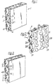
- a ducting panel 1 comprises a central core constituted by an openwork woven mesh 2 of high thermal conductivity strands e.g. copper, and plastics closure layers 4A, 4B located at opposed sides of the mesh 2 with the nodes 5 of the mesh warp 2 embedded in the plastics layers 4A, 4B to bond the layers to the mesh.
- a central duct 6 is formed between the layers 4A, 4B with the mesh warp 2A extending longitudinally in this duct.
- At least one of the layers i.e. layer 4A exposed to the sunlight is highly absorbent to radiant energy. In operation, the highly absorbent layer 4A picks up heat energy of the sun rays.
- the layer 4A exposed to the sunlight comprises a transparent or translucent plastics layer
- the other closure layer 4B comprises a double- layer 7/8 one layer 7 of which is a heat absorbent layer adjacent the mesh 2 covered by an outer insulating layer 8.
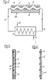
- Fig. 4 shows the fluid heating circuit of the solar energy system: this circuit includes a recirculation line 9, 10 for the flow of heat exchange fluid between a heat exchanger 11 and the duct 6 of panel 1.
- This recirculating fluid serves to heat a secondary fluid in the heat exchanger 11 which is supplied and discharged via lines 12 and 13 respectively.
- the ducting panel 1 of Figs. 3 (and 4) is particularly intended for use with a recirculating heat exchange liquid or fluid having a dark colour characteristic giving good heat absorbent properties.
- a particularly suitable heat exchange fluid of this type comprises a colloidal suspension of liquid (e.g. water) with fine carbon black particles: this may be referred to as "black water”.
- the mesh could be formed from a plain cross-laid array of strands (as shown in Figs. 5 and 6) with the interstices 14 of the mesh 2 secured for example by bonding.
- Fig. 5 the mesh 2 is embedded in a plastics core to form a matrix and plastics covering layers 4 cover the matrix as in Fig. 1, while in Fig. 6 the openwork of the mesh 2 is simply closed by a plastics filler layer 3 with the mesh presenting lateral projecting portions of good heat conducting property as in Fig. 2.
- a metal coating could be applied to the metal/plastics matrix.
- the present invention therefore provides a heat exchange panel or duct which will exhibit a very satisfactory heat exchange performance due to the high thermal conductivity mesh but which can be relatively inexpensive to manufacture since the bulk of the panel is made from less costly plastics material.
Landscapes
- Engineering & Computer Science (AREA)
- Thermal Sciences (AREA)
- General Engineering & Computer Science (AREA)
- Physics & Mathematics (AREA)
- Mechanical Engineering (AREA)
- Chemical & Material Sciences (AREA)
- Life Sciences & Earth Sciences (AREA)
- Sustainable Energy (AREA)
- Combustion & Propulsion (AREA)
- Sustainable Development (AREA)
- Dispersion Chemistry (AREA)
- Heat-Exchange Devices With Radiators And Conduit Assemblies (AREA)
- Laminated Bodies (AREA)
Applications Claiming Priority (2)
| Application Number | Priority Date | Filing Date | Title |
|---|---|---|---|
| GB3366277 | 1977-08-11 | ||
| GB33662/77A GB1572680A (en) | 1977-08-11 | 1977-08-11 | Heat transfer elements |
Publications (2)
| Publication Number | Publication Date |
|---|---|
| EP0000992A1 EP0000992A1 (en) | 1979-03-07 |
| EP0000992B1 true EP0000992B1 (en) | 1982-03-10 |
Family
ID=10355813
Family Applications (1)
| Application Number | Title | Priority Date | Filing Date |
|---|---|---|---|
| EP78300274A Expired EP0000992B1 (en) | 1977-08-11 | 1978-08-10 | Heat transfer elements and method for the manufacture of such elements |
Country Status (6)
| Country | Link |
|---|---|
| US (1) | US4403653A (enExample) |
| EP (1) | EP0000992B1 (enExample) |
| JP (1) | JPS5856070B2 (enExample) |
| CA (1) | CA1098113A (enExample) |
| DE (1) | DE2861658D1 (enExample) |
| GB (1) | GB1572680A (enExample) |
Families Citing this family (30)
| Publication number | Priority date | Publication date | Assignee | Title |
|---|---|---|---|---|
| GB1572680A (en) * | 1977-08-11 | 1980-07-30 | United Wire Group Ltd | Heat transfer elements |
| EP0029565A1 (de) * | 1979-11-24 | 1981-06-03 | Alfred Prof. Dr. Boettcher | Flexibler Sonnenkollektor |
| FR2508517A1 (fr) * | 1981-06-25 | 1982-12-31 | Seyve Daniel | Capteur panneau solaire formant un ensemble de plusieurs tuiles |
| IT1192543B (it) * | 1982-12-03 | 1988-04-20 | Tamara Pucci | Scambiatore di calore con lamine parallele ad elemento interposto a rete o simile,per rendere turbolento il moto del fluido |
| US4919200A (en) * | 1989-05-01 | 1990-04-24 | Stanislas Glomski | Heat exchanger wall assembly |
| US5338497A (en) * | 1992-04-03 | 1994-08-16 | Ford Motor Company | Induction heating method for forming composite articles |
| DE4406668C2 (de) * | 1993-04-27 | 1996-09-12 | Hewlett Packard Co | Verfahren und Vorrichtung zum Betreiben eines berührungsempfindlichen Anzeigegeräts |
| EP0719976B1 (en) * | 1993-09-03 | 1999-12-15 | Kabushiki Kaisha Sekuto Kagaku | Heat insulating board and heat insulating method using same |
| US6135968A (en) * | 1997-09-10 | 2000-10-24 | Scantek Medical, Inc. | Differential temperature measuring device and method |
| US6020049A (en) * | 1997-12-02 | 2000-02-01 | Cucinotta; Anthony J | Product for producing viaholes in reinforced laminates and the related method for manufacturing viaholes |
| US6107216A (en) * | 1997-12-12 | 2000-08-22 | Raytheon Company | Bonded structure with high-conductivity bonding element |
| US6086247A (en) * | 1998-02-05 | 2000-07-11 | Von Hollen; Dirk | Differential temperature sensor device for use in the detection of breast cancer and breast disease |
| FR2777984B1 (fr) * | 1998-04-22 | 2000-07-28 | Toutenkamion | Panneau solaire et dispositif de collecte d'energie solaire |
| US7744640B1 (en) * | 1999-08-11 | 2010-06-29 | Medical Products, Inc. | Thermal treatment garment and method of thermally treating body portions |
| DE10101650C1 (de) * | 2001-01-16 | 2002-08-29 | Daimler Chrysler Ag | Verstärktes Strukturelement |
| US6500529B1 (en) * | 2001-09-14 | 2002-12-31 | Tonoga, Ltd. | Low signal loss bonding ply for multilayer circuit boards |
| US6783841B2 (en) | 2001-09-14 | 2004-08-31 | Tonoga, Inc. | Low signal loss bonding ply for multilayer circuit boards |
| US7390317B2 (en) * | 2002-12-02 | 2008-06-24 | Applied Medical Resources Corporation | Universal access seal |
| US20050061473A1 (en) * | 2003-09-22 | 2005-03-24 | Coolhead Technologies, Inc. | Flexible heat exchangers |
| NL1027640C2 (nl) * | 2004-12-01 | 2006-06-02 | Stichting Energie | Warmtewisselaarelement, warmtewisselaar en werkwijze voor het wisselen van warmte. |
| WO2006110382A2 (en) | 2005-03-31 | 2006-10-19 | American Superconductor Corporation | Mesh-type stabilizer for filamentary coated superconductors |
| DE102006022629A1 (de) * | 2006-05-12 | 2007-11-15 | Spörl KG | Wärmetauschvorrichtung für einen Wärmeaustausch zwischen Medien und Webstruktur |
| JPWO2008069275A1 (ja) * | 2006-12-07 | 2010-03-25 | 日本電気株式会社 | 配線板およびその製造方法 |
| US7361100B1 (en) | 2006-12-20 | 2008-04-22 | Karsten Manufacturing Corporation | Metal composite golf club head |
| US7956278B1 (en) * | 2007-03-15 | 2011-06-07 | Onscreen Technologies, Inc. | Solar heat transfer apparatus |
| US20140231327A1 (en) * | 2013-02-15 | 2014-08-21 | Research Foundation Of The City University Of New York | Portable solar apparatus for purifying water |
| US10150049B2 (en) | 2014-12-15 | 2018-12-11 | Research Foundation Of The City University Of New York | Solar powered water purification device with cylindrical structure |
| US10150050B2 (en) | 2014-12-15 | 2018-12-11 | Research Foundation Of The City University Of New York | Solar powered water purification device with cylindrical structure |
| EP3264059B1 (en) * | 2016-06-27 | 2019-01-30 | MEAS France | Temperature sensor with heat transfer element and fabrication method |
| JP7296207B2 (ja) * | 2018-12-20 | 2023-06-22 | 三菱重工業株式会社 | 板状化学蓄熱体 |
Family Cites Families (17)
| Publication number | Priority date | Publication date | Assignee | Title |
|---|---|---|---|---|
| US902812A (en) * | 1908-03-27 | 1908-11-03 | Adolph Goetz | Process of pasteurization. |
| US1803764A (en) * | 1929-02-16 | 1931-05-05 | Ernest E Miller | Vehicle radiator |
| GB656811A (en) * | 1947-10-27 | 1951-09-05 | Bata | Improvements in or relating to radiators for heating buildings |
| US3236294A (en) * | 1961-11-09 | 1966-02-22 | Harry E Thomason | Basementless solar home |
| GB1170636A (en) * | 1966-05-10 | 1969-11-12 | Zanussi A Spa Industrie | Improvements in Evaporators for Refrigerators |
| US3825063A (en) * | 1970-01-16 | 1974-07-23 | K Cowans | Heat exchanger and method for making the same |
| GB1302516A (enExample) * | 1970-01-30 | 1973-01-10 | ||
| JPS5022365Y2 (enExample) * | 1971-07-20 | 1975-07-05 | ||
| JPS51131757U (enExample) * | 1975-04-16 | 1976-10-23 | ||
| US4072142A (en) * | 1975-09-02 | 1978-02-07 | Solaron Corporation | Heat absorber for solar energy |
| US4065592A (en) * | 1976-04-14 | 1977-12-27 | Hercules Incorporated | Solar energy absorber |
| US4230175A (en) * | 1977-02-15 | 1980-10-28 | Hoechst Aktiengesellschaft | Heat exchanger element |
| US4154224A (en) * | 1977-03-18 | 1979-05-15 | Ferriera Cress R | Solar steam generator |
| GB1572680A (en) * | 1977-08-11 | 1980-07-30 | United Wire Group Ltd | Heat transfer elements |
| US4203421A (en) * | 1977-09-08 | 1980-05-20 | Bencic David M | Solar heat collector |
| DE2862149D1 (en) * | 1978-08-10 | 1983-02-17 | Maxwell Wingate Davidson | Heat transfer elements and method for the manufacture of such elements |
| JPS55121395A (en) * | 1979-03-13 | 1980-09-18 | Matsushita Refrig Co | Heat conductive sealer |
-
1977
- 1977-08-11 GB GB33662/77A patent/GB1572680A/en not_active Expired
-
1978
- 1978-08-10 CA CA309,100A patent/CA1098113A/en not_active Expired
- 1978-08-10 DE DE7878300274T patent/DE2861658D1/de not_active Expired
- 1978-08-10 EP EP78300274A patent/EP0000992B1/en not_active Expired
- 1978-08-11 JP JP53097440A patent/JPS5856070B2/ja not_active Expired
-
1980
- 1980-04-23 US US06/143,840 patent/US4403653A/en not_active Expired - Lifetime
Also Published As
| Publication number | Publication date |
|---|---|
| EP0000992A1 (en) | 1979-03-07 |
| JPS5856070B2 (ja) | 1983-12-13 |
| JPS5452358A (en) | 1979-04-24 |
| GB1572680A (en) | 1980-07-30 |
| DE2861658D1 (en) | 1982-04-08 |
| US4403653A (en) | 1983-09-13 |
| US4403653B1 (enExample) | 1985-12-17 |
| CA1098113A (en) | 1981-03-24 |
Similar Documents
| Publication | Publication Date | Title |
|---|---|---|
| EP0000992B1 (en) | Heat transfer elements and method for the manufacture of such elements | |
| Chiou et al. | A slit-and-expanded aluminum-foil matrix solar collector | |
| DE2601976A1 (de) | Solar-plattensammler | |
| GB1583226A (en) | Heat exchanger and metal panel for same | |
| CA1088920A (en) | Heat exchanger element | |
| DE2714901A1 (de) | Waermeaustauscherelement | |
| DE102009017200B4 (de) | Temperiervorrichtung mit wenigstens einem Wärmeaustauscher | |
| DE19726330C2 (de) | Vakuum-Isolationspaneel, Verfahren zur Herstellung eines solchen Paneels und ein Verfahren zur Regelung der Wärmeströme | |
| DE3643668C2 (enExample) | ||
| US4261333A (en) | Solar heat exchanger | |
| DE69316856T2 (de) | Sonnenwärmezelle | |
| DE19505857C2 (de) | Sonnenkollektorelement | |
| US4060071A (en) | Solar collector for solar heating systems | |
| IL145426A (en) | Electrical water heating device with large contact surface | |
| US5724479A (en) | Fluid flow controlling member | |
| GB1562412A (en) | Means for collecting heat and solar energy for a house | |
| DE9208888U1 (de) | Wärmetauschelement | |
| KR100938910B1 (ko) | 태양에너지 집열판 | |
| CH654650A5 (en) | Solar collector for heating a heat-transfer medium | |
| DE19947730C1 (de) | Wärmetauschereinheit sowie Verfahren zur Herstellung einer Wärmetauschereinheit | |
| DE3119904A1 (de) | Waermetauscher-vorrichtung in gekruemmter form fuer solarheizung und -klimatisierung von raeumlichkeiten | |
| EP0007929B1 (en) | Heat transfer elements and method for the manufacture of such elements | |
| KR200299666Y1 (ko) | 태양에너지 집열판 | |
| DE19925245C2 (de) | Absorber für den Einsatz in thermischen Solarkollektoren | |
| EP0070981A1 (de) | Anlage und Kollektor zur Wärmegewinnung |
Legal Events
| Date | Code | Title | Description |
|---|---|---|---|
| PUAI | Public reference made under article 153(3) epc to a published international application that has entered the european phase |
Free format text: ORIGINAL CODE: 0009012 |
|
| AK | Designated contracting states |
Designated state(s): BE CH DE FR LU NL SE |
|
| 17P | Request for examination filed | ||
| GRAA | (expected) grant |
Free format text: ORIGINAL CODE: 0009210 |
|
| AK | Designated contracting states |
Designated state(s): BE CH DE FR LU NL SE |
|
| REF | Corresponds to: |
Ref document number: 2861658 Country of ref document: DE Date of ref document: 19820408 |
|
| RAP2 | Party data changed (patent owner data changed or rights of a patent transferred) |
Owner name: UNITED WIRE GROUP PUBLIC LIMITED COMPANY |
|
| PG25 | Lapsed in a contracting state [announced via postgrant information from national office to epo] |
Ref country code: BE Effective date: 19820810 |
|
| PG25 | Lapsed in a contracting state [announced via postgrant information from national office to epo] |
Ref country code: SE Effective date: 19820811 |
|
| PG25 | Lapsed in a contracting state [announced via postgrant information from national office to epo] |
Ref country code: LU Free format text: LAPSE BECAUSE OF NON-PAYMENT OF DUE FEES Effective date: 19820831 |
|
| REG | Reference to a national code |
Ref country code: CH Ref legal event code: PFA Free format text: UNITED WIRE GROUP P.L.C. |
|
| PG25 | Lapsed in a contracting state [announced via postgrant information from national office to epo] |
Ref country code: NL Effective date: 19830301 |
|
| NLV4 | Nl: lapsed or anulled due to non-payment of the annual fee | ||
| REG | Reference to a national code |
Ref country code: FR Ref legal event code: TP |
|
| REG | Reference to a national code |
Ref country code: CH Ref legal event code: PUE Owner name: GLYNWED PLASTICS LIMITED Ref country code: CH Ref legal event code: PFA Free format text: UNITED WIRE GROUP LIMITED |
|
| EUG | Se: european patent has lapsed |
Ref document number: 78300274.4 Effective date: 19850611 |
|
| PGFP | Annual fee paid to national office [announced via postgrant information from national office to epo] |
Ref country code: CH Payment date: 19970808 Year of fee payment: 20 |
|
| PGFP | Annual fee paid to national office [announced via postgrant information from national office to epo] |
Ref country code: FR Payment date: 19970812 Year of fee payment: 20 |
|
| PGFP | Annual fee paid to national office [announced via postgrant information from national office to epo] |
Ref country code: DE Payment date: 19971020 Year of fee payment: 20 |
|
| PG25 | Lapsed in a contracting state [announced via postgrant information from national office to epo] |
Ref country code: CH Free format text: LAPSE BECAUSE OF EXPIRATION OF PROTECTION Effective date: 19980809 |
|
| REG | Reference to a national code |
Ref country code: CH Ref legal event code: PL |
|
| PLBE | No opposition filed within time limit |
Free format text: ORIGINAL CODE: 0009261 |
|
| STAA | Information on the status of an ep patent application or granted ep patent |
Free format text: STATUS: NO OPPOSITION FILED WITHIN TIME LIMIT |