DE60101388T2 - RF HOME AUTOMATION SYSTEM WITH VARIABLE CONTROLLERS - Google Patents
RF HOME AUTOMATION SYSTEM WITH VARIABLE CONTROLLERS Download PDFInfo
- Publication number
- DE60101388T2 DE60101388T2 DE60101388T DE60101388T DE60101388T2 DE 60101388 T2 DE60101388 T2 DE 60101388T2 DE 60101388 T DE60101388 T DE 60101388T DE 60101388 T DE60101388 T DE 60101388T DE 60101388 T2 DE60101388 T2 DE 60101388T2
- Authority
- DE
- Germany
- Prior art keywords
- controller
- devices
- memory
- identifiers
- identifier
- Prior art date
- Legal status (The legal status is an assumption and is not a legal conclusion. Google has not performed a legal analysis and makes no representation as to the accuracy of the status listed.)
- Expired - Lifetime
Links
Classifications
-
- G—PHYSICS
- G05—CONTROLLING; REGULATING
- G05B—CONTROL OR REGULATING SYSTEMS IN GENERAL; FUNCTIONAL ELEMENTS OF SUCH SYSTEMS; MONITORING OR TESTING ARRANGEMENTS FOR SUCH SYSTEMS OR ELEMENTS
- G05B15/00—Systems controlled by a computer
- G05B15/02—Systems controlled by a computer electric
-
- G—PHYSICS
- G05—CONTROLLING; REGULATING
- G05B—CONTROL OR REGULATING SYSTEMS IN GENERAL; FUNCTIONAL ELEMENTS OF SUCH SYSTEMS; MONITORING OR TESTING ARRANGEMENTS FOR SUCH SYSTEMS OR ELEMENTS
- G05B19/00—Programme-control systems
- G05B19/02—Programme-control systems electric
- G05B19/04—Programme control other than numerical control, i.e. in sequence controllers or logic controllers
- G05B19/042—Programme control other than numerical control, i.e. in sequence controllers or logic controllers using digital processors
- G05B19/0426—Programming the control sequence
-
- H—ELECTRICITY
- H04—ELECTRIC COMMUNICATION TECHNIQUE
- H04B—TRANSMISSION
- H04B7/00—Radio transmission systems, i.e. using radiation field
- H04B7/14—Relay systems
- H04B7/15—Active relay systems
- H04B7/155—Ground-based stations
- H04B7/15507—Relay station based processing for cell extension or control of coverage area
-
- G—PHYSICS
- G05—CONTROLLING; REGULATING
- G05B—CONTROL OR REGULATING SYSTEMS IN GENERAL; FUNCTIONAL ELEMENTS OF SUCH SYSTEMS; MONITORING OR TESTING ARRANGEMENTS FOR SUCH SYSTEMS OR ELEMENTS
- G05B2219/00—Program-control systems
- G05B2219/20—Pc systems
- G05B2219/21—Pc I-O input output
- G05B2219/21042—Address a group, a zone
-
- G—PHYSICS
- G05—CONTROLLING; REGULATING
- G05B—CONTROL OR REGULATING SYSTEMS IN GENERAL; FUNCTIONAL ELEMENTS OF SUCH SYSTEMS; MONITORING OR TESTING ARRANGEMENTS FOR SUCH SYSTEMS OR ELEMENTS
- G05B2219/00—Program-control systems
- G05B2219/20—Pc systems
- G05B2219/21—Pc I-O input output
- G05B2219/21073—Each module has push button, trigger circuit to initialise address setting
-
- G—PHYSICS
- G05—CONTROLLING; REGULATING
- G05B—CONTROL OR REGULATING SYSTEMS IN GENERAL; FUNCTIONAL ELEMENTS OF SUCH SYSTEMS; MONITORING OR TESTING ARRANGEMENTS FOR SUCH SYSTEMS OR ELEMENTS
- G05B2219/00—Program-control systems
- G05B2219/20—Pc systems
- G05B2219/25—Pc structure of the system
- G05B2219/25081—Clone, copy configuration from first device, in teach mode, to second identical device
-
- G—PHYSICS
- G05—CONTROLLING; REGULATING
- G05B—CONTROL OR REGULATING SYSTEMS IN GENERAL; FUNCTIONAL ELEMENTS OF SUCH SYSTEMS; MONITORING OR TESTING ARRANGEMENTS FOR SUCH SYSTEMS OR ELEMENTS
- G05B2219/00—Program-control systems
- G05B2219/20—Pc systems
- G05B2219/25—Pc structure of the system
- G05B2219/25181—Repeater
-
- G—PHYSICS
- G05—CONTROLLING; REGULATING
- G05B—CONTROL OR REGULATING SYSTEMS IN GENERAL; FUNCTIONAL ELEMENTS OF SUCH SYSTEMS; MONITORING OR TESTING ARRANGEMENTS FOR SUCH SYSTEMS OR ELEMENTS
- G05B2219/00—Program-control systems
- G05B2219/20—Pc systems
- G05B2219/25—Pc structure of the system
- G05B2219/25196—Radio link, transponder
-
- G—PHYSICS
- G05—CONTROLLING; REGULATING
- G05B—CONTROL OR REGULATING SYSTEMS IN GENERAL; FUNCTIONAL ELEMENTS OF SUCH SYSTEMS; MONITORING OR TESTING ARRANGEMENTS FOR SUCH SYSTEMS OR ELEMENTS
- G05B2219/00—Program-control systems
- G05B2219/20—Pc systems
- G05B2219/25—Pc structure of the system
- G05B2219/25208—Control message, address and command portion
-
- G—PHYSICS
- G05—CONTROLLING; REGULATING
- G05B—CONTROL OR REGULATING SYSTEMS IN GENERAL; FUNCTIONAL ELEMENTS OF SUCH SYSTEMS; MONITORING OR TESTING ARRANGEMENTS FOR SUCH SYSTEMS OR ELEMENTS
- G05B2219/00—Program-control systems
- G05B2219/20—Pc systems
- G05B2219/25—Pc structure of the system
- G05B2219/25211—Broadcast mode, length message, command, address of originator and destination
-
- G—PHYSICS
- G05—CONTROLLING; REGULATING
- G05B—CONTROL OR REGULATING SYSTEMS IN GENERAL; FUNCTIONAL ELEMENTS OF SUCH SYSTEMS; MONITORING OR TESTING ARRANGEMENTS FOR SUCH SYSTEMS OR ELEMENTS
- G05B2219/00—Program-control systems
- G05B2219/20—Pc systems
- G05B2219/26—Pc applications
- G05B2219/2642—Domotique, domestic, home control, automation, smart house
-
- G—PHYSICS
- G05—CONTROLLING; REGULATING
- G05B—CONTROL OR REGULATING SYSTEMS IN GENERAL; FUNCTIONAL ELEMENTS OF SUCH SYSTEMS; MONITORING OR TESTING ARRANGEMENTS FOR SUCH SYSTEMS OR ELEMENTS
- G05B2219/00—Program-control systems
- G05B2219/30—Nc systems
- G05B2219/32—Operator till task planning
- G05B2219/32234—Maintenance planning
-
- G—PHYSICS
- G05—CONTROLLING; REGULATING
- G05B—CONTROL OR REGULATING SYSTEMS IN GENERAL; FUNCTIONAL ELEMENTS OF SUCH SYSTEMS; MONITORING OR TESTING ARRANGEMENTS FOR SUCH SYSTEMS OR ELEMENTS
- G05B2219/00—Program-control systems
- G05B2219/30—Nc systems
- G05B2219/37—Measurements
- G05B2219/37252—Life of tool, service life, decay, wear estimation
Landscapes
- Engineering & Computer Science (AREA)
- Physics & Mathematics (AREA)
- General Physics & Mathematics (AREA)
- Automation & Control Theory (AREA)
- General Engineering & Computer Science (AREA)
- Computer Networks & Wireless Communication (AREA)
- Signal Processing (AREA)
- Selective Calling Equipment (AREA)
- Mobile Radio Communication Systems (AREA)
- Automatic Analysis And Handling Materials Therefor (AREA)
- Control And Other Processes For Unpacking Of Materials (AREA)
- Printers Or Recording Devices Using Electromagnetic And Radiation Means (AREA)
- Pinball Game Machines (AREA)
- Slot Machines And Peripheral Devices (AREA)
- Safety Devices In Control Systems (AREA)
- Mounting Of Printed Circuit Boards And The Like (AREA)
Abstract
Description
Fachgebiet der ErfindungField of the Invention
Die vorliegende Erfindung betrifft ein drahtloses Hausautomatisierungssystem mit einer Steuerung zum Steuern einer breiten Vielfalt an Funktionen. über eine Zwei-Richtungs-Kommunikation mit mehreren Vorrichtungen. Insbesondere betrifft die Erfindung Systeme mit zwei oder mehr Steuerungen zum Steuern von Vorrichtungen, wobei das System betreffende Informationen von beiden Steuerungen gemeinsam genutzt werden können.The present invention relates to a wireless home automation system with a controller for Control a wide variety of functions. via two-way communication with several devices. In particular, the invention relates to systems with two or more controllers for controlling devices, wherein information regarding the system shared by both controllers can be used.
Hintergrund der Erfindungbackground the invention
Hausautomatisierungssysteme zur Steuerung von Vorrichtungen mit verschiedenen Funktionen, wie etwa Beleuchtungs- und Audioanlagen in einem Gebäude haben sich in Richtung eines „Smart-Home"-Konzepts entwickelt, in dem verschiedene Eingabe-Ausgabe- (E/A-) Vorrichtungen mit einem breiten Bereich an Funktionen durch eine zentrale Steuerung ferngesteuert werden. Derartige Systeme sind als Netzwerke mit mehreren Knoten aufgebaut, welche Steuerungen, E/A-Vorrichtungen oder dedizierte Signal-Repeater oder Verstärker sein können.Home automation systems for control of devices with various functions, such as lighting and audio systems in a building have evolved towards a "smart home" concept in which various input-output (I / O) devices with a wide range of functions a central controller can be controlled remotely. Such systems are built as networks with several nodes, which controls, I / O devices or dedicated signal repeaters or amplifiers can.
Die Qualität derartiger Systeme ist typischerweise durch eine Anzahl von Parametern definiert:
- – Zuverlässigkeit. Wie oft ist ein von dem beabsichtigten Empfänger empfangenes Signal fehlerhaft oder wird gar nicht empfangen. Die Zuverlässigkeit kann in einer Anzahl von Arten, wie etwa als MTBF-Zeitwert oder Bitfehlerrate, quantifiziert werden, und viele Fehlerarten können von dem System automatisch erkannt und korrigiert werden. Zuverlässigkeit als ein Qualitätsparameter wird am besten damit beschrieben, ob der Benutzer regelmäßig erlebt, daß das System die gewünschte Aufgabe nicht erfüllt.
- – Reichweite/Abdeckung. Wie groß ist ein Netzwerk, das von dem System unterstützt werden kann und gibt es eine notwendige minimale Dichte an Signal-Repeatern oder Verstärkern. Kann auch ein Knoten mit dem Netzwerk verbunden werden, um überall in der Reichweite des Netzwerks Signale zu senden und zu empfangen, oder gibt es irgendwelche „Empfangslöcher".
- – Vielseitigkeit. Welche Arten von E/A-Vorrichtungen und Funktionen können von dem System gesteuert werden, und kann das Netzwerk die notwendigen Signale, die für diese Anwendungen verwendet werden, unterstützen. Kann die Netzwerktopologie auf neue Funktionalitäten ohne übermäßige Last erweitert werden und unterstützt das System/Netzwerk eine große Anzahl von Knoten. Diese Überlegungen stehen oft in Bezug zu einem Kommunikationsprotokoll des Systems und hängen davon ab, ob das Kommunikationsprotokoll mit Gedanken an eine bestimmte Anwendung oder auf eine bestimmte Art von E/A-Vorrichtung optimiert gestaltet ist.
- – Flexibilität. Das System sollte einfach zu installieren, zu konfigurieren, zu ändern und zu benutzen sein. Somit sollte der Lernvorgang für neue Knoten und das Konfigurieren neuer Leitwege für die Signalübertragung zumindest in gewissem Maße automatisiert sein. Auch sollte das Programmieren und die Verwendung von Funktionen, ebenso wie die Ausdehnung des Systems eine einfache und überschaubare Aufgabe für den Benutzer sein. Dies gilt umso mehr in Hausautomatisierungssystemen für die Verwendung in Privathäusern.
- - reliability. How often is a signal received by the intended receiver incorrect or not received at all. Reliability can be quantified in a number of ways, such as MTBF time or bit error rate, and many kinds of errors can be automatically detected and corrected by the system. Reliability, as a quality parameter, is best described as whether the user regularly experiences that the system is not performing the desired task.
- - Range / coverage. How big is a network that can be supported by the system and is there a necessary minimum density of signal repeaters or amplifiers. Can a node also be connected to the network to send and receive signals anywhere in the network range, or are there any "receive holes".
- - versatility. What types of I / O devices and functions can be controlled by the system and the network can support the necessary signals used for these applications. Can the network topology be expanded to new functionalities without excessive load and the system / network supports a large number of nodes. These considerations are often related to a communication protocol of the system and depend on whether the communication protocol is optimized for a specific application or for a specific type of I / O device.
- - flexibility. The system should be easy to install, configure, change, and use. Thus, the learning process for new nodes and the configuration of new routes for signal transmission should be at least to some extent automated. Programming and using functions, as well as expanding the system, should also be a simple and manageable task for the user. This is all the more true in home automation systems for use in private homes.
Automatisierungssysteme auf der Basis festverdrahteter Netzwerke stellen bei den ersten drei Qualitätsparametern und sehr selten bei dem vierten Parameter eine hohe Qualität zur Verfügung und sind oft die erste Wahl bei Systemen mit hoher Kapazität und hoher Sicherheit, wenn eine hohe Qualität erforderlich ist. Jedoch haben festverdrahtete Netzwerke eine Anzahl offensichtlicher Nachteile:
- – Abhängigkeit vom Medium. Die Unterbrechung eines wichtigen Leitungsabschnitts kann das gesamte Netzwerk blockieren.
- – Geringe Flexibilität. Festverdrahtete Netzwerke sind sehr unflexibel, wenn ein Knoten an einer Position außerhalb des vorhandenen Netzwerks oder an einer mit Draht verbundenen Position innerhalb des Netzwerkes gewünscht wird, muß ein neuer Leitungszweig gezogen und mit dem Netzwerk verbunden werden.
- – Installation. Die Erstinstallation des Netzwerks, das Ziehen und Verbinden von Leitungen ebenso wie die Erweiterung eines vorhandenen Netzwerks sind aufwendig und erfordern häufig die Unterstützung von Fachleuten.
- – Preis. Die Kosten im Zusammenhang mit der Installation und der Erweitung von festverdrahteten Netzwerken sind extrem hoch. Wenn ein festverdrahtetes Netz für ein Automatisierungssystem in einem Einfamilienhaus installiert werden soll, summieren sich die Ausgaben, um die Leitungen legen und anschließen zu lassen, auf 10.000 US-Dollar, wenn es während des Hausbaus installiert wird und auf 25.000 US-Dollar, wenn es in einem vorhandenen Haus installiert werden soll. Dazu kommt obendrein der Preis für Steuerungen, E/A-Vorrichtungen und Signal-Repeater oder Verstärker.
- - Dependence on the medium. The interruption of an important line section can block the entire network.
- - Low flexibility. Hardwired networks are very inflexible, if a node is desired at a position outside the existing network or at a position connected by wire within the network, a new line branch must be drawn and connected to the network.
- - installation. The initial installation of the network, the pulling and connecting of lines as well as the expansion of an existing network are complex and often require the support of experts.
- - price. The costs associated with installing and expanding hardwired networks are extremely high. If a hard-wired network for an automation system is to be installed in a family home, the cost of installing and connecting the cables will add up to $ 10,000 if it is installed during home construction and $ 25,000 if it is installed to be installed in an existing house. In addition, there is the price for controls, I / O devices and signal repeaters or amplifiers.
Obwohl festverdrahtete Netzwerke im allgemeinen eine bessere Qualität zur Verfügung stellen, werden drahtlose Netzwerke immer beliebter als eine günstige und leicht erreichbare Netzlösung. Drahtlose Netzwerke überwinden die weiter oben erwähnten Nachteile von festverdrahteten Netzwerken deutlich. Die meisten vorhandenen drahtlosen Billig-Automatisierungssysteme haben jedoch bezüglich der meisten der vorher erwähnten Parameter eine niedrige Qualität. Drahtlose Automatisierungssysteme mit höherer Bandbreite sind typischerweise sehr komplex und erfordern eine höhere Verarbeitungsleistung, wodurch der Preis nahe an den Preis für ein festverdrahtetes Netzwerk kommt.Although hardwired networks generally provide better quality wireless Networks are becoming more popular than a cheap and easily accessible one Network solution. Overcome wireless networks those mentioned above Disadvantages of hardwired networks clearly. Most have existing wireless cheap automation systems, however in terms of most of the previously mentioned Low quality parameters. Wireless automation systems with higher bandwidth are typical very complex and require higher processing power, making the price close to the price of a hard-wired network comes.
US-A-5 905 442 offenbart ein drahtloses Automatisierungssystem mit einer zentralisierten Fernsteuerung, die E/A-Vorrichtungen zur Versorgung von Geräten mit elektrischem Strom aus Steckdosen des Stromleitungsnetzes im Gebäude steuert. Die Fernsteuerung und die E/A-Vorrichtungen weisen HF-Transceiver auf, und das System enthält dedizierte Repeatereinheiten zum Wiederholen von Signalen für die E/A-Vorrichtungen außerhalb der Reichweite der Fernsteuerung.US-A-5 905 442 discloses a wireless Automation system with centralized remote control, the I / O devices to supply devices with electrical current from sockets in the power line network in building controls. The remote control and I / O devices have RF transceivers on, and the system contains dedicated repeater units for repeating signals for the I / O devices outside the range of the remote control.
US-A-5 875 179 beschreibt ein Verfahren zum Synchronisieren von Kommunikationen über eine Backbone-Architektur in einem drahtlosen Netzwerk. Das System ruft zwei Steuerungen auf, von denen eine ein Hauptrechner und die andere ein alternativer Hauptrechner ist, der nur dann aktiviert wird, wenn der Hauptrechner nicht arbeitet. Dedizierte Repeater und E/A-Vorrichtungen in dem System werden gemeinsam als Knoten bezeichnet, jedoch ist aus dem Zusammenhang klar, daß es einen deutlichen funktionalen Unterschied zwischen Repeaterknoten und End- (E/A-) Knoten gibt.US-A-5 875 179 describes a method to synchronize communications over a backbone architecture in a wireless network. The system calls two controls, one of which is a host and the other an alternative Is the main computer, which is only activated when the main computer not working. Dedicated repeaters and I / O devices in the system become common referred to as a knot, but it is clear from the context that there is a clear functional difference between repeater nodes and End (I / O) nodes there.
US-A-4 427 968 offenbart ein drahtloses Automatisierungssystem mit flexibler Leitweglenkung. Eine zentrale Station erzeugt ein Signal für eine E/A-Vorrichtung, das Signal enthält einen Leitwegkode, einen Adreßcode, einen Kennungskode und einen Nachrichtenkode. Dedizierte Repeater in der Architektur empfangen die Signale und folgen einem spezifizierten Verfahren zum Wiederholen des Signals. Repeater können auch als Endknoten adressiert werden, z. B. damit die Steuerung Leitwegtabellen herunterladen kann.US-A-4 427 968 discloses a wireless Automation system with flexible routing. A central one Station generates a signal for an I / O device, the signal contains a routing code, an address code, a ID code and a message code. Dedicated repeaters in the Architecture receive the signals and follow a specified one Procedure for repeating the signal. Repeaters can too are addressed as end nodes, e.g. B. the control routing tables can download.
Zusammenfassung der ErfindungSummary the invention
Die vorliegende Erfindung stellt ein qualitativ hochwertiges, günstiges Automatisierungssystem unter Verwendung von Hochfrequenz- (HF-) Signalen zur Verfügung. Um den Preis zu verringern, arbeitet das System gemäß der vorliegenden Erfindung bevorzugt bei einer Bandbreite, die für Steuerungsbefehle reserviert ist, d. h. eine Bandbreite um 10 kb/s. Eine derartig niedrige Bandbreite berücksichtigt, daß die Chips zu niedrigeren Preisen massengefertigt werden können als Chips für Systeme mit großer Bandbreite. Auch arbeiten HF-Sender und Empfänger des Systems bevorzugt innerhalb eines „öffentlichen" Frequenzbereichs, in dem keine Lizenz erforderlich ist, wodurch die Kosten weiter verringert werden.The present invention provides a high quality, affordable Automation system using radio frequency (HF) Signals available. To reduce the price, the system works according to the present one In the case of a bandwidth which is reserved for control commands, the invention preferably d. H. a bandwidth around 10 kb / s. Such a low bandwidth considered, that the Chips can be mass-produced at lower prices than Chips for Systems with large Bandwidth. The system's RF transmitter and receiver also work preferentially within a "public" frequency range, in which no license is required, which further increases the cost be reduced.
Das Wählen eines Betriebs mit geringer Bandbreite in einem öffentlichen Frequenzbereich bringt jedoch eine Anzahl von Problemen ein, welche die Qualität des Systems verringern können:
- – Eine niedrige Bandbreite ergibt eine niedrige Kapazität für die Datenmenge, die in Signalen enthalten sein kann.
- – Eine große Anzahl von Vorrichtungen arbeiten im öffentlichen Frequenzbereich, was zu einem großen Maß an Hochfrequenzinterferenz führt.
- – Die erlaubte Sendeleistung von HF-Sendern ist be grenzt, was zu einer begrenzten Signalreichweite führt.
- - A low bandwidth results in a low capacity for the amount of data that can be contained in signals.
- - A large number of devices operate in the public frequency range, resulting in a large amount of radio frequency interference.
- - The permitted transmission power of RF transmitters is limited, which leads to a limited signal range.
Um diese Probleme zu überwinden, ist das System gemäß der vorliegenden Erfindung optimiert, um eine hohe Zuverlässigkeit, Reichweite/Abdeckung, Vielseitigkeit und Flexibilität sicherzustellen.To overcome these problems is the system according to the present Invention optimized for high reliability, range / coverage, Versatility and flexibility sure.
Somit ist es eine Aufgabe der vorliegenden Erfindung, ein drahtloses Hausautomatisierungssystem zur Verfügung zu stellen, in dem Informationen von Steuerungen in dem System gemeinsam genutzt werden, um so wenig Signale wie möglich und so kurze Signale wie möglich zu senden.It is therefore an object of the present Invention to provide a wireless home automation system put information shared by controls in the system be used to get as few signals as possible and as short signals as possible to send.
Es ist eine andere Aufgabe der vorliegenden Erfindung, ein drahtloses Hausautomatisierungssystem zur Verfügung zu stellen, das in einer Weise Informationen speichert und Funktionen ausführt, die besonders für HF-Hausautomatisierungssysteme mit niedriger Bandbreite geeignet ist, die in einem „öffentlichen" Frequenzbereich arbeiten.It is another object of the present Invention to provide a wireless home automation system that stores information and functions in a way executing, which especially for RF home automation systems with low bandwidth are suitable is in a "public" frequency range work.
Es ist eine weitere Aufgabe der vorliegenden Erfindung, ein drahtloses Hausautomatisierungssystem zum Steuern und Überwachen von Einrichtungen und Geräten zur Verfügung zu stellen, das eine Gesamtarchitektur und Programmierung aufweist, die eine einfache Konfigurierung, Synchronisation und Erweiterbarkeit ermöglicht, wenn mehr als eine Steuerung in dem System enthalten ist.It is another object of the present Invention, a wireless home automation system for control and monitor of facilities and equipment to disposal to provide that has an overall architecture and programming, which enables easy configuration, synchronization and expandability, if more than one controller is included in the system.
Es ist noch eine weitere Aufgabe der vorliegenden Erfindung, ein drahtloses Hausautomatisierungssystem zur Verfügung zu stellen, das Hochfrequenzsignale zum Steuern und Überwachen von Vorrichtungen und zum Vervielfältigen und Aktualisieren von Steuerungen in dem System verwendet.It is another task of the present invention, a wireless home automation system to disposal to provide the high frequency signals for control and monitoring of devices and for copying and updating Controls used in the system.
In einem ersten Aspekt stellt die
Erfindung ein Automatisierungssystem zum Steuern und Überwachen mehrerer
Vor richtungen unter Verwendung von Steuerungen zur Verfügung, wobei
jede von den mehreren Vorrichtungen aufweist:
einen Empfänger zum
Empfangen von Signalen,
einen Sender zum Senden von Signalen,
einen
ersten Speicher, welcher eine die Vorrichtung kennzeichnende Vorrichtungskennung
enthält,
einen
Prozessor zum Steuern des Empfangs und des Sendens von Signalen,
und
eine Einrichtung zum Liefern eines Ausgangssignals an,
oder zum Empfangen eines Eingangssignals von einem mit der Vorrichtung
verbundenen Gerät
als Antwort auf ein empfangenes Signal,
eine erste Steuerung,
die aufweist:
einen Hochfrequenzsender zum Senden von Signalen,
einen
Hochfrequenzempfänger
zum Empfangen von Signalen,
einen ersten Speicher, der eine
organisierte Datenstruktur aufweist, die Vorrichtungskennungen von
Vorrichtungen, die durch die erste Steuerung gesteuert werden, aufweist,
einen
zweiten Speicher, der eine die erste Steuerung kennzeichnende Steuerungskennung
ausfweist, und
einen Prozessor zum Steuern des Empfangs und
des Sendens von Signalen und welcher zum Speichern und Lesen von
Vorrichtungskennungen in dem ersten Speicher angepaßt ist,
wobei der Prozessor eine Einrichtung zum Erzeugen eines Signals
aufweist, das an eine oder mehrere Vorrichtungen adressiert ist
und Instruktionen bezüglich
des Betriebs des mit der Vorrichtung verbundenen Geräts aufweist,
eine
zweite Steuerung, die aufweist:
einen Hochfrequenzsender zum
Senden von Signalen,
einen Hochfrequenzempfänger zum Empfangen von Signalen,
einen
ersten Speicher, der in einer entsprechenden organisierten Datenstruktur
Vorrichtungskennungen von Vorrichtungen, die durch die zweite Steuerung
gesteuert werden, enthält,
einen
zweiten Speicher, der eine die zweite Steuerung kennzeichnende Steuerungskennung
aufweist, und
einen Prozessor zum Steuern bzw. Verwalten des
Empfangs und des Sendens von Signalen und welcher zum Speichern
und Lesen von Vorrichtungskennungen in dem ersten Speicher angepaßt ist,
wobei der Prozessor eine Einrichtung zum Erzeugen eines Signals
aufweist, das an eine oder mehrere Vorrichtungen adressiert ist und
Instruktionen bezüglich
des Betriebs des mit der Vorrichtung verbundenen Geräts aufweist,
wobei
der Prozessor der ersten Steuerung ferner eine Einrichtung zum Erzeugen
von einem oder mehreren Signalen, welche die Vorrichtungskennungen
aus der organisierten Datenstruktur des ersten Speichers der ersten
Steuerung aufweist, aufweist, und wobei der Prozessor der zweiten
Steuerung einen ersten normalen Betriebsmodus besitzt, in welchem
er dafür
angepaßt
ist, Signale an Vorrichtungen zu senden und Signale davon zu empfangen,
die von der zweiten Steuerung gesteuert werden, und einen zweiten
Betriebsmodus, in welchem er dafür
angepaßt
ist, das eine oder mehrere Signale aus der ersten Steuerung zu empfangen
und die Vorrichtungskennungen dementsprechend in der organisierten
Datenstruktur des ersten Speichers der zweiten Steuerung zu speichern.In a first aspect, the invention provides an automation system for controlling and monitoring multiple devices using controllers, each of the multiple devices comprising:
a receiver for receiving signals,
a transmitter for sending signals,
a first memory which contains a device identifier which characterizes the device,
a processor for controlling the reception and transmission of signals, and
means for supplying an output signal to or for receiving an input signal from a device connected to the device in response to a received signal,
a first controller, which has:
a radio frequency transmitter for sending signals,
a radio frequency receiver for receiving signals,
a first memory which has an organized data structure which has device identifiers of devices which are controlled by the first controller,
a second memory which identifies a control identifier identifying the first control, and
a processor for controlling the reception and transmission of signals and adapted to store and read device identifiers in the first memory, the processor comprising means for generating a signal addressed to one or more devices and instructions for operation of the device connected to the device,
a second controller, which has:
a radio frequency transmitter for sending signals,
a radio frequency receiver for receiving signals,
a first memory which contains, in a corresponding organized data structure, device identifiers of devices which are controlled by the second controller,
a second memory which has a control identifier which characterizes the second controller, and
a processor for controlling or managing the reception and transmission of signals and adapted to store and read device identifiers in the first memory, the processor comprising means for generating a signal addressed to one or more devices and instructions regarding the operation of the device connected to the device,
wherein the processor of the first controller further comprises means for generating one or more signals comprising the device identifiers from the organized data structure of the first memory of the first controller, and wherein the processor of the second controller has a first normal operating mode in which it is adapted to send and receive signals to devices controlled by the second controller and a second mode of operation in which it is adapted to receive the one or more signals from the first controller and the device identifiers accordingly store in the organized data structure of the first memory of the second controller.
Bevorzugt ist der Prozessor der zweiten Steuerung dafür angepaßt, in empfangenen Signalen enthaltene Daten zu speichern, indem er eine Einrichtung zum entsprechenden Speichern der empfangenen Daten in der organisierten Datenstruktur des ersten Speichers der zweiten Steuerung aufweist.The processor is preferably the second Control for it customized, store data contained in received signals by a device for storing the received data accordingly in the organized data structure of the first memory of the second Control.
Die organisierte Datenstruktur des ersten Speichers in der ersten und der zweiten Steuerung sind Datenstrukturen zum Speichern von Daten in Bezug auf den Betrieb des Systems, folglich können die ersten Speicher aufweisen: Bereiche, die reserviert sind, einzelne Vorrichtungskennungen zu enthalten, Bereiche, die reserviert sind, Gruppen von Vorrichtungskennungen zu enthalten, Bereiche, die reserviert sind, Einstellungen oder alphanumerische Daten zu enthalten, die einzelne oder Gruppen von Kennungen betreffen, etc. Die organisierten Datenstrukturen des ersten Speichers in der ersten und der zweiten Steuerung brauchen nicht identisch oder äquivalent sein, sondern müssen einander, was die Bereiche betrifft, die dafür bestimmt sind, bestimmte Datentypen zu enthalten, entsprechen.The organized data structure of the first memory in the first and the second controller are data structures for storing data related to the operation of the system, consequently can the first stores have: areas that are reserved, individual To contain device identifiers, areas that are reserved, Groups of device identifiers to contain areas that are reserved are to contain settings or alphanumeric data that relate to individuals or groups of identifiers, etc. The organized ones Data structures of the first memory in the first and the second Controls don't have to be identical or equivalent, they have to be mutually exclusive, as for the areas that are meant to be determined To contain data types correspond.
Von der zweiten Steuerung empfangene Daten werden dementsprechend gespeichert, wenn sie in einen Bereich gespeichert werden, der dafür reserviert ist, einen Datentyp zu speichern, der gleich dem Datentyp ist, für den der Bereich, aus dem die Daten gelesen wurden, reserviert ist.Received from the second controller Data is saved accordingly when it is in an area be saved for that is reserved to store a data type that is equal to the data type, for the the area from which the data was read is reserved.
In der vorliegenden Beschreibung und den Ansprüchen bezeichnet der Begriff „Prozessor" jeden herkömmlichen oder herstellerspezifischen Prozessor oder Mikroprozessor, wie etwa einen festverdrahteten herstellerspezifischen Prozessor oder einen endlichen Automaten, einen Nur-Lese-Speicher (ROM) oder einen mit Software programmierbaren Mikroprozessor ebenso wie Kombinationen daraus, die fähig sind, die erforderliche Verwaltung empfangener und gesendeter Daten zu bereitzustellen.In the present description and the claims the term "processor" means any conventional one or manufacturer-specific processor or microprocessor, such as a hardwired manufacturer specific processor or finite state machines, a read-only memory (ROM) or one with Software programmable microprocessor as well as combinations out of that capable are the required management of received and sent data to provide.
Der Begriff „Speicher" bezeichnet einen oder mehrere Speicherbereiche, die geeignet sind, digitale Informationen zu speichern. Bevorzugt ist es möglich, Daten in dem Speicher zu lesen, in ihn zu schreiben und aus ihm zu löschen. Der Speicher kann in einer größeren Speicherstruktur zugewiesen sein, die mehrere Speicher aufweist, die von einem Prozessor z. B. zum Speichern von Anwendungsprogrammen und/oder zur Datenspeicherung verwendet werden.The term “memory” denotes one or more memory areas, which are suitable for storing digital information. Prefers Is it possible, Read data in, write to and from memory to delete. The memory can be in a larger memory structure be allocated which has multiple memories allocated by a processor z. B. for storing application programs and / or for data storage be used.
Der Begriff „Signal" bezeichnet einen Informationsüberbringer, wie etwa eine Folge von elektromagnetischen (HF-) Strahlungsimpulsen. Bevorzugt wird das Signal durch eine Modulation einer Trägerwellenform gebildet und durch eine Demodulation während des Empfangs wiedergewonnen. Die Modulationen können digitale Modulationen sein, um digitale Informationen zu transportieren. Die Information in einem Signal ist gemäß der vorliegenden Erfindung bevorzugt in einem digitalen Kommunikationsrahmen enthalten, der eine Anzahl den Rahmen kennzeichnender Bits und eine Anzahl von Bits aufweist, welche die übertragenen Informationen oder Daten transportieren.The term "signal" denotes an information carrier, such as a sequence of electromagnetic (RF) radiation pulses. The signal is preferred by modulating a carrier waveform formed and recovered by demodulation during reception. The modulations can be digital modulations to carry digital information. According to the present invention, the information in a signal is preferably contained in a digital communication frame which has a number of bits identifying the frame and a number of bits which carry the transmitted information or data.
Eine Kennung ist eine Datenzeichenfolge, die eine Steuerung oder eine Vorrichtung oder einen Teil einer Vorrichtung kennzeichnet. Auch kann eine Kennung eine Daten struktur, wie etwa eine Tabelle oder einen dedizierten Speicherbereich kennzeichnen. Eine Kennung kann ein Name, ein Kode oder eine Nummer sein.An identifier is a data string, a controller or device or part of a device features. An identifier can also structure a data, such as identify a table or a dedicated memory area. An identifier can be a name, a code or a number.
Steuerungs- und Vorrichtungskennungen sind Datenzeichenfolgen, welche die einzelne Steuerung oder Vorrichtung als eine einzelne bestimmte Steuerung oder Vorrichtung innerhalb eines Netzwerkes kennzeichnen. Steuerungs- oder Vorrichtungskennungen werden bevorzugt verwendet, um die bestimmte Steuerung oder Vorrichtung in der Kommunikation innerhalb eines Netzwerkes zu adressieren. Bevorzugt werden die Steuerungs- oder Vorrichtungskennungen verwendet, um die bestimmte Steuerung oder Vorrichtung in einem Kommunikationsprotokoll zu bezeichnen, welches ein abgestimmter Satz von Betriebsprozeduren ist, um zu ermöglichen, daß Daten zwischen der Steuerung und den Vorrichtungen übertragen werden. Eine eindeutige Kennung ist eine Datenzeichenfolge, die eine einzelne bestimmte Steuerung oder eine Vorrichtung kennzeichnet, wobei die Datenzeichenfolge nicht identisch zu irgendeiner Datenzeichenfolge ist, die verwendet wird, um irgendeine andere bestimmte Steuerung oder Vorrichtung zu kennzeichnen. Eine eindeutige Kennung wird bevorzugt während der Herstellung festgelegt.Control and device identifiers are data strings representing the individual controller or device as a single particular controller or device within of a network. Control or device identifiers are preferably used to control the particular device or device in communication within a network. The control or Device identifiers used to control the particular or To designate device in a communication protocol, which is a coordinated set of operational procedures to enable that data are transmitted between the controller and the devices. A clear one Identifier is a data string that identifies a single one Controller or device identifying the data string is not identical to any data string that is used to identify any other particular controller or device. A unique identifier is preferably established during manufacture.
In dem Automatisierungssystem gemäß der vorliegenden Erfindung ist ein Netzwerk bevorzugt durch eine eindeutige Systemkennung gekennzeichnet, die in jeder Kommunikation innerhalb des Systems verwendet wird. Folglich weisen die Kennungen für Steuerungen und Vorrichtungen einen ersten und einen zweiten Teil auf, wobei der erste Teil die eindeutige Systemkennung ist und der zweite Teil die Kennung für jede bestimmte Steuerung oder Vorrichtung innerhalb des Systems ist. In diesem Fall ist die zweiteilige Kennung, die eine Steuerung oder Vorrichtung kennzeichnet, eindeutig, wenn die Systemkennung eindeutig ist. Bevorzugt werden für die Steuerungen während der Herstellung eindeutige Kennungen festgelegt, und der in dem System implementierte Prozessor der ersten Steuerung ist daran angepaßt, seine eindeutige Kennung zur eindeutigen Systemkennung zu machen.In the automation system according to the present Invention is a network preferred by a unique system identifier featured in every communication within the system is used. Consequently, the identifiers for controls and devices a first and a second part, the first part of the is unique system identifier and the second part is the identifier for each particular one Controller or device within the system. In this Case is the two-part identifier that is a controller or device indicates clearly if the system identifier is unique. To be favoured for the Controls during the manufacture of unique identifiers, and the one in which System implemented processor of the first controller is adapted to its to make a unique identifier for a unique system identifier.
Alternativ haben alle Steuerungen und Vorrichtungen in dem System eine eindeutige Kennung, so daß keine zwei Steuerungen oder Vorrichtungen identisch adressiert werden.Alternatively, all have controls and devices in the system have a unique identifier so that none two controllers or devices can be addressed identically.
Bevorzugt ist der Prozessor einer Steuerung daran angepaßt, Signale zu erzeugen, die mindestens eine Vorrichtungskennung und mindestens eine vorbestimmte Einstellung in Bezug auf die Vorrichtungskennung aufweisen. Auch ist der erste Prozessor daran angepaßt, Signale zu erzeugen, die Befehle für Vorrichtungen aufweisen, und das Signal an eine oder mehrere Vorrichtungen zu adressieren. Ein Befehl ist ein Kode, Wort oder Satz, auf den der empfangende Prozessor in einer vorbestimmten Weise antwortet. Eine Antwort ist jede von der Steuerung oder der Vorrichtung ausgeführte Aktion, die durch den Empfang des Befehls ausgelöst wird.The processor is preferably one Control adapted to Generate signals that include at least one device identifier and at least one predetermined setting related to the device identifier exhibit. The first processor is also adapted to signals to generate the commands for Have devices, and the signal to one or more devices to address. A command is a code, word, or phrase pointed to by the receiving processor responds in a predetermined manner. An answer is any action performed by the controller or device, which is triggered by the receipt of the command.
Wahlweise können Signale, die Befehle für Vorrichtungen aufweisen, an alle Vorrichtungen adressiert werden, ohne daß jede Vorrichtung einzeln adressiert wird, statt dessen wird eine allgemeine Bezeichnung verwendet, auf die alle Signale angepaßt sind, anzusprechen. Derartige Signale werden als Rundrufsignale bezeichnet. Aus diesem Grund weisen die Vorrichtungen ferner eine Statuseinstellung auf, um zu bestimmen, ob die Vorrichtung auf Befehle in einem an alle Vorrichtungen adressierten Rundrufsignal antworten sollte.Optionally, signals can be given to commands for devices are addressed to all devices without each device is addressed individually, instead it is given a general designation used, to which all signals are adapted to respond. such Signals are called broadcast signals. Because of this point the devices further include a status setting to determine whether the device addressed commands in one to all devices Broadcast signal should respond.
Gemäß dem ersten Aspekt ist die zweite Steuerung bevorzugt äquivalent zu der ersten Steuerung, ist z. B. eine neuere Version des Steuerungstyps der ersten Steuerung. Da die erste Steuerung das System betreffende Informationen, wie etwa die Systemkennung, Vorrichtungskennungen von Vorrichtungen in dem System, Gruppierungen von Vorrichtungen, etc., aufweist, ist es nützlich, wenn man in der Lage ist, Informationen durch zwei Steuerungen gemeinsam zu nutzen, indem eine Steuerungsinformation, die in einer anderen Steuerung enthalten ist, gelernt wird.According to the first aspect, the second control preferably equivalent to the first controller, e.g. B. a newer version of the controller type the first control. Because the first control affects the system Information such as the system identifier, device identifiers of devices in the system, groupings of devices, etc., it is useful if you are able to share information through two controls to be used by control information contained in another Control is included, is learned.
Damit die zweite Steuerung die Systemkennung erlernt, muß sie einen Betriebsmodus haben, in dem sie auf Signale anspricht, wobei sie nicht die Systemkennung des Signals kennt (da sie nicht weiß, welchen Wert sie hat). Dies ermöglicht auch, daß eine Steuerung von einem System in ein anderes überführt wird, wobei nach Einführung in das neue System alle Daten, Steuerungskennungen und die Systemkennung gelöscht oder überschrieben werden. Daher weist die Einrichtung zum Erzeugen eines Signals in der ersten Steuerung bevorzugt eine Einrichtung zum Erzeugen eines Signals auf, welches die eindeutige Systemkennung enthält. Der Prozessor der zweiten Steuerung ist dann bevorzugt daran angepaßt, diese Systemkennung danach oder wenn sie nicht mehr in ihrem Lernmodus ist, in dem zweiten Speicher zu speichern, um nur auf Signale zu antworten, welche die eindeutige Systemkennung aufweisen.So the second controller is the system identifier learned, she must have an operating mode in which it responds to signals, wherein it does not know the system identifier of the signal (since it does not know which value she has). This also enables that a Control is transferred from one system to another, after introduction to the new system all data, control identifiers and the system identifier deleted or overwritten become. Therefore, the means for generating a signal in the first controller preferably a device for generating a Signal that contains the unique system identifier. The The processor of the second controller is then preferably adapted to this System ID afterwards or when they are no longer in their learning mode is to be stored in the second memory only for signals respond that have the unique system identifier.
Die organisierte Datenstruktur des ersten Speichers der ersten Steuerung kann viele Datentypen, wie etwa alphanumerische Daten in Bezug auf jede Vorrichtungskennung, vorbestimmte Einstellungen, welche die Betriebsvorrichtungen kennzeichnen, oder vorbestimmte Einstellungen, welche den Betrieb eines mit einer Vorrichtung verbundenen Geräts kennzeichnen, aufweisen, die auf die zweite Steuerung kopiert werden können. Auf diese Weise kann die Einrichtung zum Erzeugen eines Signals in der ersten Steuerung bevorzugt eine Einrichtung zum Erzeugen von Signalen aufweisen, die enthalten: alphanumerische Daten in Bezug auf jede Vorrichtungskennung, vorbestimmte Einstellungen, welche die Betriebsvorrichtungen kennzeichnen, vorbestimmte Einstellungen, welche den Betrieb eines mit einer Vorrichtung verbundenen Geräts kennzeichnen, oder vorbestimmte Routinen, die den dynamischen Betrieb einer oder mehrerer Vorrichtungen über eine Zeitdauer betreffen. Auch ist der Prozessor der zweiten Steuerung bevorzugt angepaßt, dementsprechend in der entsprechenden organisierten Datenstruktur des ersten Speichers der zweiten Steuerung zu speichern: alphanumerische Daten in Bezug auf jede Vorrichtungskennung, vorbestimmte Einstellungen, welche die Betriebsvorrichtungen kennzeichnen, vorbestimmte Einstellungen, welche den Betrieb eines mit einer Vorrichtung verbundenen Geräts kennzeichnen, oder vorbestimmte Routinen, welche den dynamischen Betrieb einer oder mehrerer Vorrichtungen über eine Zeitdauer betreffen.The organized data structure of the first memory of the first controller may include many types of data, such as alphanumeric data related to each device identifier, predetermined settings that identify the operating devices, or predetermined settings that describe the operation of one with one Identify device connected device, which can be copied to the second controller. In this way, the means for generating a signal in the first controller may preferably have means for generating signals which contain: alphanumeric data relating to each device identifier, predetermined settings which identify the operating devices, predetermined settings which indicate the operation of one a device-connected device, or predetermined routines related to the dynamic operation of one or more devices over a period of time. The processor of the second controller is also preferably adapted to store accordingly in the corresponding organized data structure of the first memory of the second controller: alphanumeric data relating to each device identifier, predetermined settings which identify the operating devices, predetermined settings which describe the operation of one with a Identify device-connected device, or predetermined routines that relate to the dynamic operation of one or more devices over a period of time.
Die organisierte Datenstruktur des ersten Speichers der ersten Steuerung kann auch eine Leitwegtabelle aufweisen, die für jede Vorrichtung andere Vorrichtungen anzeigt, welche ein von dieser Vorrichtung gesendetes Signal empfangen und verarbeiten können. Folglich weist die Einrichtung zum Erzeugen eines Signals in der ersten Steuerung bevorzugt eine Einrichtung zum Erzeugen des einen oder der mehreren Signale auf, so daß sie die Leitwegtabelle der ersten Steuerung zu enthalten. In diesem Fall ist der Prozessor der zweiten Steuerung bevorzugt daran angepaßt, diese Leitwegtabelle in dem ersten Speicher zu speichern. Auch weist der Prozessor der zweiten Steuerung bevorzugt eine Einrichtung zum Erkennen von Vorrichtungskennungen in der Leitwegtabelle auf, um ein gesendetes Signal mit einer vorbestimmten Zielkennung zu wiederholen und um die Vorrichtungskennungen als Repeaterkennungen in das übertragene Signal aufzunehmen.The organized data structure of the first memory of the first controller can also be a routing table have the for each device indicates other devices which one of them Device can receive and process the signal sent. consequently has the device for generating a signal in the first controller preferably means for generating the one or more Signals on so they contain the routing table of the first controller. In this In this case, the processor of the second controller is preferably adapted to this Store routing table in the first memory. Also the The processor of the second controller prefers a device for recognition of device identifiers in the routing table to a sent one Repeat signal with a predetermined destination identifier and order the device identifiers as repeater identifiers in the transmitted Record signal.
Das System gemäß der vorliegenden Erfindung weist bevorzugt ein Protokoll auf. Ein Protokoll ist jeder beliebige Satz von Betriebsprozeduren, der ermöglicht, daß Daten, wie etwa Kennungen, Einstellungen und Rahmen und alle in einem Rahmen enthaltenen Daten ebenso wie gespeicherte Daten, innerhalb des Systems übertragen und verwaltet werden. Somit sind die Einrichtung zum Erzeugen eines ersten Signals und verschiedene in dieser Einrichtung enthaltene Einrichtungen typischerweise Programme oder Routinen, die einen Teil des Protokolls bilden. Bevorzugt ist es das Protokoll der Sendesteuerung/Vorrichtung, das in einem Signal zu sendende Rahmen erzeugt. Ein derartiger Rahmen bezeichnet bevorzugt das System, die Quellensteuerung/Vorrichtung und die Zielsteuerung/Vorrichtung durch ihre Kennungen und eine oder mehrere Signalwiederholungsvorrichtungen durch deren Kennungen. Auch umfaßt das Protokoll die durch den Rahmen übertragenen Befehle, Informationen oder Daten. Ebenso ist es bevorzugt das Protokoll in dem empfangenden Teil, welches den empfangenen Rahmen liest und den empfangenden Teil in die Lage versetzt, auf das Signal zu antworten.The system according to the present invention preferably has a protocol. A protocol is any one Set of operational procedures that allows data, such as identifiers, Settings and frame and all data contained in a frame as well as stored data, transmitted within the system and managed. Thus, the means for generating one first signal and various contained in this device Typically establish programs or routines that are part of the protocol. It is preferably the protocol of the transmission control / device, generates the frame to be sent in a signal. Such a framework preferably denotes the system, the source controller / device and the target controller / device by their identifiers and a or multiple signal repeaters by their identifiers. Also includes the protocol the commands, information transmitted by the frame or data. It is also preferred that the protocol in the receiving Part that reads the received frame and the receiving one Part enabled to respond to the signal.
Um die in jedem Rahmen übertragene Datenmenge zu verringern, weist das Systemprotokoll bevorzugt Betriebsprozeduren auf, um die von einem Rahmen adressierten Vorrichtungskennungen zu maskieren. Die Maskierungsprozedur ist eine Operation, die ein Register aufbaut, wobei jeder Eintrag einer Vorrichtung entspricht und wobei der Wert jedes Eintrags anzeigt, ob die entsprechenden Vorrichtungen auf einen Befehl in dem Rahmen antworten sollten oder nicht. Anstatt alle Kennungen für die Vorrichtungen, die auf einen Befehl antworten sollten, in einen Rahmen aufzunehmen, nimmt man das Maskierungsregister auf, wodurch eine Kurzbezeichnung für Vorrichtungen erzielt wird. Auf diese Weise weist das Systemprotokoll bevorzugt Betriebsprozeduren zum Erzeugen eines ersten Rahmentyps auf, der einen oder mehrere Befehle aufweist. Das Protokoll weist eine Maskierungsprozedur für eine erste Gruppe von Vorrichtungskennungen in einer Tabelle einer Steuerung auf, um eine Bitzeichenfolge zu erzeugen, die einen Teil des Rahmens bildet, so daß jedes Bit einer Vorrichtungskennung und einer Vorrichtung der ersten Gruppe entspricht, wobei der Wert jedes Bits bestimmt, ob der eine oder die mehreren Befehle für die entsprechende Vorrichtung gelten. Gemäß dem ersten Aspekt können die in einem Signal enthaltenen Zielkennungen folglich nicht identisch mit den Kennungen der adressierten Vorrichtungen sein, wenn die Zielkennungen (oder äquivalenterweise die Repeaterkennungen) maskiert sind, entsprechen die Zielkennungen lediglich den Kennungen der adressierten Vorrichtungen.To the one transmitted in each frame To reduce the amount of data, the system log preferably has operating procedures, to mask the device identifiers addressed by a frame. The Masking procedure is an operation that builds a register where each entry corresponds to a device and where the value each entry indicates whether the corresponding devices are on should or should not respond to a command in the frame. Instead of all identifiers for the devices that should respond to a command into one To record frames, one takes up the masking register, which a short name for Devices is achieved. In this way, the system log points prefers operating procedures for generating a first frame type that has one or more commands. The protocol points a masking procedure for a first group of device identifiers in a table of a controller to generate a bit string that is part of the frame forms so that each Bit of a device identifier and a device of the first group corresponds, the value of each bit determining whether the one or the multiple commands for the appropriate device apply. According to the first aspect, the target identifiers contained in a signal are consequently not identical with the identifiers of the addressed devices if the Target identifiers (or equivalent the repeater identifiers) are masked, correspond to the target identifiers only the identifiers of the addressed devices.
Ebenso weist das Systemprotokoll bevorzugt Betriebsprozeduren auf, um eine Maskierungsprozedur auf die in einem Rahmen ausgegebenen Befehle anzuwenden. Typischerweise sind eine beträchtliche Menge der in dem System verteilten Befehle, Statusnachrichten, Informationen, Daten, etc. Standardbefehle. Folglich können die Vorrichtungen diese bereits kennen, und die Datenübertragung kann verringert werden, indem eine Maskierungsprozedur auf diese verschiedenen Arten von Standardbefehlen angewendet wird. Somit weist das Systemprotokoll bevorzugt Betriebsprozeduren auf, die daran angepaßt sind, einen zweiten Rahmentyp zu erzeugen und zu senden, der zwei oder mehr Befehle aus einer zweiten Befehltabelle aufweist, welche in dem Speicher einer Steuerung enthalten ist. Das Protokoll weist eine Maskierungsprozedur für eine erste Gruppe von Befehlen in der Tabelle der Steuerung auf, um eine Bitzeichenfolge zu erzeugen, die einen Teil des Rahmens bildet, so daß jedes Bit einem Befehl der ersten Gruppe entspricht, wobei der Wert dieses Bits bestimmt, ob der eine oder die mehreren entsprechenden Befehle für Vorrichtungen gelten, die den Rahmen empfangen.The system log also points prefers operating procedures to a masking procedure apply the commands issued in a frame. typically, are considerable Amount of commands, status messages, information, distributed in the system Data, etc. standard commands. Hence the devices can do this already know and data transfer can be reduced by using a masking procedure on this different types of standard commands are used. Consequently the system log preferably has operating procedures that adapted to it are to generate and send a second frame type, the two or has more commands from a second command table which is contained in the memory of a controller. The protocol points a masking procedure for a first group of commands in the table of control on to generate a bit string that is part of the frame forms so that each Bit corresponds to a command of the first group, the value of which Bits determines whether the one or more corresponding commands for devices apply that receive the frame.
Wenn das System daran angepaßt ist, eine spezifizierte Funktion auszuführen, wird das Protokoll häufig, aber nicht immer, einen oder mehrere Befehle zum Ausführen der spezifizierten Funktion aufweisen.If the system is adapted to perform a specified function, the log gets out of hand fig, but not always, have one or more commands to perform the specified function.
Das von der Erzeugungseinrichtung der ersten Steuerung erzeugte eine oder die mehreren Signale weisen bevorzugt einen Rahmen auf, der einen Befehl in Bezug auf die Daten, Vorrichtungskennungen, alphanumerischen Daten, Leitwegtabellen, etc. enthält, welcher den Prozessor der zweiten Steuerung unterrichtet, wo in der organisierten Datenstruktur ihres ersten Speichers die Vorrichtungskennung gespeichert werden soll. Dieser Befehl kann eine Bezeichnung des Datentyps sein, die dem Prozessor der zweiten Steuerung sagt, daß er die Daten in einen Bereich in dem ersten Speicher speichern soll, der für die Speicherung dieses Datentyps reserviert ist.That from the generating facility generated by the first controller have one or more signals prefers a frame that contains a command related to the data, Device identifiers, alphanumeric data, routing tables, etc. contains which teaches the processor of the second controller where in the device data of the organized data structure of its first memory should be saved. This command can be a label of the Data type that tells the processor of the second controller that it has the Store data in an area in the first memory that for the Storage of this data type is reserved.
Um den ersten und/oder zweiten Speicher der zweiten Steuerung zu einer vollständigen Kopie (auch Replikation genannt) des entsprechenden Speichers der ersten Steuerung zu machen, kann der erste und/oder zweite Speicher der zweiten Steuerung vor dem Empfang des einen oder der mehreren Signale gelöscht werden. Folglich kann der Prozessor der ersten oder der zweiten Steuerung ferner eine Einrichtung aufweisen, um vor dem Speichern der Vorrichtungskennungen in dem ersten Speicher der zweiten Steuerung alle Informationen, die Vorrichtungskennungen betreffen, in dem ersten Speicher der zweiten Steuerung zu löschen.To the first and / or second memory the second control to a complete copy (also replication of the corresponding memory of the first controller, the first and / or second memory can precede the second controller upon receipt of the one or more signals. Consequently, the processor of the first or the second controller further include means for prior to storing the device identifiers all information in the first memory of the second controller, relating to device identifiers in the first memory of the second control to delete.
Wenn die zweite Steuerung lediglich mit Daten von der ersten Steuerung aktualisiert werden soll, ist der Prozessor der zweiten Steuerung bevorzugt daran angepaßt, Informationen, welche die Vorrichtungskennungen betreffen, in dem ersten Spei cher zu überschreiben, wenn er die Vorrichtungskennungen entsprechend in der organisierten Datenstruktur speichert.If the second control only is to be updated with data from the first controller Processor of the second controller preferably adapted to information which relate to the device identifiers in the first memory to overwrite if he organized the device identifiers accordingly in the Data structure saves.
Die Prozessoren der ersten und zweiten Steuerungen weisen bevorzugt ferner eine Einrichtung zum dynamischen Zuweisen von Steuerungskennungen an eine Steuerung oder eine Vorrichtung nach dem Einführen der Steuerung oder der Vorrichtung in das System auf. Diese Einrichtung weist unter Verwendung einer vorbestimmten Folge von Steuerungs- oder Vorrichtungskennungen Kennungen zu.The processors of the first and second Control systems preferably also have a device for dynamic Assign control identifiers to a controller or device after insertion of the controller or device in the system. This facility assigns using a predetermined sequence of control or device identifiers.
Typischerweise ist es nur einer Steuerung erlaubt, unter Verwendung derartiger vorbestimmter Kennungsfolgen Kennungen an Steuerungen oder Vorrichtungen zuweisen. Um es jedoch einer anderen Steuerung zu ermöglichen, die Zuweisung von Kennungen an Steuerungen oder Vorrichtungen durchzuführen, empfängt diese Steuerung bevorzugt eine Anzeige, welche Kennungen in den vorbestimmten Folgen zugewiesen wurde. Folglich kann die Einrichtung zum Erzeugen eines Signals eine Einrichtung zum Erzeugen eines Signals aufweisen, das eine Anzeige der aktuellen Kennung in der vorbestimmten Folge von Steuerungs- oder Vorrichtungskennungen enthält. Auch kann der Prozessor der zweiten Steuerung ferner daran angepaßt sein, dieses Signal zu empfangen und diese Anzeige zu speichern, um es dem Prozessor der zweiten Steuerung zu ermöglichen, die Steuerungs- oder Vorrichtungskennung, welche die nächste in der Folge zu der von der ersten Steuerung zugewiesenen letzten Steuerungskennung ist, einer Steuerung oder einer Vorrichtung zuzuweisen.Typically it is just a controller allowed, using such predetermined identifier sequences Assign identifiers to controls or devices. To be sure to enable another controller assigning identifiers to controls or devices receives them Control prefers a display of which identifiers in the predetermined ones Episodes was assigned. Consequently, the means for generating of a signal have a device for generating a signal, which is a display of the current identifier in the predetermined sequence of control or device identifiers. The processor can also the second controller can also be adapted to receive this signal and save this display to the processor of the second Control to allow the control or device identifier which is the next one in to the last control identifier assigned by the first controller is to assign a controller or device.
Gemäß dem ersten Aspekt weisen die erste und die zweite Steuerung bevorzugt eine Anzeige, eine Einrichtung zum Anzeigen mehrerer Menüs mit zwei oder mehreren Einträgen auf der Anzeige, zwei oder mehrere Bedienelemente zum Navigieren in den Menüs und zum Selektieren der Einträge und in dem Prozessor gespeicherte Routinen oder Programme auf, die aktiviert werden können, indem geeignete Einträge in geeigneten Menüs selektiert werden. Bevorzugt sind diese Routinen oder Programme operativ mit der Einrichtung zum Erzeugen eines Signals verbunden, das an eine oder mehrere Vorrichtungen oder eine Steuerung adressiert ist, so daß der Benutzer das System steuern kann, indem er unter Verwendung der Bedienelemente Einträge selektiert. Bevorzugt sind eine oder mehrere dieser Routinen operativ mit der Einrichtung zum Erzeugen von einem oder mehreren Signalen verbunden, welche Daten aufweisen, die von der ersten Steuerung zu der zweiten Steuerung kopiert werden sollen, so daß der Benutzer die zweite Steuerung aktualisieren oder die zweite Steuerung kopieren kann, indem er unter Verwendung der Bedienelemente Einträge selektiert.According to the first aspect the first and second controls prefer a display, a device to display multiple menus with two or more entries on the display, two or more controls for navigating in the menus and to select the entries and routines or programs stored in the processor that can be activated by making appropriate entries in appropriate menus be selected. These routines or programs are preferred operatively connected to the device for generating a signal, that addresses one or more devices or a controller is so that the Users can control the system by using the Controls entries selected. One or more of these routines are preferably operative with the device for generating one or more signals connected, which have data from the first controller to be copied to the second controller so that the user update the second controller or copy the second controller can by selecting entries using the controls.
In einem zweiten Aspekt stellt die vorliegende Erfindung ein Verfahren zum gemeinsamen Nutzen von Informationen zwischen einer ersten und einer zweiten Steuerung in einem drahtlosen Automatisierungssystem zum Steuern und Überwachen von mehreren Vorrichtungen unter Verwendung von Steuerungen zur Verfügung, so daß die zweite Steuerung wenigstens dieselbe Funktionalität wie die erste Steuerung im Hinblick auf die Steuerungen der Vorrichtungen des Systems besitzt, wobei die erste Steuerung einen Speicher besitzt, der eine organisierte Datenstruktur enthält, die Vorrichtungskennungen von Vorrichtungen aufweist, die durch die erste Steuerung gesteuert werden, wobei das Verfahren die Schritte aufweist: Erzeugung und Übertragung eines oder mehrerer Signale, welche die Vorrichtungskennungen von von der ersten Steuerung gesteuerten Vorrichtungen enthält, des Empfangs des einen oder der mehreren Signale bei der zweiten Steuerung und des Speicherns der Vorrichtungskennungen in einer äquivalent organisierten Datenstruktur in einem Speicher der zweiten Steuerung.In a second aspect, the The present invention provides a method for sharing information between a first and a second controller in a wireless Automation system to control and monitor multiple devices using controls available so that the second control at least same functionality like the first control with regard to the controls of the devices of the system, the first controller having a memory that an organized data structure that contains device identifiers of devices controlled by the first controller , the method comprising the steps of: generating and transmitting a or more signals that the device identifiers of of the first controller controlled devices, the Receiving the one or more signals at the second controller and storing the device identifiers in an equivalent organized data structure in a memory of the second controller.
Somit betrifft die vorliegende Erfindung gemäß dem zweiten Aspekt ein Verfahren zum Aktualisieren oder Kopieren von Daten, die in der organisierten Datenstruktur enthalten sind, von dem Speicher der ersten Steuerung in den Speicher der zweiten Steuerung. Dies ermöglicht, daß die zweite Steuerung zumindest die gleichen Vorrichtungen wie die erste Steuerung steuert.The present invention thus relates according to the second Aspect of a method for updating or copying data, that are contained in the organized data structure from the memory the first controller into the memory of the second controller. This allows that the second controller at least the same devices as the first Control controls.
Bevorzugt weist die zweite Steuerung einen Prozessor mit einem ersten normalen Betriebsmodus auf, in welchem er dafür angepaßt ist, Signale an Vorrichtungen zu senden und Signale davon zu empfangen, die von der zweiten Steuerung gesteuert werden, und einem zweiten Betriebsmodus, in welchem er dafür angepaßt ist, das eine oder mehrere Signale aus der ersten Steuerung zu empfangen und die Vorrichtungskennungen dementsprechend in der organisierten Datenstruktur des Speichers der zweiten Steuerung zu speichern, wobei das Verfahren ferner den Schritt der Einstellung des Prozessors der zweiten Steuerung in seinem zweiten Betriebsmodus aufweist.The second controller preferably has a processor with a first normal operating mode on, in which he for that customized is to send signals to devices and receive signals from them, which are controlled by the second controller and a second Operating mode in which he is there for customized is to receive one or more signals from the first controller and the device identifiers accordingly in the organized To store data structure of the memory of the second controller, wherein the method further includes the step of adjusting the processor of the second controller in its second operating mode.
Damit die zweite Steuerung das eine oder mehrere Signale als Signale erkennt, die in ihren Speicher geschrieben werden sollen, kann die zweite Steuerung folglich einen Lernmodus aufweisen, in dem sie darauf angepaßt ist, das eine oder mehrere Signale zu empfangen. In ihrem Lernmodus kann der Speicher der zweiten Steuerung mit Daten vom Speicher der ersten Steuerung aktualisiert werden, oder es kann eine vollständige Kopie oder Replikation des Speichers der ersten Steuerung gemacht werden.So that the second control one or recognizes multiple signals as signals written to their memory the second controller can therefore be a learning mode have, in which it is adapted to the one or more Receive signals. In their learning mode, the memory of the second Controller updated with data from the memory of the first controller or it can be a complete Copy or replication of the memory of the first controller made become.
Um den Speicher der zweiten Steuerung zu aktualisieren, weist der Schritt des entsprechenden Speicherns der Vorrichtungskennungen in die organisierte Datenstruktur des Speichers der zweiten Steuerung folglich den Schritt des Überschreibens entsprechender bereits in dem Speicher der zweiten Steuerung gespeicherter Vorrichtungskennungen auf.To the memory of the second controller to update, the step of saving accordingly of the device identifiers in the organized data structure of the Memory of the second controller consequently the step of overwriting corresponding one already stored in the memory of the second controller Device identifiers.
Um die zweite Steuerung im Hinblick auf die Steuerung der Vorrichtungen des Systems zu einer Replikation der ersten Steuerung zu machen, kann das Verfahren alternativ vor dem Speichern der Vorrichtungskennungen in dem Speicher der zweiten Steuerung ferner den Schritt des Löschens aller Informationen in Bezug auf Vorrichtungskennungen in dem Speicher der zweiten Steuerung aufweisen.To the second control in terms on controlling the devices of the system for replication Alternatively, the method can be used for the first control storing the device identifiers in the memory of the second Control also the step of deleting all information with respect to device identifiers in the memory of the second controller exhibit.
Um die zweite Steuerung im Hinblick auf die Steuerung der Vorrichtungen des Systems und im Hinblick auf den Aufbau und den Lernvorgang des Systems zu einer Replikation der ersten Steuerung zu machen, kann das Verfahren als eine weitere Alternative ferner das Einbringen von Instruktionen bezüglich des Aufbaus und des Lernvorgangs des Systems in dem einen oder den mehreren Signalen aufweisen.To the second control in terms on the control of the devices of the system and with regard on the structure and learning process of the system for replication To make the first control, the method can be used as another Alternatively, the introduction of instructions regarding the Structure and learning of the system in the one or more Have signals.
Kurze Beschreibung der ZeichnungenShort description of the drawings
Detaillierte Beschreibung der bevorzugten Ausführungsformendetailed Description of the preferred embodiments
Die vorliegende Erfindung betrifft ein HF-Hausautomatisierungssystem mit einer Steuerung zum Steuern einer breiten Vielfalt an Funktionen über eine Zwei-Richtungs-Kommunikation mit mehreren Vorrichtungen.The present invention relates to an RF home automation system with a controller for control a wide variety of functions via two-way communication with multiple devices.
Eine Steuerung ermöglicht dem Benutzer, die Vorrichtungen und die von den Vorrichtungen ausgeführten Funktionen zu steuern. Steuerungen sind typischerweise klein und batteriebetrieben, um sie zu einer tragbaren in der Hand gehaltenen Vorrichtung zu machen.A control enables that Users, the devices and the functions performed by the devices to control. Controls are typically small and battery operated, to make it a portable handheld device do.
Gemäß einer ersten bevorzugten
Ausführungsform
der vorliegenden Erfindung weist das System ein Kommunikationsprotokoll
auf, das für
eine einfache Adressierung von Vorrichtungen und Steuerungen sorgt. Zuerst
werden die Steuerungen und Vorrichtungen in einem Gebäude zu einem
eindeutigen logischen System kombiniert, das durch eine eindeutige
Systemkennung gekennzeichnet ist, welche in fast allen Kommunikationssignalen
innerhalb des Systems enthalten ist. Die Steuerungen und die Vorrichtungen
in dem System werden durch Kennungen einzeln gekennzeichnet und
adressiert.
Jede Steuerung hat eine voreingestellte eindeutige Kennung, die ab Fabrik in einen Speicher in den Steuerungen geschrieben wird und die nicht verändert werden kann. Dies stellt die Eindeutigkeit der Steuerungskennungen sicher.Each control has a preset unique identifier, which is ex factory in a memory in the controls is written and which cannot be changed. This poses the uniqueness of the control identifiers.
Damit stört sich ein System nicht gegenseitig mit einem benachbarten System, weil Steuerungen und Vorrichtungen in den jeweiligen Systemen nur auf Signale antworten, welche die eindeutige Systemkennung der jeweiligen Systeme aufweisen. Die Systemkennung wird im folgenden Haus-ID genannt.So a system does not interfere with each other with a neighboring system because controls and devices in the respective systems only respond to signals that the have a unique system identifier for the respective systems. The system identifier is called house ID below.
In einer in
In der ersten bevorzugten Ausführungsform ist die eindeutige Haus-ID die Kennung der ersten in einem System verwendeten Steuerung und wird dem System zugewiesen, wenn das System aufgebaut wird. Da die Steuerungskennung eindeutig ist, ist es auch die zugewiesene Haus-ID. Es ist ein Vorteil, daß das System von Natur aus eine eindeutige Haus-ID hat, dadurch braucht der Benutzer beim Aufbau des Systems keine Haus-ID anzugeben. Dies vereinfacht die Funktionalität des Systems erheblich.In the first preferred embodiment the unique house ID is the identifier of the first in a system control used and is assigned to the system when the system is built up. Since the control identifier is unique, so is it the assigned house ID. It is an advantage that the system is inherently has a unique house ID, so the user needs to set it up the system does not need to provide a house ID. This simplifies the functionality of the system considerably.
Da eine Vorrichtung immer zusammen mit der Bezeichnung des Systems adressiert wird, ist die Vorrichtungskennung eine Erweiterung der Haus-ID des Systems zum Erkennen der Vorrichtung innerhalb des Systems. Die Vorrichtungskennungen, hier im weiteren Vorrichtungs-IDs, werden den Vorrichtungen durch die Steuerung zugewiesen, wenn eine Vorrichtung zum ersten Mal in das System eingebaut wird. Die Vorrichtungskennung wird in der Steuerung und in der Vorrichtung selbst gespeichert. Um die Verwendung des Rahmenraums zu minimieren und auch um die Speicherung auf der Steuerung zu verringern, müssen die Vorrichtungskennungen, welche die Vorrichtungen kennzeichnen, so klein wie möglich gehalten werden. Folglich kann eine Vorrichtung nicht-eindeutig adressiert werden, indem lediglich ihre Vorrichtungs-ID angegeben wird, oder sie kann eindeutig adressiert werden, indem ihre Haus-ID plus ihre Vorrichtungs-ID angegeben wird.Because a device is always together addressed with the designation of the system is the device identifier an extension of the house ID of the device recognition system within the system. The device identifiers, here further Device IDs are assigned to the devices by the controller when a device is installed in the system for the first time. The device identifier is in the controller and in the device saved yourself. To minimize the use of the frame space and also to reduce storage on the controller, the Device identifiers that identify the devices, so as small as possible being held. As a result, a device may be ambiguous can be addressed simply by providing their device ID will, or it can be uniquely addressed by their house ID plus their device ID is given.
Kommunikationsprotokollcommunication protocol
Alle Steuerungen und Vorrichtungen weisen zumindest Teile eines gemeinsamen Protokolls zum Übertragen und Verwalten von Daten in dem System auf. Das Protokoll ist ein Software-Protokoll, wahlweise weisen Teile des Protokolls festverdrahtete Einheiten, wie etwa integrierte Schaltungen und Mikroprozessoren, auf. Das Protokoll verwaltet Kennungen und regelt die Adressierung von Rahmen für die Kommunikation innerhalb des Systems.All controls and devices have at least parts of a common protocol for transmission and managing data in the system. The protocol is a Software protocol parts of the protocol optionally have hard-wired units, such as integrated circuits and microprocessors. The Protocol manages identifiers and regulates the addressing of frames for the Communication within the system.
In der ersten bevorzugten Ausführungsform ist eine Vorrichtungs-ID ein 8-Bit-Wert. Wie weiter oben erwähnt, wird die Vorrichtungs-ID in einem Rahmen des Kommunikationsprotokolls immer in Bezug auf eine Haus-ID verwendet, wodurch die ganzflächige Eindeutigkeit einer Vorrichtung bewahrt bleibt. Die Größe der eindeutigen Steuerungskennung und damit der Haus-ID muß eine derartige Größe haben, daß uns niemals die eindeutigen Adressen ausgehen würden. Die Steuerungskennung ist daher ein 32-Bit-Wert, was bis zu 4294967295 eindeutige Haus-IDs ergibt.In the first preferred embodiment a device ID is an 8-bit value. As mentioned above, the device ID in a frame of the communication protocol Always used in relation to a house ID, which makes the whole area unique a device is preserved. The size of the unique control identifier and thus the house ID must be one are of such a size that us would never run out of unique addresses. The control identifier is therefore a 32-bit value, giving up to 4294967295 unique house IDs results.
Das Kommunikationsprotokoll wurde entworfen, um die üblichen in HF-Kommunikationsanwendungen erfahrenen Probleme zu überwinden. Das häufigste Problem ist Rauschen, das bewirken kann, daß die zwischen zwei Vorrichtungen kommunizierten Daten verloren gehen oder verfälscht werden. Die allgemeine Regel ist, daß die Chance für eine erfolgreiche Übertragung umso größer ist, je weniger Daten übertragen werden.The communication protocol was designed to the usual overcome problems experienced in RF communications applications. The most common The problem is noise that can cause interference between two devices communicated data are lost or falsified. The general The rule is that the Chance for a successful transfer the bigger the less data transferred become.
Im bisherigen Stand der Technik ist die Größe des Rahmenformats, das die zu sendenden Daten enthält, von keiner großen Bedeutung, weil es typischerweise nur einen sehr kleinen Teil der Gesamtmenge an Datenbits einnimmt. In der vorliegenden Erfindung jedoch, in der das System verwendet wird, um kurze Befehle und Instruktionen zu senden, macht das Rahmenformat häufig eine beträchtliche Menge der zu sendenden Datenbits aus. Daher ist das allgemeine Format von Rahmen, die in dem Kommunikationsprotokoll einer bevorzugten Ausführungsform der vorliegenden Erfindung verwendet werden, so entworfen, daß es die Datenmenge verringert, d. h., daß es einen kurzen Rahmen erzielt, so daß es in der Lage ist, Befehle in einem einzigen Rahmen an mehr als eine Vorrichtung zu senden und diese Vorrichtungen in einer exakten Notation zu adressieren. Ebenso sollten auch die in dem Rahmen enthaltenen Befehle minimiert werden. Das für die vorliegende Erfindung entworfene Protokoll berücksichtigt diese Überlegungen dadurch, daß es das Maskieren von Vorrichtungskennungen und Befehlen ebenso wie die Komprimierung von Daten zur Verfügung stellt.In the previous state of the art the size of the frame format, that contains the data to be sent, of no great Meaning because it is typically only a very small part of the Takes up the total amount of data bits. In the present invention however, in which the system is used to provide short commands and instructions sending often makes the frame format quite large Amount of data bits to be sent. Hence the general format of frames that are preferred in the communication protocol embodiment of the present invention are used so that it is the Data volume reduced, d. that is, it achieves a short frame, so that it is able to send commands to more than one in a single frame Device and send these devices in exact notation to address. Likewise, those included in the framework should also Commands are minimized. That for the present invention takes into account the protocol designed these considerations in that it masking device identifiers and commands as well as provides the compression of data.
Steuerungen und Vorrichtungen in der ersten bevorzugten Ausführungsform weisen bestimmte Elemente auf:Controls and devices in the first preferred embodiment have certain el ment on:
Steuerungen:controls:
Einen HF-Sender und einen HF-Empfänger, einen Speicher, der die Steuerungskennung und die Haus-ID enthält, einen Speicher, der die Vorrichtungs-IDs von Vorrichtungen enthält, welche von der Steuerung gesteuert werden, einen Prozessor zum Durchführen der Speicherung und Verwalten von Informationen und zum Erzeugen und Verarbeiten der Kommunikationsrahmen.One RF transmitter and one RF receiver, one Memory that contains the control identifier and the house ID Memory that contains the device IDs of devices that controlled by the controller, a processor to perform the Storage and management of information and for generating and Processing the communication framework.
Vorrichtungen:devices:
Einen HF-Sender und einen HF-Empfänger, einen Speicher, der die Vorrichtungskennung der Vorrichtung enthält, einen Speicher, der die Haus-ID enthält, einen Prozessor zum Durchführen der Speicherung und Verwaltung von Informationen.One RF transmitter and one RF receiver, one Memory that contains the device identifier of the device, one Memory that contains the house ID a processor to perform the storage and management of information.
Die zu steuernden Vorrichtungen können mehrere Funktionen ausführen, die in Funktionsarten unterteilt werden können:
- – Ausgabe: ein Ausgangssignal, wie etwa einen Befehl, eine Instruktion, eine Nachricht oder elektrische Leistung, an ein damit verbundenes elektrisches Gerät, z. B. eine Kaffeemaschine, einen Ofen, ein Überwachungssystem, ein Türschloß, Audiogeräte, etc., bereitstellen.
- – Eingabe: ein Eingangssignal von einem Gerät, wie etwa einem Sensor, oder einer Eingabeeinheit, wie etwa einer Tastatur oder einer damit verbundenen Zeigervorrichtung, empfangen und das Eingangssignal speichern, verarbeiten und/oder senden. Die Steuerungen des Systems können programmiert werden, so daß sie auf ein Signal von einer Vorrichtung, welche ein Eingangssignal empfängt, ansprechen, z. B. durch Auslösen eines Tonsignals und Anrufen des Sicherheitspersonals im Fall eines festgestellten Einbruchs.
- – Wiederholen: Wiederholen von Signalen von einer Steuerung oder von einer Vorrichtung, um Vorrichtungen zu erreichen, die außerhalb der Signalreichweite der sendenden Steuerung oder Vorrichtung sind.
- Output: an output signal, such as a command, an instruction, a message, or electrical power, to an associated electrical device, e.g. B. a coffee machine, an oven, a monitoring system, a door lock, audio equipment, etc., provide.
- Input: receive an input signal from a device, such as a sensor, or an input unit, such as a keyboard or a pointer device connected to it, and store, process and / or send the input signal. The controls of the system can be programmed to respond to a signal from a device that receives an input signal, e.g. B. by triggering a sound signal and calling security personnel in the event of a detected break-in.
- Repeat: Repeat signals from a controller or device to reach devices that are outside the signal range of the sending controller or device.
Eine Vorrichtung kann eine mit dem Gerät verbundene getrennte Einheit sein, oder eine Vorrichtung kann ein integraler Teil des Geräts sein. Eine Vorrichtung kann selbst eine Funktion ausführen, oder sie kann einem mit der Vorrichtung verbundenen Gerät ermöglichen, es anweisen oder es befähigen, eine Funktion auszuführen.A device can one with the Device connected may be a separate unit, or a device may be an integral part of the device his. A device can itself perform a function, or it can enable a device connected to the device instruct or empower it perform a function.
Die Benutzerschnittstelle einer Steuerung ermöglicht dem Benutzer, jede Vorrichtung, die von der Steuerung gesteuert wird, zu steuern. Die von der Steuerung gesteuerten Vorrichtungen können in verschiedene Ausgangssignalklassen sortiert werden, so daß zwei oder mehrere Vorrichtungen gemeinsam gesteuert werden können. Derartige Ausgangssignalklassen können durch einen Variablensatz gekennzeichnet werden, wie zum Beispiel:The user interface of a controller allows the user, any device controlled by the controller will control. Devices controlled by the controller can sorted into different output signal classes, so that two or several devices can be controlled together. such Output signal classes can are identified by a set of variables, such as:
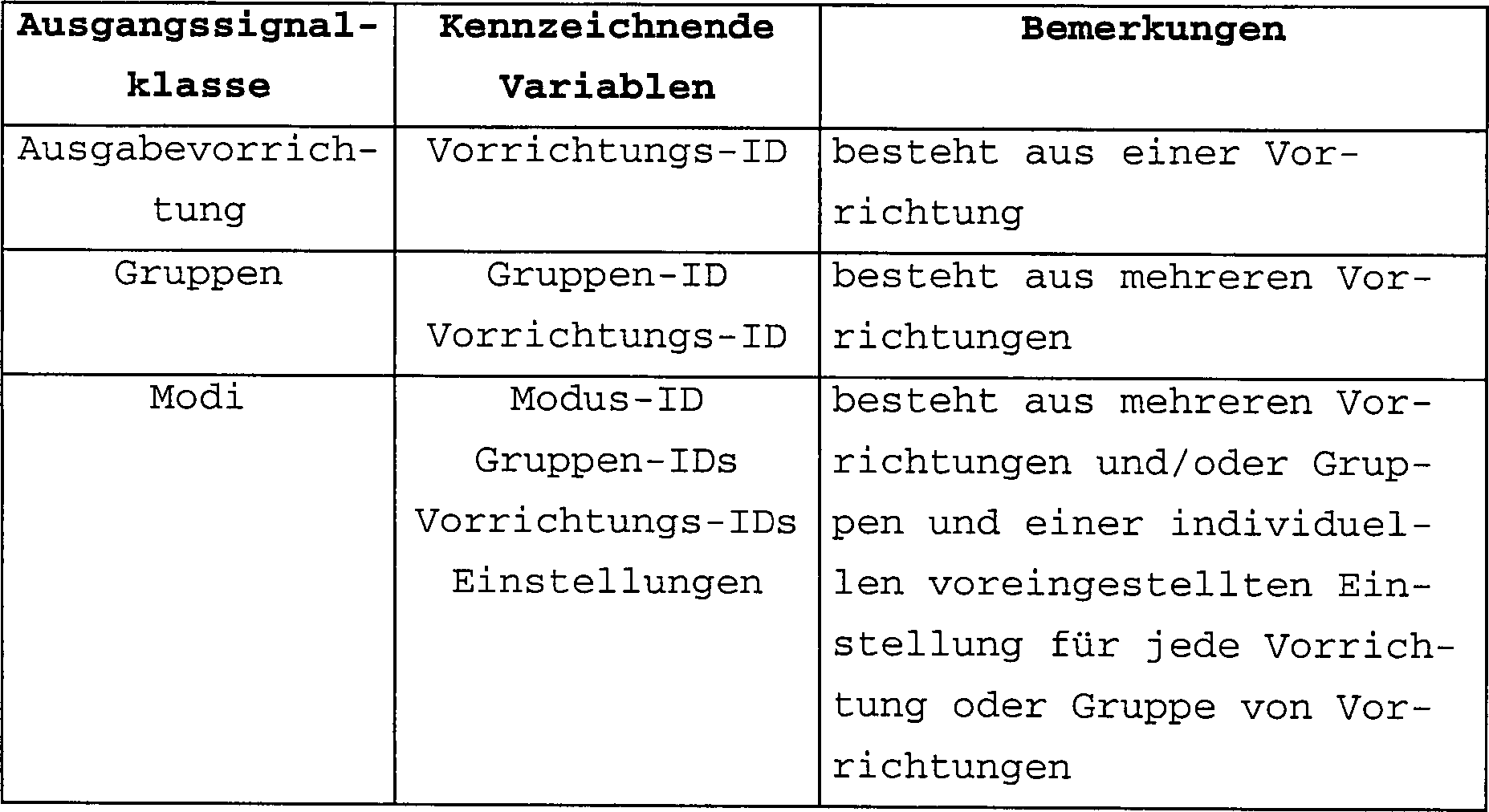
Gruppen sind eine Ausgangssignalklasse, die aus mehreren Vorrichtungen besteht. Diese Ausgangssignalklasse wird zum Steuern mehrerer Ausgabevorrichtungen mit einem einzigen Befehl verwendet. Modi sind im wesentlichen „Gruppen von Gruppen" und/oder „Gruppen von Vorrichtungen", wobei jede Gruppe und/oder Vorrichtung spezifische Einstellungen hat, welche den Betrieb der Vorrichtungen und Gruppen kennzeichnen. Zum Beispiel kann ein Modus aus Vorrichtungen bestehen, die mit Lampen im Wohnzimmer verbunden sind, und die Einstellungen könnten ein Helligkeitsregelungspegel der Leistung sein, die jeder Lampe von jeder Vorrichtung zugeführt wird. Durch Auswählen dieses Modus können alle Lampen im Wohnzimmer auf einen vorbestimmten Helligkeitspegel geregelt werden, wobei der gewünschte Beleuchtungspegel, z. B. zum Fernsehen, erzeugt wird. Die Einstellungen von Vorrichtungen oder Gruppen hängen von der durch jede Vorrichtung ausgeführten Funktion ab und werden für Vorrichtungen und Gruppen einzeln eingestellt. Eine Vorrichtung kann zu einer oder mehreren Gruppen gehören, und jede Gruppe kann zu einer oder mehr Modi gehören.Groups are an output signal class consisting of several devices. This class of output signals is used to control multiple output devices with a single command. Modes are essentially "groups of groups" and / or "groups of devices", each group and / or device has specific settings that characterize the operation of the devices and groups. For example, a mode may consist of devices associated with lamps in the living room, and the settings could be a brightness control level of the power supplied to each lamp by each device. By selecting this mode, all lamps in the living room can be regulated to a predetermined brightness level, the desired level of lighting, e.g. B. for television is generated. The settings of devices or groups depend on the function performed by each device and are set individually for devices and groups. A device can belong to one or more groups and each group can belong to one or more modes.
Rahmenframe
Das Kommunikationsprotokoll der ersten Ausführungsform hat ein allgemeines Format für die Rahmen, welche die Anweisungen und Informationen zwischen den Vorrichtungen des Systems befördern.The communication protocol of the first embodiment has a general format for the framework that the instructions and information between the Transport devices of the system.
Das Rahmenformat gemäß der ersten
Ausführungsform
kann beschrieben werden als: 
- – Die Zahlen
0 bis15 eine Bit-Skala darstellen, welche die Reihenfolge und Größen jedes Teils des Rahmens angibt. Die Reihenfolge, in der die Teile erscheinen, ist nicht einschränkend, und es können andere Reihenfolgen verwendet werden. - – Haus-ID (32-Bit): Die Haus-ID des Systems, in dem dieser Rahmen ausgeführt/empfangen werden sollte.
- – Quellen-ID (8-Bit): Kennung (zweiter Teil der zweiteiligen Kennung) der sendenden Steuerung oder Vorrichtung.
- – Version (3 Bit): Protokoll-/Rahmenformatversion. Dies verleiht die Freiheit, das Rahmenformat gemäß einer Ak tualisierung des Software-Protokolls oder anderen Infrastrukturverbesserungen zu verbessern.
- – R (1 Bit): Richtung des Befehls; 0 wenn ein Befehl ausgegeben wird, 1, wenn ein Befehl bestätigt wird.
- – Typ (4 Bit): Der Rahmentyp entscheidet über die Inhalte des Rests des Rahmens, ob der Rahmen einen Befehl oder z. B. eine Status enthält, und wie die Bezeichnung der Vorrichtungen ausgeführt wird. Die Bezeichnung hängt davon ab, welche und wie viele Geräte adressiert werden sollten. Einige Beispiele für mögliche Rahmentypen sind:
- - The payment
0 to15 represent a bit scale indicating the order and sizes of each part of the frame. The order in which the parts appear is not restrictive, and other orders can be used. - - House ID (32-bit): The house ID of the system in which this frame should be executed / received.
- - Source ID (8-bit): identifier (second part of the two-part identifier) of the sending control or device.
- - Version (3 bit): protocol / frame format version. This gives the freedom to improve the frame format according to an update of the software protocol or other infrastructure improvements.
- - R (1 bit): direction of the command; 0 when a command is issued, 1 when a command is confirmed.
- - Type (4 bit): The frame type decides on the contents of the rest of the frame, whether the frame is a command or e.g. B. contains a status and how the designation of the devices is carried out. The designation depends on which and how many devices should be addressed. Some examples of possible frame types are:


- – Länge (8 Bit): Menge an Bytes in dem Rahmen, beginnend von dem ersten Haus-ID-Wort bis zum letzten Datenbyte ohne Prüfsummenfeld.- Length (8 bits): Amount of bytes in the frame starting from the first house ID word up to the last data byte without checksum field.
- – Befehl (8 Bit): Der Befehl, der ausgeführt werden sollte. Siehe Beispiele für Befehle in Tabelle 3.- Command (8 bits): The command that executed should be. See examples for Commands in Table 3.
- – Befehlswert (8 Bit): Aktueller Wert des ausgegebenen Befehls. Typischerweise ein 8-Bit-Wert, kann aber abhängig von dem Befehl länger sein.- command value (8 bit): Current value of the command issued. typically, an 8-bit value, but can be dependent from the command longer his.
- – Datenbyte (0–n): Die in dem Rahmen enthaltenen Daten.- data byte (0-n): The data contained in the frame.
- – Prüfsumme (8 Bit): Prüfsumme, die zwischen der Haus-ID und dem letzten Byte des Rahmens berechnet wird. Das Prüfsummenfeld selbst wird nicht berechnet.- Checksum (8 bit): Checksum that calculates between the house ID and the last byte of the frame becomes. The checksum field itself is not calculated.
Im folgenden werden einige Beispiele für das allgemeinen Rahmenformat überschreitende Informationen gegeben, die in einem Rahmen enthalten sein können.The following are some examples for the general frame format Given information that can be contained in a frame.
Die folgende Tabelle zeigt einige Beispiele für Befehle und Befehlswerte, die in einem Rahmen ausgegeben werden können:The following table shows some examples for Commands and command values that are output in a frame can:


Mindestens die Befehlswerte der Befehle
Wenn Befehle ausgegeben werden, ist es natürlich wichtig, anzugeben, an welche Vorrichtungen der Befehl adressiert ist. Abhängig von der Anzahl von Vorrichtungen, die in einem Rahmen adressiert werden sollen, können unter Bezug auf Tabelle 2 verschiedene Rahmentypen verwendet werden. Der folgende Rahmentyp weist den Befehl und die einzelnen Adressen, d. h. Vorrichtungs-IDs einer Gruppe von Empfängervorrichtungen, auf.When commands are issued, is it of course important to specify which devices the command addresses is. Dependent on the number of devices addressed in a frame should be able to different frame types can be used with reference to Table 2. The following frame type shows the command and the individual addresses, d. H. Device IDs of a group of receiver devices.

- – Zielvorrichtungs-ID (8 Bit): Feld von 8-Bit-Zielvorrichtungs-IDs, die anzeigen, ob die Empfängervorrichtung auf den Befehl reagieren sollte oder nicht.- Target device ID (8-bit): Field of 8-bit target device IDs that indicate whether the receiver device should respond to the command or not.
Maskierungmasking
Wie aus dem obigen Rahmenformat zu erkennen, macht die Adressierung von Vorrichtungen eine beträchtliche Menge der gesamten zu sendenden Datenbits aus. Es ist ein wichtiges Merkmal des Kommunikationsprotokolls der ersten Ausführungsform der vorliegenden Erfindung, daß es einen Weg zur Verfügung stellt, die Adressierungsdatenbits zu verringern. Durch Verwendung einer Zielvorrichtungs-ID-Maske in dem Rahmenformat können die Adressierungsdaten drastisch verringert werden. Das Maskieren von Vorrichtungs-IDs ist eine Operation, die anzeigt, ob bestimmte der Empfängervorrichtungen auf den Befehl reagieren sollten oder nicht. Ein Register mit Einträgen, von denen jeder Eintrag der Numerierung von Vorrichtungs-Ids entspricht, enthält ein Bitmuster, das als Maske bezeichnet wird, wobei jedes Bit, wenn eine entsprechende Vorrichtungs-ID selektiert werden soll, auf '1' und andernfalls auf '0' gesetzt ist. Durch Senden eines Rahmens, bei dem der Rahmentyp den Maskierungsbereich definiert, vgl. Tabelle 2, zusammen mit der „Zielvorrichtungs-ID-Maske" (wobei jedes Bit anzeigt, ob die Empfängervorrichtung auf den Befehl reagieren sollte oder nicht), nimmt die Adressierung jeder weiteren Vorrichtung nur 1 Bit in Anspruch.As from the frame format above recognize, the addressing of devices makes a considerable one Amount of the total data bits to be sent. It is an important one Feature of the communication protocol of the first embodiment of the present invention that it a way available to reduce the addressing data bits. By using a target device ID mask in the frame format can Addressing data can be drastically reduced. Masking Device IDs is an operation that indicates whether certain of the receiver devices should respond to the command or not. A register with entries from which each entry corresponds to the device ID numbering, contains a bit pattern called a mask, each bit if an appropriate device ID should be selected, set to '1' and otherwise set to '0'. By sending a frame, where the frame type defines the masking area, cf. table 2, together with the "target device ID mask" (each bit indicates whether the receiver device is on the command should react or not) takes the addressing each additional device only 1 bit.
Drei Beispiele für das Maskieren von Vorichtungs-IDs werden im folgenden gegeben. Die Beispiele verwenden Maskengrößen, Typen, Indexierung und Layout gemäß dem Rahmenformat der ersten bevorzugten Ausführungsform der vorliegenden Erfindung. Eine derartige Maskierung kann unter Verwendung anderer Layouts und Formate durchgeführt werden, und die erste Ausführungsform beschränkt nicht die Idee, daß in der Bezeichnung von Vorrichtungen Maskierungen verwendet werden, um Gruppen von Vorrichtungen innerhalb eines beliebigen Kommunikationsnetzwerks zu adressieren.Three examples of masking device IDs are given below. The examples use mask sizes, types, Indexing and layout according to the frame format the first preferred embodiment of the present invention. Such a masking can be done under Use of other layouts and formats can be performed, and the first embodiment limited not the idea that in the Name devices used to mask Groups of devices within any communication network to address.
Zuerst können mit einer 8-Bit-Zielvorrichtungs-ID-Maske bis zu acht Vorrichtungen mit Vorrichtungs-IDs von 1–8 in einem einzigen Byte adressiert werden, was die Datenmenge drastisch verringert. Wenn mit dem unmaskierten Rahmenformat acht Vorrichtungen adressiert werden sollten (Befehl für eine Gruppe von Vorrichtungen), würde die Datenmenge um 8 Byte (8 Vorrichtungs-IDs und das „Anzahl von Vorrichtungen"-Feld statt die „Zielvorrichtungs-ID-Maske") erhöht.First, you can use an 8-bit target ID mask up to eight devices with device IDs from 1-8 in one addressed byte, which drastically reduces the amount of data. When eight devices are addressed with the unmasked frame format should be (command for a group of devices), the amount of data would be 8 bytes (8 device IDs and the “number of devices "field instead of the "target device ID mask").

- – Zielvorrichtungs-ID-Maske (8 Bit): 1-Byte-Zielvorrichtungs-ID-Maske, wobei jedes Bit anzeigt, ob die Empfängervorrichtung auf den Befehl reagieren sollte oder nicht. Das niederwertigste Bit (LSB) stellt die Vorrichtung 1 dar.- Target device ID mask (8 bits): 1 byte target ID mask, each bit indicating whether the receiver device should respond to the command or not. The least significant Bit (LSB) represents device 1.
Wenn wir Vorrichtungen im Bereich von 9–16 adressieren wollten, wäre die einzige Änderung in dem Rahmenformat ein anderer Wert n dem Rahmentypfeld des allgemeinen Rahmenfor mats, nämlich 0100 von Tabelle 2, das LSB in der Maske wäre nun die Vorrichtungs-ID 9.If we have fixtures in the area from 9-16 wanted to address the only change in the frame format another value n the frame type field of the general Framework formats, namely 0100 from Table 2, the LSB in the mask would now be the device ID 9th
Wenn die Vorrichtungen, die adressiert werden sollen, alle Vorrichtungs-IDs im Intervall 1 bis 16 haben, sollte das Rahmenformat vom Rahmentyp „maskierte Vorrichtungs-ID 1–16" sein. Damit können, wie in Tabelle 6 gezeigt, einige oder alle der ersten 16 Vorrichtungs-IDs in zwei Bytes adressiert werden.If the devices that addressed all device IDs in the interval 1 to 16, should the frame format of the frame type "masked device ID 1–16 ". So how shown in Table 6, some or all of the first 16 device IDs can be addressed in two bytes.

- – Zielvorrichtungs-ID-Maske (16 Bit): 2 Byte Zielvorrichtungs-ID-Maske, wobei jedes Bit anzeigt, ob die Empfängervorrichtung auf den Befehl reagieren sollte oder nicht. Das niederwertigste Bit (LSB) stellt die Vorrichtung 1 dar.- Target device ID mask (16 bits): 2 byte target ID mask, each bit indicating whether the receiver device should respond to the command or not. The least significant Bit (LSB) represents device 1.
Viele Systeme in kleinen Haushalten werden das meiste ihrer Kapazität durch die 8- und 16-Bit-Masken, welche 16 Vorrichtungen abdecken, abgedeckt haben. In großen Systemen haben die zu adressierenden Vorrichtungen jedoch Vorrichtungs-IDs über 16, und abhängig von der Anzahl der Vorrichtungen, kann vorteilhaft ein flexibleres Maskierungsverfahren angewendet werden. Während das Rahmentypenfeld typischerweise die der Maske entsprechenden Vorrichtungen definiert, kann der Rahmentyp auch einen Maskenzeigerbereich berücksichtigen, der definiert, welche 8 (oder Anzahl von) Vorrichtungen durch die folgende Zielvorrichtungs-ID-Maske abgedeckt werden.Many systems in small households become most of their capacity through the 8- and 16-bit masks that cover 16 devices, have covered. In large Systems, however, the devices to be addressed have device IDs over 16, and dependent of the number of devices, can advantageously be a more flexible Masking procedures are applied. While the frame type field typically defines the devices corresponding to the mask, the frame type also consider a mask pointer area that defines which 8 (or number of) devices through the following target device ID mask be covered.
Jeder Maskenbereich (mit Ausnahme
des Rahmentyps

- – Maskenzeiger (8 Bit): Der Maskenzeiger zeigt an, auf welche Vorrichtungs-ID-Bereiche sich die Zielvorrichtungs-ID-Maske bezieht.- mask pointer (8 bits): The mask pointer indicates which device ID areas the target device ID mask refers.
- – Zielvorrichtungs-ID-Maske (8 Bit): 1-Byte-Zielvorrichtungs-ID-Maske, wobei jedes Bit anzeigt, ob die Empfängervorrichtung auf den Befehl reagieren sollte oder nicht. Das niederwertigste Bit (LSB) stellt die Vorrichtungs-ID = Maskenzeiger*8 + 1 dar.- Target device ID mask (8 bits): 1 byte target ID mask, each bit indicating whether the receiver device should respond to the command or not. The least significant Bit (LSB) represents the device ID = mask pointer * 8 + 1.
Ein Maskierungsverfahren ähnlich dem weiter oben beschriebenen kann auf die Befehle angewendet werden, die an verschiedene Vorrichtungen ausgegeben werden. Dabei können einige Befehle aus einem Satz vorbestimmter Befehle ausgegeben werden, ohne die Befehle an sich in dem Rahmen zur Verfügung zu stellen.A masking method similar to that described above can be applied to the commands that are output to various devices. Some commands can be issued from a set of predetermined commands, without making the commands themselves available in the frame.
Durch Bereitstellen von Tabellen mit vorbestimmten Befehlen, wie etwa Tabelle 3, in dem Protokoll sowohl auf den Steuerungen als auch auf den Vorrichtungen ist die Maske ein Register aus Einträgen, wobei jeder Eintrag der Numerierung der Befehle entspricht, wobei ein Bitmuster gebildet wird, bei dem jedes Bit, wenn ein entsprechender Befehl ausgewählt werden soll, auf '1' und andernfalls auf '0' gesetzt ist., Die Befehlswerte von Tabelle 3 können einer ähnlichen Maskierung unterzogen werden.By providing tables with predetermined commands, such as Table 3, in the log both on the controls and on the devices Mask a register of entries, where each entry corresponds to the numbering of the commands, where a bit pattern is formed in which each bit, if a corresponding one Command selected should be set to '1' and otherwise is set to '0'. The Command values from Table 3 can a similar one Undergo masking.
Um die Rahmengröße weiter zu verringern, können Daten, wie etwa Felder mit gemessenen Eingabewerten, Bilder oder Textfolgen, wie etwa Programmfolgen, einer Datenkomprimierung unterzogen werden. Das Protokoll kann typische Software-Komprimierungsarchivformate für digitale Daten, wie etwa Zip, gzip, CAB, ARJ, ARC und LZH, anwenden.To further reduce the frame size, data, such as fields with measured input values, images or text sequences, such as program sequences, are subjected to data compression. The protocol can use typical software compression archive formats for digital Apply data such as Zip, gzip, CAB, ARJ, ARC and LZH.
Bestätigungconfirmation
Die Datenübertragung in einer typischen
häuslichen
Umgebung unter Verwendung einer HF-Trägerfrequenz erzeugt die Möglichkeit
des Scheiterns der Übertragung
und des Einbringens von Zufallsfehlern. Die Quellen für das Einführen von
Fehlern umfassen HF-Rauschen von anderen HF-Transceivern und elektrischen Vorrichtungen
im allgemeinen. Das System der vorliegenden Erfindung verwendet
Zwei-Richtungs-HF-Komponenten, was es ermöglicht, von Vorrichtungen Bestätigungen
zurück
zu erhalten, nachdem ein gesendeter Befehl empfangen und ausgeführt wurde.
Dieses Verfahren ist in dem Flußdiagramm
von
Wenn ein Rahmen empfangen wurde, wird der empfangende Teil durch das Kommunikationsprotokoll aufgefordert, den Empfang zu bestätigen. Die Zielvorrichtung, die den Befehl empfangen hat, schickt den Rahmen zurück, wobei das D-Bit und die Vorrichtungs-ID der empfangenden Teile als einzige Vorrichtungs-ID in dem Rahmen gesetzt sind. Das Befehlswertfeld wird verwendet, um den Befehlsrückgabewert (Erfolg, Scheitern, etc.) weiterzugeben. Wenn das D-Bit gesetzt ist, lesen alle Vorrich tungen den Rahmen, so daß die Quellen-ID als Zielvorrichtungs-ID betrachtet wird.If a frame was received, the receiving part is requested by the communication protocol, to acknowledge receipt. The target device that received the command sends the frame back, where the D bit and the device ID of the receiving parts as only device ID are set in the frame. The command value field is used to return the command value (Success, failure, etc.). When the D bit is set all devices read the frame so that the source ID is considered the target device ID.

Die Steuerung sammelt die Bestätigungsantworten und zeigt eine „Befehl erfolgreich ausgeführt"-Meldung an, wenn alle Vorrichtungen den ausgegebenen Befehl empfangen und ausgeführt haben. Wenn die Steuerung nach einer maximalen Anzahl erneuter Versuche von einer oder mehreren Vorrichtungen keine Bestätigungsantworten erhalten hat, oder wenn sie andere Rückgabebefehle als „Erfolg" empfängt, kann sie eine Fehler- oder Warnmeldung anzeigen. Die Einzelheiten einer derartigen Fehlermeldung hängen von der Kapazität des Systems ab.The controller collects the confirmation responses and shows a "command successfully completed "message when all devices have received and executed the issued command. If the control system tries again after a maximum number of has not received confirmation responses from one or more devices, or if they have other return commands as "success" they display an error or warning message. The details of one such an error message of capacity of the system.
Abhängig von der Kapazität der Steuerung kann das System eine Topologiekarte des Systemnetzwerks aufbauen. Diese Topologiekarte weist einen Plan des Gebäudes oder Standorts auf, wo das System installiert ist, wobei die Position der einzelnen Vorrichtungen auf dem Plan markiert ist. Dadurch wird es möglich, einzelne Vorrichtungen betreffende Informationen anzugeben, wie etwa, welche Vorrichtungen einen ausgegebenen Befehl nicht bestätigen, oder welche Eingabevorrichtung was wo festgestellt hat. Wenn die Steuerung keine große Kapazität hat, kann jede Vorrichtung immer noch benannt werden (z. B. „Flurkuppellampe"), damit der Benutzer eine Vorrichtung mit einer Fehlfunktion ausfindig machen kann.Depending on the capacity of the controller, the system can build a topology map of the system network. This topology map has a map of the building or location where the system is installed, with the location of each device marked on the map. This makes it possible to specify information relating to individual devices, such as which devices do not confirm an issued command or which input device has determined what and where. If the controller does not have a large capacity, each device can still be named (e.g. "hall dome lamp"), so that the user can find a malfunctioning device.
WiederholenTo repeat
Aufgrund der begrenzten Reichweite von HF-Signalen werden in dem System Signal-Repeater eingesetzt, um die phy sikalische Abdeckung des Systems zu vergrößern. Repeater sind nach bisherigem Stand der Technik bekannt, aber das System gemäß der vorliegenden Erfindung enthält mehrere neue Merkmale, die im folgenden beschrieben werden.Because of the limited range of RF signals are used in the system signal repeaters, to increase the physical coverage of the system. repeater are known in the prior art, but the system according to the present Invention contains several new features that are described below.
In der ersten Ausführungsform der vorliegenden Erfindung sind alle Vorrichtungen, welche Funktion sie auch immer ausführen, darauf angepaßt, als ein Repeater zu arbeiten, wenn sie von einer Steuerung dazu angewiesen werden.In the first embodiment of the present invention are all devices, what function they do whatever adapted to to work as a repeater when instructed to do so by a controller become.
Wenn Vorrichtungen adressiert werden, ist es wichtig, zu berücksichtigen, daß es sein kann, daß der Rahmen ein oder mehrmals wiederholt werden muß. Der folgende Rahmentyp weist den Befehl, die Zielkennung der adressierten Vorrichtung und die Repeaterkennungen auf, welche die Vorrichtungskennungen der Vorrichtungen sind, die verwendet werden, um das Signal zu wiederholen, damit es die Zielvorrichtung erreicht.When devices are addressed, it is important to take into account that it may be that the frame must be repeated one or more times. The following frame type points the command, the target identifier of the addressed device and the Repeater identifiers, which are the device identifiers of the devices are used to repeat the signal, so it reaches the target device.

- – Anzahl von Repeatern (8 Bit): Die Menge an Repeater-IDs in dem Rahmen.- Number of repeaters (8 bits): The amount of repeater IDs in the frame.
- – Sprünge (8 Bit): 1-Byte-Feld, das anzeigt, wie viele Repeater der Rahmen durchlaufen hat. Dies könnte von den Repeatern als ein Zeiger auf die Repeaterkennung verwendet werden und um zu erkennen, ob sie diesen Rahmen weiterleiten müssen oder nicht.- Jumps (8 bit): 1-byte field that shows how many repeaters the frame traverses Has. This could be from the repeaters can be used as a pointer to the repeater identifier and to see if they need to forward this frame or Not.
- – Repeater-ID (8 Bit): 1-Byte-Repeater-ID, die anzeigt, welchen Weg der Rahmen durchlaufen sollte. Das Sprüngefeld kann als ein Zeiger auf die Repeater-ID-Liste verwendet werden.- Repeater ID (8 bits): 1-byte repeater ID, which shows which way the frame should go through. The jumping field can be used as a pointer to the repeater ID list.
Die Repeater-spezifischen Felder (Anzahl von Repeatern, Sprüngen oder Repeater-IDs) können auf alle weiter oben erwähnten Rahmentypen, die in Tabelle 2 spezifiziert sind, angewendet werden und werden auch in der Bestätigung von empfangenen Rahmen verwendet.The repeater-specific fields (Number of repeaters, jumps or repeater IDs) to all of the above Frame types specified in Table 2 are used and will also be in the confirmation used by received frames.
Das in Bezug auf die Tabellen 5 bis 7 beschriebene Maskierungsverfahren kann auch angewendet werden, wenn in einem Rahmen eine große Anzahl von Repeaterkennungen enthalten ist.That in relation to Tables 5 to 7 masking method described can also be used if in a frame a big one Number of repeater identifiers is included.
Bestimmen von RepeaternDetermine of repeaters
Um in der Lage zu sein, Signale unter Verwendung von Repeatern zu übertragen, wird ein automatisiertes Verfahren durchgeführt, um Vorrichtungen als Repeater zu bestimmen. Es ist wichtig, daß die Menge an Repeatern in einem gegebenen System auf einem Minimum gehalten wird, damit die Antwortzeit so gering wie möglich ist. Es ist wünschenswert, das automatisierte Repeater-Ortungsverfahren nicht zu häufig durchzuführen, da es Zeit benötigt und Energie und dadurch Batterielebensdauer verbraucht.To be able to take signals under To use repeaters to broadcast an automated process is performed to use devices as repeaters to determine. It is important that the amount of repeaters in a given system is kept to a minimum so that the Response time as short as possible is. It is desirable do not perform the automated repeater location procedure too often because it takes time and energy and thereby battery life.
In
Das schließlich mit den notwendigen
Nachdem für die aktuelle Position der
Steuerung Repeater in dem System bestimmt wurden, können alle
Vorrichtungen adressiert werden, wobei das in
Nun weiß die Steuerung, welche Repeater
sie verwenden muß,
um jede Vorrichtung in dem System zu erreichen, und kann einen Rahmen
vom Rahmentyp
Leitwegtabellerouting table
Als eine Alternative zu dem obigen
Ansatz, der verwendet wird, um Vorrichtungen als Repeater zu bestimmen
und zu adressieren, kann das automatisierte Repeater-Erkennungsverfahren,
das in Bezug auf


In diesem alternativen Ansatz wird
das folgende Verfahren verwendet, um zu bestimmen, welche Vorrichtungen
in einem Rahmen des Rahmentyps
- 1. Signal direkt an die Zielvorrichtung senden und auf Bestätigung warten.
- 2. Wenn keine Bestätigung empfangen wird, die erste Vorrichtung mit einer "1" in der Reihe der Zielvorrichtung in der Leitwegtabelle finden, die Kennung dieser Vorrichtung als eine Repeaterkennung in das Signal aufnehmen und Signal wieder senden.
- 3. Wenn keine Bestätigung
empfangen wird, Schritt
2 für die nächsten Vorrichtungen mit einer "1" in der Reihe der Zielvorrichtung in der Leitwegtabelle wiederholen. - 4. Wenn keine Bestätigung
empfangen wird, die erste Vorrichtung mit einer "1" in
der Reihe der Repeatervorrichtung von Schritt
2 in der Leitwegtabelle finden, die Kennung dieser Vorrichtung und der Repeatervorrichtung von Schritt2 als Repeaterkennungen in das Signal aufnehmen und Signal wieder senden. - 5. Wenn keine Bestätigung
empfangen wird, Schritt
5 für die nächsten Vorrichtungen mit einer "1" in der Reihe der Repeatervorrichtung von Schritt2 in der Leitwegtabelle wiederholen. - 6. Wenn keine Bestätigung
empfangen wird, Schritt
5 für die erste Repeatervorrichtung von Schritt3 wiederholen. - 7. etc.
- 1. Send the signal directly to the target device and wait for confirmation.
- 2. If no acknowledgment is received, find the first device with a "1" in the row of the target device in the routing table, include that device's identifier as a repeater identifier in the signal, and send the signal again.
- 3. If no confirmation is received, step
2 repeat for the next devices with a "1" in the row of the target device in the routing table. - 4. If no confirmation is received, the first device with a "1" in the row of the repeater device from step
2 in the routing table, find the identifier of this device and the repeater device from step2 as repeater identifiers in the signal and send the signal again. - 5. If no confirmation is received, step
5 for the next devices with a "1" in the row of the repeater device from step2 Repeat in the route table. - 6. If no confirmation is received, step
5 for the first repeater device from step3 to repeat. - 7. etc.
Die Benutzerschnittstelle verwaltet den Aufbau des Systems durch den Benutzer und ermöglicht es dem Benutzer folglich, Funktionen, wie etwa den Lernvorgang für neue Vorrichtungen, den Aufbau von Gruppen und Modi, das Aktualisieren von zwischen den Steuerungen gemeinsam genutzten Informationen, etc. durchzuführen, wobei davon einige im folgenden beschrieben werden. Diese Funktionen werden durch Programme oder Routinen durchgeführt, die in dem Prozessor der Steuerung gespeichert sind.The user interface manages the structure of the system by the user and allows that User, consequently, functions such as learning for new devices, building groups and modes, updating between perform shared information, etc. with the controls, whereby some of which are described below. These functions are through programs or routines carried out in the processor of the Control are stored.
Steuerungsreplikation/AktualisierungControl replication / update
Da eine Vorrichtung auf alle Steuerungen in einem Haushalt ansprechen sollte, werden alle Steuerungen mit der Haus-ID (d. h. der eindeutigen Kennung der ersten Steuerung, die verwendet wird, um eine Vorrichtung zu programmieren) programmiert. Auch können einige Funktionen, Gruppen, Modi oder andere Tabellen in dem System „universell" in dem Sinn sein, daß bevorzugt wird, die gleichen Tabellen auf allen Steuerungen in dem System zu haben, selbst wenn sie ursprünglich auf einer bestimmten Steuerung erlernt wurden. Dies ist in dem System der vorliegenden Erfindung möglich, da Steuerungen, ob neu oder bereits in Verwendung, voneinander lernen können, um Informationen, etwa durch Kopieren von einer Steuerung auf eine andere oder durch Aktualisieren von Änderungen in den gemeinsam genutzten Informationen einer Steuerung, gemeinsam zu nutzen.As a device on all controls should respond in a household, all controls with the house ID (i.e. the unique identifier of the first controller, used to program a device). Can too some functions, groups, modes or other tables in the system may be "universal" in the sense that preferred the same tables on all controllers in the system to have, even if they were originally were learned on a specific control. This is in the system of the present invention possible because controls, whether new or already in use, learn from each other can, for information, such as copying from one controller to another or by updating changes in the shared information of a controller, collectively to use.
Dies wird bewerkstelligt, indem die erste Steuerung in den „Lehrmodus" und die zweite Steuerung in den „Lernmodus" gebracht wird und die Übertragung von der sendenden ersten Steuerung begonnen wird. Es ist möglich, den Speicher der lernenden Steuerung zu einer vollständigen Kopie/Replikation des entsprechenden Speichers der lehrenden Steuerung zu machen. Auch kann die lernende Steuerung mit Daten von der ersten Steuerung, typischerweise lediglich der Haus-ID, der Vorrichtungstabelle und der Leitwegtabelle, aktualisiert werden, damit die Steuerung die Vorrichtungen lernt, die neu in das System eingeführt wurden.This is accomplished by the first control in the "teaching mode" and the second control is brought into the "learning mode" and the transfer is started by the sending first controller. It is possible that Memory of the learning controller for a complete copy / replication of the appropriate memory of the teaching control. Also can the learning controller with data from the first controller, typically just the house ID, device table and the routing table, so that the controller can control the Learns devices that are new to the system.
Die Übertragung von Daten wird in
einer Folge von Signalen mit dem Rahmentyp

Es ist im Fall der Übertragung größerer Tabellen, wie etwa der Leitwegtabelle, möglich, die Befehlswerte zu maskieren.It is in the case of the transfer larger tables, such as the route table, possible mask the command values.
Lernvorgang für neue VorrichtungenLearning process for new devices
Das System ist sehr flexibel, und zusätzliche Vorrichtungen können mit der Zeit einfach hinzugefügt werden. Wenn dem System eine neue Vorrichtung hinzugefügt wird, muß es wissen, welche Haus-ID und individuelle Vorrichtungs-ID verwendet werden soll. Dieses Verfahren erfordert nur drei Aktionen durch den Benutzer, wobei nur die zu installierende Vorrichtung und eine beliebige Steuerung verwendet werden. Um alles andere kümmert sich das System, und es betrifft oder beeinflußt keine andere Steuerung oder Vorrichtung in dem System. In der ersten bevorzugten Ausführungsform erfährt das System die Anwesenheit der neuen Vorrichtung und weist eine Vorrichtungs-ID in einem automatisierten Verfahren zu, welches den Verfahrenschritten folgt:
- 1. Der Benutzer stellt die Steuerung in einen Lernprogrammierungszustand ein, in dem sie auf alle Signale, nicht nur auf die mit der richtigen Haus-ID, hört.
- 2. Der Benutzer drückt und hält einen Knopf auf der Vorrichtung.
- 3. Die Vorrichtung sendet eine Frage nach der Haus-ID und Vorrichtungs-ID an die, wie in 1 erwähnt, mithörende Steuerung.
- 4. Die Vorrichtung wartet auf einen Rahmen mit der Haus-ID und der Vorrichtungs-ID von der Steuerung.
- 5. Die Steuerung schlägt die nächste verfügbare Vorrichtungs-ID nach und sendet die Haus-ID und die zugewiesene Vorrichtungs-ID an die Vorrichtung.
- 6. Die Vorrichtung speichert die empfangene Haus-ID und Vorrichtungs-ID in einem nichtflüchtigen Speicher.
- 7. Die neue Vorrichtung wird in der Vorrichtungstabelle hinzugefügt und kann der Gruppentabelle hinzugefügt werden und kann benannt werden.
- 1. The user sets the controller in a learning programming state in which it responds to all signals, not just the one with the right house ID.
- 2. The user presses and holds a button on the device.
- 3. The device sends a question about the house ID and device ID to the listening control as mentioned in FIG. 1.
- 4. The device waits for a frame with the house ID and the device ID from the controller.
- 5. The controller looks up the next available device ID and sends the house ID and the assigned device ID to the device.
- 6. The device stores the received house ID and device ID in a non-volatile memory.
- 7. The new device is added to the device table and can be added to the group table and can be named.
Das Signal zum Zuweisen der Vorrichtungs-
(oder Steuerungs-) ID an eine neue Vorrichtung (oder Steuerung)
hat den Rahmentyp

In der Alternative, in der die Vorrichtung ab Fabrik mit einer eindeutigen Vorrichtungs-ID programmiert ist, ist das Verfahren etwas einfacher:
- 1. Der Benutzer stellt die Steuerung in den Vorrichtungsprogrammierungszustand ein und wird aufgefordert, anzugeben, in welcher Gruppe die neue Vorrichtung plaziert werden soll.
- 2. Der Benutzer drückt und hält einen Knopf auf der Vorrichtung, wobei die Vorrichtung ihre Vorrichtungs-ID an die, wie in 1 erwähnt, mithörende Steuerung sendet.
- 3. Die Vorrichtung wartet auf einen Rahmen mit der Haus-ID von der Steuerung.
- 4. Die Steuerung sendet die Haus-ID an die Vorrichtung.
- 5. Die Vorrichtung speichert die empfangene Haus-ID in einem nichtflüchtigen Speicher.
- 6. Die Gruppentabelle in dem nichtflüchtigen Speicher auf der Steuerung wird mit der neuen Vorrichtungs-ID aktualisiert.
- 1. The user sets the controller in the device programming state and is asked to indicate in which group the new device is to be placed.
- 2. The user presses and holds a button on the device, the device sending its device ID to the controller listening in, as mentioned in FIG. 1.
- 3. The device waits for a frame with the house ID from the controller.
- 4. The controller sends the house ID to the device.
- 5. The device stores the received house ID in a non-volatile memory.
- 6. The group table in the non-volatile memory on the controller is updated with the new device ID.
Die Einfachheit dieses Verfahrens liegt an den eindeutigen Adressen aller Vorrichtungen in dem System. Da alle Vorrichtungen einzeln adressiert werden können und aufgrund der Funktionalität des Protokolls kann jede Vorrichtung einzeln aufgebaut und aufgenommen/herausgenommen werden.The simplicity of this procedure is due to the unique addresses of all devices in the system. Since all devices can be addressed individually and because of the functionality of the protocol, each device can be individually set up and added / removed become.
Wenn die Vorrichtung bereits in der Vorrichtungstabelle der Steuerung ist, aber zu einer neuen oder vorhandenen Gruppe hinzugefügt werden soll, weist das Verfahren die folgenden Schritte auf:
- 1. Der Benutzer stellt die Steuerung in den Gruppenprogrammierungszustand ein, und der Benutzer wird aufgefordert, anzugeben, in welcher Gruppe die neue Vorrichtung plaziert werden soll.
- 2. Der Benutzer drückt und hält einen Knopf auf der Vorrichtung.
- 3. Die Vorrichtung sendet ihre Vorrichtungs-ID an die mithörende Steuerung.
- 4. Die Steuerung speichert die empfangene Vorrichtungs-ID in die ausgewählte Gruppentabelle.
- 1. The user places the controller in the group programming state and the user is prompted to indicate in which group the new device is to be placed.
- 2. The user presses and holds a button on the device.
- 3. The device sends its device ID to the listening controller.
- 4. The controller stores the received device ID in the selected group table.
Wenn die Steuerung eine große Kapazität hat und fähig ist, Topologiekarten aufzubauen und zu verwalten, kann das Verfahren anders durchgeführt werden, z. B. indem die Vorrichtung einfach physikalisch installiert wird und danach eine neue Vorrichtung auf der entsprechenden Position in der Topologiekarte auf der Steuerung positioniert wird. Das System kann nun selbst herausfinden, welche (vorhandenen oder neuen) Repeater verwendet werden sollten, um mit der neuen Vorrichtung zu kommunizieren, und kann die Vorrichtung selbst darauf vorbereiten, die Haus- und die Vorrichtungs-ID zu empfangen.If the controller has a large capacity and is able The procedure can be used to build up and manage topology maps performed differently be, e.g. B. by simply physically installing the device and then a new device in the appropriate position is positioned in the topology map on the controller. The system can now find out which (existing or new) repeaters should be used to communicate with the new device and can prepare the device itself, the house and to receive the device ID.
Die weiter oben skizzierten Lernvorgänge können anders organisiert werden, es ist jedoch für die Gesamtfunktionalität des Systems wichtig, daß die Vorrichtung und die Steuerung selbst gegenseitig ihre IDs (zuweisen und) lernen. Vorrichtungen können zu mehreren Gruppen gehören, und eine einzelne Vorrichtung wird in eine Gruppe eingeführt, indem ihre Vorrichtungs-ID in die relevante Gruppentabelle in dem Steuerungsspeicher hinzugefügt wird, und ist folglich zu jeder Zeit ohne Einfluß auf irgendwelche anderen Vorrichtungen.The learning processes outlined above can be different be organized, however, it is for the overall functionality of the system important that the The device and the controller itself assign each other their IDs ( and learning. Devices can belong to several groups, and a single device is inserted into a group by their device ID in the relevant group table in the control memory added and is therefore at all times without influence on any other Devices.
Datenstruktur in der SteuerungData structure in the controller
Um die Signale so kurz und so wenig zu halten, ist das System gemäß der ersten bevorzugten Ausführungsform optimiert, um so einfach wie möglich zu arbeiten, ohne Qualität im Sinne von Zuverlässigkeit, Reichweite/Abdeckung, Vielseitigkeit und Flexibilität einzubüßen. Im folgenden wird die Datenstruktur der Steuerung, welche die gemeinsame Nutzung von Informationen und Ausführung von Funktionen in der geeignetsten Art und Weise ermöglicht, beschrieben.About the signals so short and so little to hold is the system according to the first preferred embodiment optimized to be as simple as possible to work without quality in terms of reliability, range / coverage, Versatility and flexibility losing. in the Following is the data structure of the controller, which is the common Use of information and execution of functions in the most suitable way allows described.
Vorrichtungstabelledevice table
Die Tabelle enthält Informationen über alle Vorrichtungen, die aktuell in dem ganzen System installiert sind. Diese Tabelle wird auch verwendet, um Vorrichtungskennungen an neue Vorrichtungen in dem System zuzuweisen. Diese Tabelle kann auch Informationen über die wesentlichen Eigenschaften oder feste Einstellungen der verschiedenen Vorrichtungen enthalten.The table contains information about all Devices currently installed throughout the system. This table is also used to send device identifiers to new ones Assign devices in the system. This table can too information about the essential characteristics or fixed attitudes of the different Devices included.
Die Tabelle kann auch die Kindersicherheitsfunktion betreffende Informationen, wie etwa den Kode, enthalten.The table can also show the child safety function contain relevant information, such as the code.
Gruppentabellegroup table
Diese Tabelle enthält Informationen darüber, welche Vorrichtungen aus der Vorrichtungstabelle in welcher Gruppe zusammengruppiert sind. Diese Tabelle enthält auch Informationen über die aktuelle Einstellung der bestimmten Gruppe.This table contains information about that, which devices from the device table in which group are grouped together. This table also contains information about the current setting of the specific group.
Modustabellemode table
Diese Tabelle enthält Informationen darüber, welche Gruppen und Vorrichtungen Mitglieder des bestimmten Modus sind, und sie enthält auch die spezifischen Einstellungen jeder Vorrichtung in dem Modus.This table contains information about that, what groups and devices are members of the particular mode and contains them also the specific settings of each device in the mode.
Gruppen- und ModusnamentabelleGroup and mode name table
Diese beiden Tabellen enthalten die benutzerdefinierten alphanumerischen Namen für die verschiedenen Gruppen und Modi.These two tables contain the custom alphanumeric names for the different groups and modes.
Steuerungstabellecontrol table
Diese Tabelle enthält Informationen über alle Steuerungen, die gegenwärtig in dem System sind und wahlweise auch das Datum und die Zeit des letzten Lernvorgangs von einer anderen Steuerung. Diese Tabelle könnte auch Informationen über die wesentlichen Eigenschaften der verschiedenen Steuerungen enthalten.This table contains information about all Controls that are currently are in the system and optionally also the date and time of the last learning process from another controller. This table could as well information about contain the essential properties of the various controls.
Repeatertabellerepeater table
Diese Tabelle enthält Informationen über (die Kennungen aller) alle Vorrichtungen, die als Repeater arbeiten, und Informationen darüber, welche Vorrichtungen von jedem Repeater erreicht werden können.This table contains information about (the Identifications of all) all devices that work as repeaters, and information about which devices can be reached by each repeater.
TopologiekartentabelleTopology map table
Diese Tabelle enthält Informationen über alle bekannten Vorrichtungen in dem System und ihre Position in dem System. Diese Tabelle enthält auch Informationen über die einzelnen Vorrichtungen, wie etwa alphanumerische Namen, wesentliche Eigenschaften und ihre aktuellen Einstellungen.This table contains information about all known devices in the system and their position in the system. This table contains also information about the individual devices, such as alphanumeric names, are essential Properties and their current settings.
In dem früher beschriebenen alternativen Ansatz kann eine Leitwegtabelle, wie etwa Tabelle 10, die Repeatertabelle und die Topologiekarte ersetzten.In the alternative described earlier Approach can be made to a routing table, such as Table 10, the repeater table and replace the topology map.
AuslösemaßnahmentabelleTrigger action table
Diese Tabelle enthält Informationen darüber, welche Maßnahmen zu treffen sind, wenn auf einer oder mehreren der Eingabevorrichtungen ein Auslösepegel erreicht wurde.This table contains information about that, what measures are to be met when on one or more of the input devices a trigger level was achieved.
Ereignistabelleevent table
Diese Tabelle ist ähnlich der Auslösemaßnahmentabelle. Sie enthält bestimmte Ereignisse in der Form von kleinen Programmen, die ausgeführt werden, wenn vorbestimmte Bedingungen erfüllt sind. Beispiele sind das Einschalten der Kaffeemaschine oder der Autoheizung, wenn eine bestimmte Zeit von der Zeitschaltuhr abgelesen wurde.This table is similar to that Trigger actions table. It contains certain events in the form of small programs that run when predetermined conditions are met. These are examples Turn on the coffee machine or car heater if a specific one Time was read from the timer.
Programmtabelleprogram table
Diese Tabelle enthält große Programme, Makros oder Routinen, die auf Befehl ausgeführt werden.This table contains large programs Macros or routines that are executed on command.
Das System gemäß der ersten bevorzugten Ausführungsform kann an einer breiten Vielfalt an Stellen verwendet werden, um eine breite Vielfalt an Funktionen zu steuern. Das System kann in Privathäusern, Hotels, Konferenzzentren, Büros in Betrieben, Lagerhäusern, verschiedenen Institutionen, wie etwa Kindergärten, Schulen, Altenheimen, Behindertenheimen, etc., installiert werden. Im folgenden werden Beispiele für in das System der ersten bevorzugten Ausführungsform eingebaute Funktionen beschrieben.The system according to the first preferred embodiment can be used in a wide variety of places to create a control a wide variety of functions. The system can be used in private homes, hotels, Conference centers, offices in factories, warehouses, various institutions, such as kindergartens, schools, retirement homes, Homes for the disabled, etc. The following will be examples for Functions built into the system of the first preferred embodiment described.
KinderschutzfunktionParental controls
Eine der Funktionen ist die Kinderschutzfunktion. Diese ermöglicht dem Benutzer, die Verwendung einer oder mehrerer Vorrichtungen durch Verwendung eines Kodes oder einer Aktion zu beschränken. Die Beschränkung kann mehrere Auswirkungen haben, d. h.:
- – Die Vorrichtung oder das damit verbundene Gerät sind ausgeschaltet und können nicht eingeschaltet werden, bis ein gültiger Kode eingegeben wurde oder eine vorbestimmte Aktion durchgeführt wurde. In der ersten bevorzugten Ausführungsform hebt das dreimalige Drücken eines Bedienelements auf der jeweiligen Vorrichtung den Schutz auf. Wird z. B. verwendet, um Kinder vor Haushaltsgeräten, wie etwa Öfen, Toastern oder Kochplatten, zu schützen.
- – Die Vorrichtung oder das damit verbundene Gerät können nur auf einem bestimmten Pegel, für eine spezifizierte Zeitdauer oder innerhalb einer bestimmten Zeitdauer arbeiten, es sei denn, ein gültiger Kode wurde angegeben. Wird z. B. verwendet, um den Ausgangssignalpegel einer Audioanlage zu beschränken, die Menge des Fernsehschauens der Kinder zu beschränken, wenn die Eltern nicht da sind, oder die Betriebsdauern des Solariums auf die zu beschränken, die vom Kunden tatsächlich bezahlt wurden.
- – Der Zustand oder Betriebspegel der Vorrichtung oder des damit verbundenen Geräts können nicht verändert werden, bis ein gültiger Kode angegeben wurde. Wird z. B. verwendet, um die Heißwassertemperatur auf einer konstanten Temperatur fest einzustellen, oder den Thermostat für die Klimaanlage fest einzustellen.
- - The device or the device connected to it are switched off and cannot be switched on until a valid code has been entered or a predetermined action has been carried out. In the first preferred embodiment, pressing an operating element three times on the respective device removes the protection. Is z. B. used to protect children from household appliances such as ovens, toasters or hot plates.
- - The device or the device connected to it can only operate at a certain level, for a specified period of time or within a certain period of time, unless a valid code has been specified. Is z. B. used to limit the output signal level of an audio system, limit the amount of television viewing of the children when the parents are not there, or limit the operating time of the solarium to those that were actually paid for by the customer.
- - The state or operating level of the device or the device connected to it cannot be changed until a valid code has been entered. Is z. B. used to fix the hot water temperature to a constant temperature, or to fix the thermostat for the air conditioning.
Zeitschaltungtiming
Jede Steuerung kann eine Uhr aufweisen, die das Datum und die Zeit angibt. Diese Uhr wird für Zeitschaltungsfunktionen, wie etwa zur Ausführung vorprogrammierter Ereignisse, verwendet und kann von verschiedenen Teilen von in der Steuerung enthaltenen Programmen gelesen werden.Each controller can have a clock which gives the date and time. This watch is used for timing functions, how about execution pre-programmed events, used and can be of different Parts of programs contained in the controller can be read.
Leistung und BeleuchtungPerformance and lighting
In einer zweiten bevorzugten Ausführungsform, auch Leistung- & Beleuchtungssteuerung genannt, weist das System eine Reihe von Produkten zur Steuerung des Leistungspegels von mit den Vorrichtungen verbundenen elektrischen Geräten, wie etwa Lampen, Klimaanlage und Küchengeräten, auf.In a second preferred embodiment, also power & lighting control called, the system has a number of products for control the power level of electrical associated with the devices Devices, such as lamps, air conditioning and kitchen appliances.
Abgesehen davon, daß es ein dem Leistungs- & Beleuchtungssteuerungssystem ist, dient das System der zweiten bevorzugten Ausführungsform dazu, eine Grundlage für ein komplettes Haussteuerungssystem einschließlich anderer Teilsystemen, wie etwa Hochspannungswechselstromsteuerung, Alarmsystemsteuerung, Zugangssteuerung, etc., zu bilden.Aside from being a the power & lighting control system the system serves the second preferred embodiment to provide a basis for a complete home control system including other subsystems, such as high voltage AC control, alarm system control, Access control, etc.
Das Automatisierungssystem der zweiten bevorzugten Ausführungsform ist auf der gleichen Plattform aufgebaut wie das Automatisierungssystem der ersten bevorzugten Ausführungsform. Folglich ist die Beschreibung der zweiten bevorzugten Ausführungsform eine detailliertere Beschreibung einiger der Funktionen, die in Bezug auf die erste bevorzugte Ausführungsform beschrieben wurden, und es wird vorausgesetzt, daß die in Bezug auf die erste bevorzugte Ausführungsform beschriebenen Merkmale auch in der zweiten Ausführungsform gültig sind.The automation system of the second preferred embodiment is built on the same platform as the automation system of the first preferred embodiment. Thus, the description of the second preferred embodiment is a more detailed description of some of the functions described with respect to the first preferred embodiment, and is assumed to be the features described in relation to the first preferred embodiment are also valid in the second embodiment.
Die Vorrichtungen
In der in Bezug auf
Die folgende Beschreibung des Leistungs- & Beleuchtungssteuerungssystems beschäftigt sich hauptsächlich mit den Aspekten, die in der Beschreibung von allgemeinen Teilen des begrifflichen skalierbaren Systems, die in der Beschreibung der ersten bevorzugten Ausführungsform des Automatisierungssystems auf hoher Ebene gegeben wurde, nicht enthalten sind. Jedoch sind Details und Merkmale, die nur in Bezug auf die zweite Ausführungsform beschrieben werden, auch in Bezug auf die erste bevorzugte Ausführungsform gültig.The following description of the power & lighting control system employed mainly with the aspects described in the description of general parts of the conceptual scalable system described in the description the first preferred embodiment automation system was given at a high level, not are included. However, details and features are only related to the second embodiment be described, also with respect to the first preferred embodiment valid.
Das Leistungs- & Beleuchtungssteuerungssystem besteht aus den folgenden Elementen.The power & lighting control system is in place from the following elements.
Steuerungencontrols
In der Leistungs- & Beleuchtungsausführungsform ist die Steuerung ein mobiles Steuerpult, wie etwa eine Fernsteuerung, so daß die Verwendung oder Programmierung des Systems nicht auf bestimmte Orte beschränkt ist. Steuerungen haben eine Anzeige, wie etwa eine LCD-Anzeige (Flüssigkristallanzeige). Die Steue rungen können wahlweise an einen Computer anschließen; überdies kann ein Computer auch als eine Steuerung in dem System arbeiten. Die erste Implementierung und häufig auch die spätere Einstellung einer Vorrichtung werden in der Nähe der Vorrichtung durchgeführt. Obwohl die Datenprotokolle die Adressierung von Vorrichtungen unter Verwendung der Vorrichtungskennungen nutzen, kann sich die Person, die die Programmierung durchführt, auf ihre visuelle Bestätigung der Verbindung eines Geräts mit einer gegebenen Vorrichtung verlassen. Folglich ist die Programmierschnittstelle nicht auf die Fähigkeit des Benutzers angewiesen, sich Vorrichtungskennungen, zugewiesene Nummern oder ähnliches zu merken.In the power & lighting embodiment the control is a mobile control panel, such as a remote control, So that the Do not use or program the system to specific locations limited is. Controls have a display, such as an LCD (liquid crystal display). The controls can optionally connect to a computer; a computer can also work as a controller in the system. The first implementation and often also the later one Adjustment of a device is carried out in the vicinity of the device. Even though the data protocols using the addressing of devices of the device identifiers, the person who is the Programming, for their visual confirmation connecting a device leave with a given device. Hence the programming interface not on ability instructed the user to assign device identifiers Numbers or the like to notice.
- – Den Ein-/Aus-Knopf für alles, der entweder alle Ausgabevorrichtungen, abgesehen von den Vorrichtungen, die als nicht eingeschlossen konfiguriert wurden, ein- oder ausschaltet. Die Einrichtung dieser Funktion wird später spezifiziert.
- – Die acht Geschwindigkeitsknöpfe für den schnellen Zugang zu den am häufigsten verwendeten Gruppen oder Modi.
- – Den Gruppenknopf, der den Status der Geschwindigkeitsknöpfe als Gruppen einstellt.
- – Den Modenknopf, der den Status der Geschwindigkeitsknöpfe als Modi einstellt.
- – Den OK-Knopf, der hauptsächlich in dem Menüsystem verwendet wird.
- – Die Links- und 0Rechtsknöpfe, die unter anderem verwendet werden, um in dem Menüsystem zu manövrieren.
- – Unter anderem können mit der Steuerung die folgenden Aktionen durchgeführt werden:
- – Vorrichtungen so programmieren, daß sie zu dem System gehören (d. h. sie mit der eindeutigen Haus-ID-Nummer zu programmieren)
- – Kennungen an neue Vorrichtungen zuweisen
- – Vorrichtungen so programmieren, daß sie zu einer oder mehreren Gruppen gehören
- – Ein-/Ausfunktion für eine gegebene Gruppe ausführen
- – Intensitätsregelungsfunktion für eine gegebene Gruppe ausführen
- – Vorrichtungen so programmieren, daß sie zu einer oder mehreren Modi gehören
- – Einen gegebenen Modus ausführen
- – Benennen einer gegebenen Gruppe mit alphanumerischen Zeichen
- – Benennen eines gegebenen Modus mit alphanumerischen Zeichen
- – Einstellen eines Kinderschutzes auf einer Vorrichtung
- – Programmieren der Zeitschaltung
- – Auslösen und Unterbrechen der Tastensperrfunktion
- – Etc.
- The on / off button for anything that either turns on or off all of the output devices, except for the devices that have been configured as not included. The setup of this function will be specified later.
- - The eight speed buttons for quick access to the most commonly used groups or modes.
- - The group button that sets the status of the speed buttons as groups.
- - The mode button that sets the status of the speed buttons as modes.
- - The OK button, which is mainly used in the menu system.
- - The left and right buttons, which are used, among other things, to maneuver in the menu system.
- - Among other things, the following actions can be carried out with the control:
- - Program devices so that they belong to the system (ie to program them with the unique house ID number)
- - Assign identifiers to new devices
- - Program devices so that they belong to one or more groups
- - Execute on / off function for a given group
- - Execute intensity control function for a given group
- - Program devices to belong to one or more modes
- - Execute a given mode
- - Name a given group with alphanumeric characters
- - Name a given mode with alphanumeric characters
- - Setting child protection on a device
- - Programming the timer
- - Triggering and interrupting the key lock function
- - Etc.
Innerhalb eines Systems können mehrere Steuerungen verwendet werden, und Signale von einer ersten zu einer zweiten Steuerung können betreffen:
- – das Lernen der Haus-ID und das Zuweisen der Steuerungs-ID
- – die Replikation oder Aktualisierung verschiedener Daten auf Steuerungen.
- - learning the house ID and assigning the control ID
- - The replication or update of various data on controllers.
Ausgabevorrichtungenoutput devices
Die Ausgabevorrichtungen sind betriebsbereit zwischen eine Stromquelle und ein elektrisches Gerät, typischerweise in der Form einer mit einer Stromversorgungssteckdose verbundenen Anschlußdose, geschaltet. Die Ausgabevorrichtungen können das Umschalten, die Intensitätsregelung und wahlweise das Messen der an das elektrische Gerät zugeführten Leistung oder des Stroms durchführen. Auch sind die Ausgabevorrichtungen fähig, in dem System als Repeater zu arbeiten.The dispensers are ready for use between a power source and an electrical device, typically in the form of a plug connected to a power outlet Junction box, connected. The output devices can switch, the intensity control and optionally measuring the power supplied to the electrical device or the current. The output devices are also capable of acting as repeaters in the system to work.
Es ist eine Anzahl verschiedener Arten von Ausgabevorrichtungen machbar, die von Niederspannungsschaltern bis zu Hochspannungswechselstrom-Ausgabevorrichtungen, etc. reicht. Jede Ausgabevorrichtung hat nur einen Bedienknopf. Dieser Knopf wird jedes Mal verwendet, wenn die Vorrichtung während Programmierungsprozeduren einer Steuerung ihre Vorrichtungs-ID mitteilen sollte. Der Knopf kann auch verwendet werden, um die von der Vorrichtung gelieferte Leistung ein-/auszuschalten und die Intensität zu regeln, ohne daß eine Steuerung verwendet wird. Diese Funktion kann jedoch durch die Kinderschutzfunktion außer Kraft gesetzt werden, indem der Knopf für Leistungseinstellungszwecke inaktiv gemacht wird. Die verschiedenen Funktionen des Knopfes werden genutzt, indem der Knopf für verschiedene Zeitdauern gedrückt wird, z. B. eine kurze Dauer zum Ein- /Ausschalten und zum Hoch- und Runterregeln der Intensität, wenn der Knopf fortlaufend gedrückt wird.It is a number of different ones Types of output devices feasible from low voltage switches up to high voltage AC output devices, etc. Each dispenser has only one control button. This button will used every time the device during programming procedures a controller should communicate its device ID. The button can also be used to match the one supplied by the device Power on / off and regulate the intensity without any control is used. However, this function can be done through the child protection function inoperative be set by the button for power setting purposes is made inactive. The different functions of the button are used by the button for different durations pressed will, e.g. B. a short duration for switching on / off and for up and down regulation the intensity, if the button is pressed continuously becomes.
Unter anderem können die Ausgabevorrichtungen die folgenden Tätigkeiten durchführen:
- – Eine Steuerung über ihr Vorhandensein informieren und sich darauf einstellen, die Haus-ID und die Vorrichtungs-ID zu empfangen
- – Durch Verwendung eines Knopfes auf der Vorrichtung zwischen Ein und Aus hin- und herschalten
- – Die Stromintensität durch Verwendung eines Knopfes auf der Vorrichtung regeln
- – Von einer Steuerung empfangene Befehle ausführen
- – Stromintensität regeln
- – Den empfangenen Befehl für andere Ausgabevorrichtungen wiederholen
- – Den Strom ein-/ausschalten
- – Empfangene und ausgeführte Befehle bestätigen
- – Mit dem Vorrichtungsstatus antworten
- – Messen der an das elektrische Gerät, das mit der Vorrichtung verbunden ist, zugeführten Leistung oder des Stroms und Speichern, Verarbeiten und Senden der gemessenen Informationen.
- - Inform a controller of its existence and prepare to receive the house ID and the device ID
- - Toggle between on and off using a button on the device
- - Adjust the current intensity by using a button on the device
- - Execute commands received from a controller
- - Regulate current intensity
- - Repeat the received command for other output devices
- - Turn the power on / off
- - Confirm received and executed commands
- - Reply with the device status
- Measuring the power or current supplied to the electrical device connected to the device and storing, processing and sending the measured information.
Die folgenden Abschnitte beschreiben einige der in dem Beleuchtungssystem enthaltenen Funktionalitäten.The following sections describe some of the functionalities contained in the lighting system.
Umschalten von Gruppen oder ModiSwitch groups or modes
Durch Drücken des „Gruppenknopfes" gibt der Benutzer Funktionen ein, die mit einem einzelnen oder einer Gruppe von Geräten, wie etwa Lampen, zu tun haben. Durch Drücken des „Modusknopfes" gibt der Benutzer Funktionen ein, die mit Modi (z. B. Einstellen einer vorbestimmten Beleuchtung für den Raum) zu tun haben.By pressing the "group button" the user gives Features that work with a single or group of devices, such as such as lamps. By pressing the "mode button" the user gives Functions associated with modes (e.g. setting a predetermined Lighting for the space) have to do.
Ein-/Ausschalten von GruppenSwitch groups on / off
Ein Benutzer kann ein einzelnes Gerät oder eine Gruppe davon ein- oder ausschalten, indem er entweder die Geschwindigkeitsknöpfe 1–8 verwendet oder indem er den Verschiebungsknopf verwendet. Wenn der Benutzer den Knopf 1–8 benutzt, ist nur eine kurzes Drücken erforderlich. Der Knopf wirkt als ein Umschalter. Wenn der Verschiebungsknopf benutzt wird, muß der Benutzer bis zur gewünschten Gruppe schieben und einen OK-Knopf drücken.A user can use a single device or a device Turn group of them on or off using either speed buttons 1-8 or by using the move button. If the user button 1-8 used is just a short press required. The button acts as a toggle. If the shift button is used, the User up to the one you want Slide the group and press an OK button.
Intensitätseinstellung für Gruppenintensity adjustment for groups
Ein Benutzer kann die Intensität des Stroms für ein einzelnes Gerät oder eine Gruppe davon, wie etwa Lampen (gleiche Gruppe wie die Ein-/Ausfunktion) regeln, indem er entweder die Geschwindigkeitsknöpfe 1–8 verwendet oder indem er den Verschiebungsknopf verwendet. Wenn die Knöpfe 1–8 verwendet werden, wird die Intensitätsregelung ausgelöst, wenn der Knopf fortlaufend gedrückt wird. Wenn der richtige Intensitätspegel erreicht ist, wird der Knopf losgelassen. Wenn der Verschiebungsknopf benutzt wird, muß der Benutzer bis zur gewünschten Gruppe schieben und zusätzliche Knöpfe drücken, um die Intensität herauf-/herunter zu regeln.A user can control the intensity of the current for a single device or a group of them, such as lamps (same group as that On / off function) using either speed buttons 1-8 or by using the move button. When buttons 1-8 are used will be the intensity control fires if the button is pressed continuously becomes. If the right intensity level the button is released. If the shift button is used, the User up to the one you want Group push and additional Buttons to press, about the intensity to regulate up / down.
Befehlsbestätigung auf einer AnzeigeCommand confirmation on an ad
Jeder von einem Benutzer ausgelöste Befehl wird über die Anzeige bestätigt. Eine typische Bestätigung könnte zum Beispiel „Alle Lichter sind jetzt aus." sein. Nach dem Betätigen einer Vorrichtung erwartet das Steuerpult den Empfang ei ner Bestätigung von der Vorrichtung, die den Befehl ausgeführt hat. Zwei Ereignisse können auftreten:
- – Die Vorrichtung antwortet nicht mit einer Bestätigung: Die Steuerung zeigt z. B. an: „außer Reichweite oder Vorrichtung defekt".
- – Die Vorrichtung antwortet mit einer Fehlermeldung, wie etwa daß im Stromnetz kein Strom festgestellt wurde: Die Steuerung zeigt z. B. an: „Birne oder Lampe defekt".
- – Die Vorrichtung antwortet, daß der Befehl ausgeführt wurde: Die Steuerung zeigt z. B. an: „Alles OK".
- - The device does not respond with an acknowledgment: The control shows e.g. B. on: "Out of range or device defective".
- - The device replies with an error message, such as that no current was found in the power grid. B. on: "Bulb or lamp defective".
- - The device replies that the command has been carried out. B. to: "Everything OK".
Modus-ProgrammierfunktionMode programming function
Modi können in dem Steuerpult programmiert werden, indem die verschiedenen Vorrichtungen auf den gewünschten Strompegel voreingestellt werden und dieser Pegel danach in dem Steuerpult gespeichert wird. Modi können unter Verwendung der Knöpfe 1–8 oder unter Verwendung des Verschiebungsknopfes für eine zusätzliche Speicherung gespeichert werden.Modes can be programmed in the control panel by placing the various devices on the desired one Current levels are preset and this level afterwards in the Control panel is saved. Modes can be set using buttons 1-8 or saved using the shift button for additional storage become.
Modus-EinstellfunktionMode setting function
Ein Benutzer kann unter Verwendung der 1–8 Knöpfe des Steuerpults voreingestellte Modi (z. B. Fernsehmodus oder Arbeitsmodus) aktivieren. Wenn der Verschiebungsknopf verwendet wird, muß der Benutzer bis zur gewünschten Gruppe schieben und einen OK-Knopf drücken.A user can use the 1-8 Buttons Control panel preset modes (e.g. TV mode or work mode) activate. If the move button is used, the user must go to to the desired one Slide the group and press an OK button.
Alles Ein-/AusschaltenTurn everything on / off
Ein Benutzer kann alle Schalter ein- oder ausschalten, indem er den „Alles Ein/Aus"-Knopf drückt. Eine Vorrichtung wird als Voreinstellung so programmiert, daß sie auf den „Alles Ein/Aus"-Knopf anspricht, aber sie kann auch programmiert werden, es nicht zu tun.One user can turn on all switches or turn it off by pressing the "all on / off" button. One device is programmed as a default so that it is based on the "Everything On / off button but it can also be programmed not to do it.
Alles Ein-/Aus-ProgrammierenAll programming on / off
Sollte es für einen Benutzer erforderlich sein, daß ein bestimmtes Gerät nicht auf „Alles Ein/Aus" anspricht, kann dies erledigt werden, indem dies auf dem Steuerpult eingestellt wird. Dies könnte z. B. vorteilhaft für das Aquarium oder die Außenlichter sein.Should it be necessary for a user be that a specific device not on "Everything On / off " this can be done by setting this on the control panel. this could z. B. advantageous for the aquarium or the outside lights his.
Zufällige Ein-/Aus-EinstellungenRandom on / off settings
Der Benutzer kann das Steuerpult verwenden, um einzustellen, daß eine Vorrichtung sich zufällig ein- und ausschaltet (wird z. B. verwendet, um Einbrecher fernzuhalten). Die Vorrichtung wird sich z. B. mit einem 3-Stunden-Intervall weiter ein- und ausschalten und diese Aktion abbrechen, wenn sie das nächste Mal eine Instruktion von dem Steuerpult empfängt. Das Zeitintervall, in dem das Steuerpult zufällig ein- und ausschalten sollte, kann auch eingestellt werden (z. B. von 18:00 bis 23:00).The user can use the control panel to set a device to turn on and off accidentally (used, for example, to keep intruders away). The device will z. B. on and off with a 3 hour interval and cancel this action the next time you do one Instruction received from the control panel. The time interval in which the control panel should switch on and off accidentally can also be set (e.g. from 18:00 to 23:00).
Zufälliges Ein-/Aus-ProgrammierenRandom on / off programming
Sollte es für einen Benutzer erforderlich sein, daß ein bestimmtes Gerät nicht auf „Zufälliges Ein/Aus" anspricht, kann dies erledigt werden, indem dies auf dem Steuerpult eingestellt wird. Dies könnte z. B. vorteilhaft für das Aquarium oder die Außenlichter sein.Should it be necessary for a user be that a specific device cannot respond to "random on / off" this can be done by setting this on the control panel becomes. this could z. B. advantageous for the aquarium or the outside lights his.
Zurücksetzen von VorrichtungenDevice reset
Alle Vorrichtungen können zurückgesetzt werden, wobei die Haus-ID und die Vorrichtungs-ID, die in der Vorrichtung enthalten sind, gelöscht werden und alle Bezüge auf die Vorrichtungs-ID in der Steuerung gelöscht werden. In der Leistung- & Beleuchtungsausführungsform wird das Zurücksetzen durchgeführt, indem die Steuerung in den „Vorrichtungsrücksetzungs"Modus eingestellt wird und der Bedienknopf auf der Vorrichtung gedrückt wird. Dies veranlaßt die Vorrichtung dazu, Informationen an die Steuerung zu senden, welche dann das Zurücksetzen durchführt.All devices can be reset with the house ID and device ID used in the device are included, deleted and all references on the device ID in the controller. In the power & lighting embodiment, the reset carried out, by setting the controller in the "device reset" mode and the control button on the device is pressed. This causes the device to send information to the controller, which then resetting performs.
Programmieren und LernenProgramming and learning
Im folgenden werden die Verfahren
zum Durchführen
einiger der Programmierungs- und Lernfunktionen in den Systemen
unter Bezug auf
Gruppenmenügroup menu
Wenn im Hauptmenü das Gruppenmenü selektiert wird, können die folgenden drei Dinge für die Gruppen erledigt werden, nachdem diese an sich während des Hinzufügens neuer Vorrichtungen erzeugt wurden:
- – Die Gruppe benennen: Jede Gruppe kann mit alphanumerischen Zeichen benannt werden, um die Benutzerfreundlichkeit zu verbessern.
- – Einen
Schalter von einer Gruppe entfernen: Wenn die verschiedenen Vorrichtungen
zu einer bestimmten Gruppe hinzugefügt wurden, dann ermöglicht es
diese Menüfunktionalität dem Benutzer,
einzelne Schalter von einer bestimmten Gruppe zu entfernen. Das
Verfahren, wie dies gemacht wird, ist in
20 gezeigt. Zuerst selektiert der Benutzer die Menüoption „Schalter von Gruppe entfernen" und wird nach der Gruppennummer gefragt, in der die Vorrichtung entfernt werden soll. Dann muß der Benutzer einen Knopf auf der Ausgabevorrichtung drücken, damit die Steuerung die zu entfernende Vorrichtungs-ID erhält. Wenn der Knopf auf der Ausgabevorrichtung gedrückt wurde, wird die bestimmte Vorrichtung aus der Gruppentabelle entfernt, und das Menüsystem kehrt ins Hauptmenü zurück. - – Eine Gruppe löschen: Dieser Menüpunkt ermöglicht es dem Benutzer, eine Gruppe vollständig zu löschen.
- - Name the group: Each group can be named with alphanumeric characters to improve usability.
- Remove a switch from a group: When the various devices have been added to a particular group, this menu functionality enables the user to remove individual switches from a particular group. The procedure for how this is done is in
20 shown. First the user selects the menu item "Remove switch from group" and is asked for the group number in which the device is to be removed. Then the user has to press a button on the output device in order for the controller to receive the device ID to be removed. If the button on the output device has been pressed, the particular device is removed from the group table and the menu system returns to the main menu. - - Delete a group: This menu item enables the user to delete a group completely.
Modusmenümode menu
Modi sind Gruppen von Vorrichtungen, bei denen die Einstellung jeder Vorrichtung auf einen gewünschten Intensitätspegel oder Strom eingestellt ist. Wenn in dem Hauptmenü das Modusmenü selektiert wird, sind in dem Modusmenüabschnitt die folgenden Optionen verfügbar:
- – Einen
Modus erzeugen: Dieser Menüpunkt
ermöglicht
es dem Benutzer, Vorrichtungen zu einem Modus zusammenzufügen. Das
Verfahren ist in
21 skizziert. Der Benutzer selektiert zuerst die Menüoption „Modus erzeugen" und wird aufgefordert, Vorrichtungen zu selektieren, die in dem Modus enthalten sein sollen. Der Benutzer drückt dann einen Knopf auf allen Ausgabevorrichtungen, die in den Modus aufgenommen werden sollen, und drückt OK, wenn er fertig ist. Die Ausgabevorrichtungen senden dann ihren aktuellen Intensitätsregelungspegel an die Steuerung. Dann wird der Benutzer nach einer Modusnummer gefragt, um die bereits selektierten Vorrichtungen hinzuzufügen. Wenn der Modus bereits verwendet wird, muß der Benutzer bestimmen, ob der Modus durch die ausgewählten Vorrichtungen ersetzt werden soll oder eine andere Modusnummer gewählt wird. Der Benutzer hat dann die Möglichkeit, den Modus zu benennen. Der Benutzer kann nun in einem Umschaltmenü unter Verwendung der Links- /Rechts- und OK-Knöpfe alphanumerische Zeichen selektieren. Wenn der Name eingetippt ist, drückt der Benutzer den OK-Knopf für mehr als 2 Sekunden, wodurch die Steuerung den Modusname speichert und zum Hauptmenü zurückkehrt. - – Einen Modus benennen: Jeder Modus kann mit alphanumerischen Zeichen benannt werden, um die Benutzerfreundlichkeit zu verbessern.
- – Schalter von Modus entfernen: Wenn die verschiedenen Vorrichtungen zu einem bestimmten Modus zusammengefügt wurden, dann ermöglicht es diese Menüfunktionalität dem Benutzer, einzelne Schalter wieder von einem bestimmten Modus zu entfernen. Dieses Verfahren ist äquivalent zu dem Verfahren, das beim Entfernen von Schaltern von Gruppen verwendet wird.
- – Einen Modus löschen: Dieser Menüpunkt ermöglicht es dem Benutzer, einen Modus vollständig zu löschen.
- - Create a mode: This menu item enables the user to combine devices into one mode. The procedure is in
21 outlined. The user first selects the "Create Mode" menu option and is prompted to select devices to be included in the mode. The user then presses a button on all of the output devices to be included in the mode and presses OK when he is done The output devices then send their current intensity control level to the controller, then the user is asked for a mode number to add the devices already selected, and if the mode is already in use, the user must determine whether the mode is replaced by the selected devices or another mode number is selected. The user then has the option of naming the mode. The user can now select alphanumeric characters in a toggle menu using the left / right and OK buttons. When the name is typed in, the user presses the OK button for more than 2 seconds, causing the The controller saves the mode name and returns to the main menu. - - Name a mode: Each mode can be named with alphanumeric characters to improve usability.
- - Remove switches from mode: When the various devices have been merged into a specific mode, this menu functionality enables the user to remove individual switches from a specific mode. This procedure is equivalent to the procedure used when removing switches from groups.
- - Delete a mode: This menu item enables the user to delete a mode completely.
Die „Alles Ein/Aus-" Funktionalität wird voreingestellt für alle Vorrichtungen, welche die Steuerung kennt. Einzelne Schalter können wiederholbar von dieser Funktion entfernt oder hinzugefügt werden. Es besteht auch eine Möglichkeit, kundenspezifisch anzupassen, ob der Knopf ein Ein-/Aus-Wechselschalter ist oder ob dieser Knopf nur als Ausschalter zu verwenden ist.The "All on / off" functionality is preset for all Devices that the controller knows. Individual switches can be repeated removed or added by this function. It also exists a possibility, Customize whether the button is an on / off switch or whether this button should only be used as a switch.
SteuerunasreplikationSteuerunasreplikation
Um die Verwendung mehrerer Steuerungen,
die innerhalb der gleichen Haus-ID arbeiten, zu erleichtern, hat
das Produkt das Merkmal, daß sie
sich gegenseitig mit den verschiedenen Tabellen und Einstellungen aktualisieren.
Das Aktualisierungsverfahren ist in
Hardwarehardware
Leistungsmesserpower meter
Einige oder alle Ausgabevorrichtungen
können
Einrichtungen umfassen, um die an das eine oder die mehreren Geräte, die
mit jeder Vorrichtung verbunden sind, zugeführte Leistung zu messen. Die
Leistungsmessungseinrichtungen sind Einrichtungen zum Messen des
bei konstanter Spannung an das Gerät zugeführten Stroms, um die Bestimmung
der Leistung, z. B. in kW/h oder Volt Ampere/h zu ermöglichen,
die von dem einen oder den mehreren Geräten erhalten wurden, die mit
der Vorrichtung verbunden sind. Ein möglicher Weg, Leistungsmessungsfunktionalität in die
vorhandenen Schalter zu implementieren, ist in
Diese Leistungsmessungsfunktion ermöglicht der Steuerung, den Energieverbrauch von einzelnen Geräten, allen Geräten in einer gegebenen Gruppe, allen Geräten in einem gegebenen Modus und aller mit dem System verbundenen Geräte zu überwachen. Somit kann man eine totale Leistungsmessung praktizieren, welche detaillierte Informationen über bestimmte Geräte oder Abschnitte in dem Gebäude erkennen läßt. Die Vorrichtungen sind geeignet, den Energieverbrauch für eine gegebene Zeitdauer aufzusummieren und den Energieverbrauch entweder ansprechend auf eine Aufforderung von einer Steuerung, dies zu tun, oder aus eigenem Antrieb, z. B. zu einer vorbestimmten Zeit oder bei einem Gesamtenergieverbrauch, an eine Steuerung zu berichten.This power measurement function enables the Control, energy consumption of individual devices, all devices in a given group, all devices in a given mode and monitor all devices connected to the system. So one can practice total performance measurement, which provides detailed information about certain equipment or sections in the building reveals. The Devices are suitable for energy consumption for a given Total time and energy consumption either appealing at the request of a controller to do so, or on its own Drive, e.g. B. at a predetermined time or with a total energy consumption, to report to a controller.
Die Steuerungen und Vorrichtungen gemäß der ersten und/oder zweiten Ausführungsform haben einige gemeinsame Hardware, wie etwa:
- – HF-Transceiver mit den folgenden wesentlichen Eigenschaften:
- – Sehr flexibles Frequenzband
- – Programmierbare Ausgangsleistung
- – Datenrate bis zu 9600 Bit/s
- – FSK-Modulation
- – Geeignete Frequenzsprungprotokolle
- – Niedriger Energieverbrauch
- – Mikroprozessor mit den folgenden wesentlichen Eigenschaften:
- – Hochgeschwindigkeits-RISC-Architektur
- – Sehr geringer Energieverbrauch
- – Integrierter RAM, EEPROM und Flasch-Speicher
- - RF transceivers with the following essential properties:
- - Very flexible frequency band
- - Programmable output power
- - Data rate up to 9600 bit / s
- - FSK modulation
- - Suitable frequency hopping protocols
- - Low energy consumption
- - microprocessor with the following essential characteristics:
- - High speed RISC architecture
- - Very low energy consumption
- - Integrated RAM, EEPROM and bottle memory
In der zweiten Ausführungsform, dem Leistung- & Beleuchtungssystem, weisen das Steuerpult und die Ausgabevorrichtungen ferner auf:In the second embodiment, the power & lighting system, the control panel and output devices further include:
Das Steuerpult:The control panel:
- – Zweizeilige LCD-Anzeige- Two lines LCD display
- – Programmierbares 13-Knöpfe-Tastaturfeld- Programmable 13-buttons keyboard field
- – Batteriehalterung für drei AAA-Batterien- battery holder for three AAA batteries
- – Zeitschaltungschip, der verwendet wird, um die Zeit anzuzeigen und Zeitschaltungen für die Einbrecherabschreckungsfunktion einzustellen.- timer chip, which is used to display the time and timings for the burglar deterrent function adjust.
Die Ausgabevorrichtungen:The output devices:
Die Komponenten auf den Vorrichtungen werden von 220/110-Volt-Spannungssteckdosen in der Wand versorgt, nachdem diese auf 3,3 V herunter transformiert wurden. Die Intensitätsregelungs- und die Ein-/Ausfunktion werden durch einen sehr leistungsstarken Tiac gesteuert. Die Ausgabevorrichtungen haben einen Bedienknopf, der in Programmierungsprozeduren verwendet wird und um die Leistung einzustellen, die von der Vorrichtung zugeführt wird.The components on the devices are powered by 220/110 volt power sockets in the wall, after transforming them down to 3.3V. The intensity control and the on / off function are made by a very powerful Tiac controlled. The dispensers have a control button which is used in programming procedures and for performance adjust, which is supplied by the device.
Claims (18)
Applications Claiming Priority (3)
| Application Number | Priority Date | Filing Date | Title |
|---|---|---|---|
| US54705500A | 2000-04-10 | 2000-04-10 | |
| US547055 | 2000-04-10 | ||
| PCT/DK2001/000252 WO2001077764A2 (en) | 2000-04-10 | 2001-04-10 | Rf home automation system comprising replicable controllers |
Publications (2)
| Publication Number | Publication Date |
|---|---|
| DE60101388D1 DE60101388D1 (en) | 2004-01-15 |
| DE60101388T2 true DE60101388T2 (en) | 2004-09-16 |
Family
ID=24183157
Family Applications (2)
| Application Number | Title | Priority Date | Filing Date |
|---|---|---|---|
| DE60117133T Revoked DE60117133T2 (en) | 2000-04-10 | 2001-04-10 | HF home automation system with dual functional nodes |
| DE60101388T Expired - Lifetime DE60101388T2 (en) | 2000-04-10 | 2001-04-10 | RF HOME AUTOMATION SYSTEM WITH VARIABLE CONTROLLERS |
Family Applications Before (1)
| Application Number | Title | Priority Date | Filing Date |
|---|---|---|---|
| DE60117133T Revoked DE60117133T2 (en) | 2000-04-10 | 2001-04-10 | HF home automation system with dual functional nodes |
Country Status (12)
| Country | Link |
|---|---|
| US (2) | US6980080B2 (en) |
| EP (2) | EP1290506B8 (en) |
| JP (1) | JP2003530741A (en) |
| AT (2) | ATE317564T1 (en) |
| AU (2) | AU759777B2 (en) |
| CA (2) | CA2391405C (en) |
| DE (2) | DE60117133T2 (en) |
| DK (2) | DK1275037T3 (en) |
| ES (2) | ES2258077T3 (en) |
| HK (2) | HK1052753B (en) |
| NO (1) | NO321648B1 (en) |
| WO (2) | WO2001078307A2 (en) |
Cited By (1)
| Publication number | Priority date | Publication date | Assignee | Title |
|---|---|---|---|---|
| DE102006020124A1 (en) * | 2006-05-02 | 2007-11-08 | Siemens Ag | Method for installing a wirelessly communicating installation system of sensors and actuators |
Families Citing this family (297)
| Publication number | Priority date | Publication date | Assignee | Title |
|---|---|---|---|---|
| US8352400B2 (en) * | 1991-12-23 | 2013-01-08 | Hoffberg Steven M | Adaptive pattern recognition based controller apparatus and method and human-factored interface therefore |
| US6751455B1 (en) * | 1999-09-17 | 2004-06-15 | The Regents Of The University Of California | Power- and bandwidth-adaptive in-home wireless communications system with power-grid-powered agents and battery-powered clients |
| US7216145B2 (en) * | 2000-06-23 | 2007-05-08 | Mission Communications, Llc | Event notification system |
| JP4290996B2 (en) * | 2001-05-17 | 2009-07-08 | ノキア コーポレイション | Data network |
| US6879806B2 (en) * | 2001-06-01 | 2005-04-12 | Zensys A/S | System and a method for building routing tables and for routing signals in an automation system |
| EP1282095B1 (en) * | 2001-08-03 | 2010-09-01 | Siemens Aktiengesellschaft | Method of radio communication in an alarm system |
| DE10138229B4 (en) * | 2001-08-03 | 2009-10-01 | Siemens Gebäudesicherheit GmbH & Co. oHG | Method for radio transmission in a hazard detection system |
| US7089298B2 (en) * | 2001-08-20 | 2006-08-08 | Nokia Corporation | Naming distribution method for ad hoc networks |
| FI20011863A (en) * | 2001-09-21 | 2003-03-22 | Flaekt Oy | Methods and devices for wireless control of an air treatment plant |
| US7164110B2 (en) * | 2001-10-26 | 2007-01-16 | Watt Stopper, Inc. | Diode-based light sensors and methods |
| US20030114942A1 (en) * | 2001-12-17 | 2003-06-19 | Varone John J. | Remote display module |
| US6658091B1 (en) | 2002-02-01 | 2003-12-02 | @Security Broadband Corp. | LIfestyle multimedia security system |
| FR2837939B1 (en) | 2002-03-26 | 2004-09-17 | Somfy | METHOD FOR REPROGRAMMING BIDIRECTIONAL OBJECTS |
| US20040203365A1 (en) * | 2002-06-13 | 2004-10-14 | Tetsuya Yamamoto | Radio communication with an intended device |
| AU2003250400A1 (en) * | 2002-07-10 | 2004-02-02 | Stg Aerospace Limited | Improvements in or relating to networked communication devices |
| SG112846A1 (en) * | 2002-07-15 | 2005-07-28 | Singapore Technologies Electro | Integrated automation system, apparatus and method for controlling an environment |
| EP1420522B1 (en) * | 2002-11-15 | 2008-08-13 | ABB Research Ltd. | Configuration system for network device and method for reconfiguring devices |
| US20040157544A1 (en) * | 2002-11-25 | 2004-08-12 | Moon Kyeong Ho | Home network system |
| US8042049B2 (en) * | 2003-11-03 | 2011-10-18 | Openpeak Inc. | User interface for multi-device control |
| US6879863B2 (en) * | 2003-04-09 | 2005-04-12 | Kohler Co. | User interface for controlling a whirlpool tub |
| CN1836402B (en) * | 2003-05-30 | 2012-04-25 | Lg电子株式会社 | Home network system and configuration system |
| US7676194B2 (en) | 2003-08-22 | 2010-03-09 | Rappaport Theodore S | Broadband repeater with security for ultrawideband technologies |
| US7889051B1 (en) | 2003-09-05 | 2011-02-15 | The Watt Stopper Inc | Location-based addressing lighting and environmental control system, device and method |
| US7154862B2 (en) | 2003-12-31 | 2006-12-26 | Openpeak Inc. | Device control system, method, and apparatus for server-based or peer-to-peer network environments |
| US7744008B2 (en) | 2004-01-08 | 2010-06-29 | Robertshaw Controls Company | System and method for reducing energy consumption by controlling a water heater and HVAC system via a thermostat and thermostat for use therewith |
| US7469550B2 (en) * | 2004-01-08 | 2008-12-30 | Robertshaw Controls Company | System and method for controlling appliances and thermostat for use therewith |
| US8635350B2 (en) | 2006-06-12 | 2014-01-21 | Icontrol Networks, Inc. | IP device discovery systems and methods |
| US9191228B2 (en) | 2005-03-16 | 2015-11-17 | Icontrol Networks, Inc. | Cross-client sensor user interface in an integrated security network |
| US12063220B2 (en) | 2004-03-16 | 2024-08-13 | Icontrol Networks, Inc. | Communication protocols in integrated systems |
| US11113950B2 (en) | 2005-03-16 | 2021-09-07 | Icontrol Networks, Inc. | Gateway integrated with premises security system |
| US11201755B2 (en) | 2004-03-16 | 2021-12-14 | Icontrol Networks, Inc. | Premises system management using status signal |
| US11916870B2 (en) | 2004-03-16 | 2024-02-27 | Icontrol Networks, Inc. | Gateway registry methods and systems |
| US10142392B2 (en) | 2007-01-24 | 2018-11-27 | Icontrol Networks, Inc. | Methods and systems for improved system performance |
| US11489812B2 (en) | 2004-03-16 | 2022-11-01 | Icontrol Networks, Inc. | Forming a security network including integrated security system components and network devices |
| US10200504B2 (en) | 2007-06-12 | 2019-02-05 | Icontrol Networks, Inc. | Communication protocols over internet protocol (IP) networks |
| US10156959B2 (en) | 2005-03-16 | 2018-12-18 | Icontrol Networks, Inc. | Cross-client sensor user interface in an integrated security network |
| US11316958B2 (en) | 2008-08-11 | 2022-04-26 | Icontrol Networks, Inc. | Virtual device systems and methods |
| US8963713B2 (en) | 2005-03-16 | 2015-02-24 | Icontrol Networks, Inc. | Integrated security network with security alarm signaling system |
| US20090077623A1 (en) | 2005-03-16 | 2009-03-19 | Marc Baum | Security Network Integrating Security System and Network Devices |
| US11368429B2 (en) | 2004-03-16 | 2022-06-21 | Icontrol Networks, Inc. | Premises management configuration and control |
| US11582065B2 (en) | 2007-06-12 | 2023-02-14 | Icontrol Networks, Inc. | Systems and methods for device communication |
| US20170118037A1 (en) | 2008-08-11 | 2017-04-27 | Icontrol Networks, Inc. | Integrated cloud system for premises automation |
| US10339791B2 (en) | 2007-06-12 | 2019-07-02 | Icontrol Networks, Inc. | Security network integrated with premise security system |
| US11190578B2 (en) | 2008-08-11 | 2021-11-30 | Icontrol Networks, Inc. | Integrated cloud system with lightweight gateway for premises automation |
| US10237237B2 (en) | 2007-06-12 | 2019-03-19 | Icontrol Networks, Inc. | Communication protocols in integrated systems |
| US10375253B2 (en) | 2008-08-25 | 2019-08-06 | Icontrol Networks, Inc. | Security system with networked touchscreen and gateway |
| US20120066608A1 (en) * | 2005-03-16 | 2012-03-15 | Ken Sundermeyer | Control system user interface |
| US10313303B2 (en) | 2007-06-12 | 2019-06-04 | Icontrol Networks, Inc. | Forming a security network including integrated security system components and network devices |
| US20050216302A1 (en) | 2004-03-16 | 2005-09-29 | Icontrol Networks, Inc. | Business method for premises management |
| US8988221B2 (en) | 2005-03-16 | 2015-03-24 | Icontrol Networks, Inc. | Integrated security system with parallel processing architecture |
| US10522026B2 (en) | 2008-08-11 | 2019-12-31 | Icontrol Networks, Inc. | Automation system user interface with three-dimensional display |
| US10444964B2 (en) | 2007-06-12 | 2019-10-15 | Icontrol Networks, Inc. | Control system user interface |
| US11159484B2 (en) | 2004-03-16 | 2021-10-26 | Icontrol Networks, Inc. | Forming a security network including integrated security system components and network devices |
| US9729342B2 (en) | 2010-12-20 | 2017-08-08 | Icontrol Networks, Inc. | Defining and implementing sensor triggered response rules |
| US7711796B2 (en) | 2006-06-12 | 2010-05-04 | Icontrol Networks, Inc. | Gateway registry methods and systems |
| US11244545B2 (en) | 2004-03-16 | 2022-02-08 | Icontrol Networks, Inc. | Cross-client sensor user interface in an integrated security network |
| US11343380B2 (en) | 2004-03-16 | 2022-05-24 | Icontrol Networks, Inc. | Premises system automation |
| US20160065414A1 (en) | 2013-06-27 | 2016-03-03 | Ken Sundermeyer | Control system user interface |
| US9141276B2 (en) | 2005-03-16 | 2015-09-22 | Icontrol Networks, Inc. | Integrated interface for mobile device |
| US10721087B2 (en) | 2005-03-16 | 2020-07-21 | Icontrol Networks, Inc. | Method for networked touchscreen with integrated interfaces |
| US9531593B2 (en) | 2007-06-12 | 2016-12-27 | Icontrol Networks, Inc. | Takeover processes in security network integrated with premise security system |
| US11277465B2 (en) | 2004-03-16 | 2022-03-15 | Icontrol Networks, Inc. | Generating risk profile using data of home monitoring and security system |
| US10127802B2 (en) | 2010-09-28 | 2018-11-13 | Icontrol Networks, Inc. | Integrated security system with parallel processing architecture |
| US9609003B1 (en) | 2007-06-12 | 2017-03-28 | Icontrol Networks, Inc. | Generating risk profile using data of home monitoring and security system |
| US11677577B2 (en) | 2004-03-16 | 2023-06-13 | Icontrol Networks, Inc. | Premises system management using status signal |
| US10382452B1 (en) | 2007-06-12 | 2019-08-13 | Icontrol Networks, Inc. | Communication protocols in integrated systems |
| US11811845B2 (en) | 2004-03-16 | 2023-11-07 | Icontrol Networks, Inc. | Communication protocols over internet protocol (IP) networks |
| KR100701383B1 (en) * | 2004-04-07 | 2007-03-28 | 엘지전자 주식회사 | Method for synchronizing network profiles stored in a plurality of managing devices in a home network and a network system for the synchronizing method |
| US7215238B2 (en) * | 2004-05-21 | 2007-05-08 | General Motors Corporation | Combined garage door and keyless entry fob |
| DE102004039677B4 (en) * | 2004-05-28 | 2023-02-02 | Zumtobel Lighting Gmbh | Building management system and actuator with memory part |
| US7334067B2 (en) * | 2004-06-03 | 2008-02-19 | Sp Controls, Inc. | Programmable controller having reduced control key set |
| US7130720B2 (en) * | 2004-06-23 | 2006-10-31 | Fisher James L | Radio frequency enabled control of environmental zones |
| US20140071818A1 (en) | 2004-07-16 | 2014-03-13 | Virginia Innovation Sciences, Inc. | Method and system for efficient communication |
| JP4647951B2 (en) * | 2004-07-29 | 2011-03-09 | 株式会社ジェイテクト | Safety control device, safety control system, and communication error detection method |
| FR2873827B1 (en) * | 2004-07-29 | 2006-11-10 | Ludovic Clement | METHOD AND SYSTEM FOR CONTROLLING TECHNICAL ELEMENTS FOR OPERATING IN A PLACE OF HABITATION AND / OR WORK |
| US7190126B1 (en) * | 2004-08-24 | 2007-03-13 | Watt Stopper, Inc. | Daylight control system device and method |
| US7408839B2 (en) * | 2004-09-09 | 2008-08-05 | Siemens Building Technologies, Inc. | Distance measurement for wireless building automation devices |
| US20060063523A1 (en) | 2004-09-21 | 2006-03-23 | Mcfarland Norman R | Portable wireless sensor for building control |
| US7382271B2 (en) * | 2004-09-29 | 2008-06-03 | Siemens Building Technologies, Inc. | Automated position detection for wireless building automation devices |
| US7378980B2 (en) * | 2004-09-29 | 2008-05-27 | Siemens Building Technologies, Inc. | Triangulation of position for automated building control components |
| US7555658B2 (en) * | 2004-09-30 | 2009-06-30 | Regents Of The University Of California | Embedded electronics building blocks for user-configurable monitor/control networks |
| US8033479B2 (en) | 2004-10-06 | 2011-10-11 | Lawrence Kates | Electronically-controlled register vent for zone heating and cooling |
| DE602005027374D1 (en) * | 2004-10-18 | 2011-05-19 | Kidde Portable Equipment Inc | FREQUENCY COMMUNICATION SCHEME IN LIFE-RESERVING DEVICES |
| ATE453905T1 (en) * | 2004-10-18 | 2010-01-15 | Kidde Portable Equipment Inc | LOW BATTERY WARNING SILENCING IN LIFE SUPPORT DEVICES |
| EP1803106B1 (en) * | 2004-10-18 | 2010-03-17 | Walter Kidde Portable Equipment, Inc. | Gateway device to interconnect system including life safety devices |
| FR2877175B1 (en) | 2004-10-26 | 2007-01-19 | Somfy Sas | COMMUNICATION METHOD IN A NETWORK COMPRISING WIRED NODES AND NON-WIRED NODES |
| US8542093B2 (en) * | 2004-11-12 | 2013-09-24 | Qmotion Incorporated | Networked movable barrier operator system |
| JP3861918B2 (en) * | 2004-11-30 | 2006-12-27 | ダイキン工業株式会社 | Air conditioner |
| US7403838B2 (en) | 2004-12-16 | 2008-07-22 | General Instrument Corporation | Messaging system based building control |
| US20060158037A1 (en) * | 2005-01-18 | 2006-07-20 | Danley Douglas R | Fully integrated power storage and supply appliance with power uploading capability |
| CN101107579B (en) * | 2005-01-24 | 2010-10-06 | 皇家飞利浦电子股份有限公司 | System and method of configuring a control system for a plurality of devices |
| KR20070117585A (en) * | 2005-02-24 | 2007-12-12 | 엘지전자 주식회사 | Method of configuring network profile of network system |
| FR2882843B1 (en) * | 2005-03-01 | 2009-08-21 | Somfy Sas | CONTROL INTERFACE OF A DOMOTIC SYSTEM AND METHODS FOR OPERATING IT |
| EP1862037A1 (en) * | 2005-03-11 | 2007-12-05 | Koninklijke Philips Electronics N.V. | Commissioning wireless network devices according to an installation plan |
| US20110128378A1 (en) | 2005-03-16 | 2011-06-02 | Reza Raji | Modular Electronic Display Platform |
| US11700142B2 (en) | 2005-03-16 | 2023-07-11 | Icontrol Networks, Inc. | Security network integrating security system and network devices |
| US11496568B2 (en) | 2005-03-16 | 2022-11-08 | Icontrol Networks, Inc. | Security system with networked touchscreen |
| CA2601076C (en) * | 2005-03-16 | 2014-07-08 | Advanced Metering Data Systems, L.L.C. | Method, system, apparatus, and computer program product for determining a physical location of a sensor |
| US9450776B2 (en) | 2005-03-16 | 2016-09-20 | Icontrol Networks, Inc. | Forming a security network including integrated security system components |
| US20170180198A1 (en) | 2008-08-11 | 2017-06-22 | Marc Baum | Forming a security network including integrated security system components |
| US10999254B2 (en) | 2005-03-16 | 2021-05-04 | Icontrol Networks, Inc. | System for data routing in networks |
| US20120324566A1 (en) | 2005-03-16 | 2012-12-20 | Marc Baum | Takeover Processes In Security Network Integrated With Premise Security System |
| US11615697B2 (en) | 2005-03-16 | 2023-03-28 | Icontrol Networks, Inc. | Premise management systems and methods |
| US9306809B2 (en) | 2007-06-12 | 2016-04-05 | Icontrol Networks, Inc. | Security system with networked touchscreen |
| US7480534B2 (en) * | 2005-05-17 | 2009-01-20 | The Watt Stopper | Computer assisted lighting control system |
| US7274975B2 (en) | 2005-06-06 | 2007-09-25 | Gridpoint, Inc. | Optimized energy management system |
| US20070016331A1 (en) * | 2005-07-13 | 2007-01-18 | Siemens Schweiz Ag | Method and system for generating combination of applications for building automation system |
| EP1746472A1 (en) * | 2005-07-13 | 2007-01-24 | Siemens Schweiz AG | Method and system for the generation of an application combination for a building automation installation |
| US8598991B2 (en) * | 2005-08-24 | 2013-12-03 | Cooper Technologies Company | Electrical control system |
| US7576646B2 (en) * | 2005-09-20 | 2009-08-18 | Robert Bosch Gmbh | Method and apparatus for adding wireless devices to a security system |
| US8078290B2 (en) * | 2005-12-13 | 2011-12-13 | Panasonic Electric Works Co., Ltd. | System and methods for controlling embedded devices using device style sheets |
| US7996516B2 (en) * | 2005-12-29 | 2011-08-09 | Panasonic Electric Works Co., Ltd. | Systems and methods for automatic configuration of devices within a network utilizing inherited configuration data |
| US20110093094A1 (en) * | 2006-01-13 | 2011-04-21 | Rahul Goyal | In-Wall Occupancy Sensor with RF Control |
| US10277519B2 (en) | 2006-01-31 | 2019-04-30 | Silicon Laboratories Inc. | Response time for a gateway connecting a lower bandwidth network with a higher speed network |
| US20150187209A1 (en) * | 2006-01-31 | 2015-07-02 | Sigma Designs, Inc. | Method and system for synchronization and remote control of controlling units |
| US10326537B2 (en) | 2006-01-31 | 2019-06-18 | Silicon Laboratories Inc. | Environmental change condition detection through antenna-based sensing of environmental change |
| US20070203860A1 (en) * | 2006-02-24 | 2007-08-30 | Gridpoint, Inc. | Energy budget manager |
| ITMI20060409A1 (en) * | 2006-03-07 | 2007-09-08 | Nice Spa | TADIORICEVITOR SYSTEM AND RADIOTRECTOR FOR AUTOMATED RADIO-CONTROLLED APEERTURE-CLOSING SYSTEMS |
| US7966083B2 (en) * | 2006-03-16 | 2011-06-21 | Exceptional Innovation Llc | Automation control system having device scripting |
| US8001219B2 (en) | 2006-03-16 | 2011-08-16 | Exceptional Innovation, Llc | User control interface for convergence and automation system |
| US8155142B2 (en) | 2006-03-16 | 2012-04-10 | Exceptional Innovation Llc | Network based digital access point device |
| US8209398B2 (en) | 2006-03-16 | 2012-06-26 | Exceptional Innovation Llc | Internet protocol based media streaming solution |
| US8725845B2 (en) | 2006-03-16 | 2014-05-13 | Exceptional Innovation Llc | Automation control system having a configuration tool |
| US7587464B2 (en) * | 2006-03-16 | 2009-09-08 | Exceptional Innovation, Llc | Device automation using networked device control having a web services for devices stack |
| US7583625B2 (en) * | 2006-04-06 | 2009-09-01 | Broadcom Corporation | Access point multi-level transmission power and protocol control based on the exchange of characteristics |
| JP2007266701A (en) * | 2006-03-27 | 2007-10-11 | Funai Electric Co Ltd | Control system and apparatus |
| US8203445B2 (en) * | 2006-03-28 | 2012-06-19 | Wireless Environment, Llc | Wireless lighting |
| US8033686B2 (en) | 2006-03-28 | 2011-10-11 | Wireless Environment, Llc | Wireless lighting devices and applications |
| US8519566B2 (en) | 2006-03-28 | 2013-08-27 | Wireless Environment, Llc | Remote switch sensing in lighting devices |
| US8669716B2 (en) | 2007-08-30 | 2014-03-11 | Wireless Environment, Llc | Wireless light bulb |
| US7734572B2 (en) * | 2006-04-04 | 2010-06-08 | Panduit Corp. | Building automation system controller |
| US8271881B2 (en) * | 2006-04-20 | 2012-09-18 | Exceptional Innovation, Llc | Touch screen for convergence and automation system |
| NO324705B1 (en) * | 2006-05-09 | 2007-12-03 | Glen Dimplex Nordic As | Management system for energy saving system with wireless communication |
| US8103389B2 (en) * | 2006-05-18 | 2012-01-24 | Gridpoint, Inc. | Modular energy control system |
| US7667968B2 (en) * | 2006-05-19 | 2010-02-23 | Exceptional Innovation, Llc | Air-cooling system configuration for touch screen |
| US12063221B2 (en) | 2006-06-12 | 2024-08-13 | Icontrol Networks, Inc. | Activation of gateway device |
| US10079839B1 (en) | 2007-06-12 | 2018-09-18 | Icontrol Networks, Inc. | Activation of gateway device |
| EP1868082A1 (en) * | 2006-06-12 | 2007-12-19 | Siemens Aktiengesellschaft | Navigation between use locations of resources in automation systems |
| US7872423B2 (en) * | 2008-02-19 | 2011-01-18 | Lutron Electronics Co., Inc. | Smart load control device having a rotary actuator |
| BRMU8601339U (en) * | 2006-06-26 | 2008-02-12 | Leonardo Senna Da Silva | strap with attached control device |
| US9030315B2 (en) * | 2006-08-29 | 2015-05-12 | Siemens Industry, Inc. | Binding methods and devices in a building automation system |
| US7768422B2 (en) * | 2006-09-06 | 2010-08-03 | Carmen Jr Lawrence R | Method of restoring a remote wireless control device to a known state |
| US7880639B2 (en) * | 2006-09-06 | 2011-02-01 | Lutron Electronics Co., Inc. | Method of establishing communication with wireless control devices |
| US7755505B2 (en) * | 2006-09-06 | 2010-07-13 | Lutron Electronics Co., Inc. | Procedure for addressing remotely-located radio frequency components of a control system |
| US20080055073A1 (en) * | 2006-09-06 | 2008-03-06 | Lutron Electronics Co., Inc. | Method of discovering a remotely-located wireless control device |
| US8610305B2 (en) * | 2006-09-18 | 2013-12-17 | Hinbit Development Ltd. | Retrofitting power distribution device and uses thereof |
| US7962130B2 (en) | 2006-11-09 | 2011-06-14 | Exceptional Innovation | Portable device for convergence and automation solution |
| US20080111491A1 (en) * | 2006-11-13 | 2008-05-15 | Spira Joel S | Radio-frequency lighting control system |
| US11706279B2 (en) | 2007-01-24 | 2023-07-18 | Icontrol Networks, Inc. | Methods and systems for data communication |
| US20080183307A1 (en) * | 2007-01-26 | 2008-07-31 | Autani Corporation | Upgradeable Automation Devices, Systems, Architectures, and Methods |
| FR2912821B1 (en) * | 2007-02-20 | 2009-05-08 | Somfy Soc Par Actions Simplifi | METHOD FOR CONFIGURING A DOMOTIC INSTALLATION AND TOOL FOR IMPLEMENTING SUCH A METHOD |
| US7633385B2 (en) | 2007-02-28 | 2009-12-15 | Ucontrol, Inc. | Method and system for communicating with and controlling an alarm system from a remote server |
| ATE524053T1 (en) * | 2007-03-01 | 2011-09-15 | Koninkl Philips Electronics Nv | COMPUTER CONTROLLED LIGHTING SYSTEM |
| US20080218398A1 (en) * | 2007-03-08 | 2008-09-11 | Po-Wen Jeng | Remote control integration device for controlling electronic devices |
| EP2132961B1 (en) * | 2007-03-27 | 2021-05-12 | Signify Holding B.V. | Control circuit, system for operating a device and device for programming such a control circuit |
| US8451986B2 (en) | 2007-04-23 | 2013-05-28 | Icontrol Networks, Inc. | Method and system for automatically providing alternate network access for telecommunications |
| US20080303661A1 (en) * | 2007-06-06 | 2008-12-11 | Chick James S | Compact and self-contained security system |
| US11212192B2 (en) | 2007-06-12 | 2021-12-28 | Icontrol Networks, Inc. | Communication protocols in integrated systems |
| US10523689B2 (en) | 2007-06-12 | 2019-12-31 | Icontrol Networks, Inc. | Communication protocols over internet protocol (IP) networks |
| US11316753B2 (en) | 2007-06-12 | 2022-04-26 | Icontrol Networks, Inc. | Communication protocols in integrated systems |
| US11423756B2 (en) | 2007-06-12 | 2022-08-23 | Icontrol Networks, Inc. | Communication protocols in integrated systems |
| US12003387B2 (en) | 2012-06-27 | 2024-06-04 | Comcast Cable Communications, Llc | Control system user interface |
| US11089122B2 (en) | 2007-06-12 | 2021-08-10 | Icontrol Networks, Inc. | Controlling data routing among networks |
| US11237714B2 (en) | 2007-06-12 | 2022-02-01 | Control Networks, Inc. | Control system user interface |
| US10389736B2 (en) | 2007-06-12 | 2019-08-20 | Icontrol Networks, Inc. | Communication protocols in integrated systems |
| US10666523B2 (en) | 2007-06-12 | 2020-05-26 | Icontrol Networks, Inc. | Communication protocols in integrated systems |
| US11601810B2 (en) | 2007-06-12 | 2023-03-07 | Icontrol Networks, Inc. | Communication protocols in integrated systems |
| US10423309B2 (en) | 2007-06-12 | 2019-09-24 | Icontrol Networks, Inc. | Device integration framework |
| US10051078B2 (en) | 2007-06-12 | 2018-08-14 | Icontrol Networks, Inc. | WiFi-to-serial encapsulation in systems |
| US11218878B2 (en) | 2007-06-12 | 2022-01-04 | Icontrol Networks, Inc. | Communication protocols in integrated systems |
| US10498830B2 (en) | 2007-06-12 | 2019-12-03 | Icontrol Networks, Inc. | Wi-Fi-to-serial encapsulation in systems |
| US10616075B2 (en) | 2007-06-12 | 2020-04-07 | Icontrol Networks, Inc. | Communication protocols in integrated systems |
| US11646907B2 (en) | 2007-06-12 | 2023-05-09 | Icontrol Networks, Inc. | Communication protocols in integrated systems |
| DE102007045742A1 (en) * | 2007-07-06 | 2009-01-08 | Siemens Ag | System and method for determining position in a built environment |
| US11831462B2 (en) | 2007-08-24 | 2023-11-28 | Icontrol Networks, Inc. | Controlling data routing in premises management systems |
| DE102007049288A1 (en) * | 2007-10-12 | 2009-04-30 | Dernedde, Niels | Biocompatible, wireless remote operation method for home areas, involves providing components with current saving circuit, switching components in continuous and quasi continuous manner and sending instructions as wireless signal |
| US8766795B1 (en) * | 2007-11-02 | 2014-07-01 | At&T Mobility Ii Llc | Device availability notification and scheduling |
| CZ301322B6 (en) * | 2007-12-12 | 2010-01-13 | Microrisc S. R. O. | Electronic transceiver module for network wireless communication of electric or electronic devices or systems, method of controlling it and method of creating a generic network communication platform with transceivers |
| US11916928B2 (en) | 2008-01-24 | 2024-02-27 | Icontrol Networks, Inc. | Communication protocols over internet protocol (IP) networks |
| US8552843B2 (en) * | 2008-02-12 | 2013-10-08 | Smk Manufacturing | Universal remote controller having home automation function |
| US20090206983A1 (en) * | 2008-02-19 | 2009-08-20 | Lutron Electronics Co., Inc. | Communication System for a Radio-Frequency Load Control System |
| US8947199B2 (en) * | 2008-06-11 | 2015-02-03 | Freescale Semiconductor, Inc. | Method and apparatus for enabling communication between a first device and at least one further device |
| US20090319905A1 (en) * | 2008-06-23 | 2009-12-24 | Tellemotion, Inc. | System and method for realtime monitoring of resource consumption and interface for the same |
| US20090322550A1 (en) * | 2008-06-25 | 2009-12-31 | Shuttle Inc. | Wireless home control system |
| US20170185278A1 (en) | 2008-08-11 | 2017-06-29 | Icontrol Networks, Inc. | Automation system user interface |
| US11729255B2 (en) | 2008-08-11 | 2023-08-15 | Icontrol Networks, Inc. | Integrated cloud system with lightweight gateway for premises automation |
| US11758026B2 (en) | 2008-08-11 | 2023-09-12 | Icontrol Networks, Inc. | Virtual device systems and methods |
| US11792036B2 (en) | 2008-08-11 | 2023-10-17 | Icontrol Networks, Inc. | Mobile premises automation platform |
| US11258625B2 (en) | 2008-08-11 | 2022-02-22 | Icontrol Networks, Inc. | Mobile premises automation platform |
| US7940167B2 (en) | 2008-09-03 | 2011-05-10 | Lutron Electronics Co., Inc. | Battery-powered occupancy sensor |
| USRE47511E1 (en) | 2008-09-03 | 2019-07-09 | Lutron Technology Company Llc | Battery-powered occupancy sensor |
| US9148937B2 (en) | 2008-09-03 | 2015-09-29 | Lutron Electronics Co., Inc. | Radio-frequency lighting control system with occupancy sensing |
| US9277629B2 (en) | 2008-09-03 | 2016-03-01 | Lutron Electronics Co., Inc. | Radio-frequency lighting control system with occupancy sensing |
| US8009042B2 (en) | 2008-09-03 | 2011-08-30 | Lutron Electronics Co., Inc. | Radio-frequency lighting control system with occupancy sensing |
| US8228184B2 (en) * | 2008-09-03 | 2012-07-24 | Lutron Electronics Co., Inc. | Battery-powered occupancy sensor |
| KR100976443B1 (en) * | 2008-09-04 | 2010-08-18 | 한국전자통신연구원 | Home-network error prediction system and home-network fault estimation method |
| US9547352B2 (en) * | 2008-09-30 | 2017-01-17 | Avaya Inc. | Presence-based power management |
| US9628440B2 (en) | 2008-11-12 | 2017-04-18 | Icontrol Networks, Inc. | Takeover processes in security network integrated with premise security system |
| US8655995B2 (en) * | 2009-01-13 | 2014-02-18 | Whirlpool Corporation | Home network commissioning |
| US8199010B2 (en) * | 2009-02-13 | 2012-06-12 | Lutron Electronics Co., Inc. | Method and apparatus for configuring a wireless sensor |
| US8638211B2 (en) | 2009-04-30 | 2014-01-28 | Icontrol Networks, Inc. | Configurable controller and interface for home SMA, phone and multimedia |
| US8760265B2 (en) * | 2009-05-08 | 2014-06-24 | Apple Inc. | Remote control signal learning and processing by a host device and accessory |
| FR2947140B1 (en) * | 2009-06-23 | 2012-01-06 | Delta Dore | METHOD FOR EXTENDING A NETWORK OF DOMESTIC APPLIANCES CONTROLLED BY RADIO FREQUENCY CONTROL EQUIPMENT |
| US8571719B2 (en) * | 2009-07-30 | 2013-10-29 | Lutron Electronics Co., Inc. | Load control system having an energy savings mode |
| US8975778B2 (en) | 2009-07-30 | 2015-03-10 | Lutron Electronics Co., Inc. | Load control system providing manual override of an energy savings mode |
| US9124130B2 (en) | 2009-07-30 | 2015-09-01 | Lutron Electronics Co., Inc. | Wall-mountable temperature control device for a load control system having an energy savings mode |
| US8417388B2 (en) | 2009-07-30 | 2013-04-09 | Lutron Electronics Co., Inc. | Load control system having an energy savings mode |
| US8901769B2 (en) * | 2009-07-30 | 2014-12-02 | Lutron Electronics Co., Inc. | Load control system having an energy savings mode |
| US9013059B2 (en) | 2009-07-30 | 2015-04-21 | Lutron Electronics Co., Inc. | Load control system having an energy savings mode |
| US8946924B2 (en) | 2009-07-30 | 2015-02-03 | Lutron Electronics Co., Inc. | Load control system that operates in an energy-savings mode when an electric vehicle charger is charging a vehicle |
| US8866343B2 (en) | 2009-07-30 | 2014-10-21 | Lutron Electronics Co., Inc. | Dynamic keypad for controlling energy-savings modes of a load control system |
| US20130138267A1 (en) * | 2009-08-18 | 2013-05-30 | Gerald Hignite | Method and apparatus for providing probable cause relating to vehicle non-compliance |
| US20110050451A1 (en) * | 2009-09-03 | 2011-03-03 | Lutron Electronics Co., Inc. | Method of selecting a transmission frequency of a one-way wireless remote control device |
| JP2011070881A (en) * | 2009-09-25 | 2011-04-07 | Toshiba Lighting & Technology Corp | Lighting control device |
| FR2952462B1 (en) * | 2009-11-06 | 2011-12-09 | Somfy Sas | ORDERS COMMUNICATION IN A DOMOTIC NETWORK AND BETWEEN DOMOTIC NETWORKS. |
| FR2952463B1 (en) * | 2009-11-06 | 2012-12-21 | Somfy Sas | ORDERS COMMUNICATION IN A DOMOTIC NETWORK AND BETWEEN DOMOTIC NETWORKS. |
| US8185245B2 (en) * | 2010-01-22 | 2012-05-22 | Honeywell International Inc. | HVAC control with utility time of day pricing support |
| US8326466B2 (en) * | 2010-01-22 | 2012-12-04 | Honeywell International Inc. | HVAC control with utility time of day pricing support |
| US8538586B2 (en) * | 2010-01-22 | 2013-09-17 | Honeywell International Inc. | HVAC control with utility time of day pricing support |
| KR101109726B1 (en) | 2010-02-25 | 2012-03-13 | 고경희 | Intelligent energy managing system |
| US8204628B2 (en) * | 2010-03-24 | 2012-06-19 | Honeywell International Inc. | Setpoint recovery with utility time of day pricing |
| EP2391095A1 (en) * | 2010-05-31 | 2011-11-30 | Fluke Corporation | Automatic addressing scheme for 2 wire serial bus interface |
| EP2601758A1 (en) * | 2010-08-05 | 2013-06-12 | Nice S.p.A. | Component addition/substitution method in a home automation wireless system |
| US8598978B2 (en) | 2010-09-02 | 2013-12-03 | Lutron Electronics Co., Inc. | Method of configuring a two-way wireless load control system having one-way wireless remote control devices |
| US9104211B2 (en) | 2010-11-19 | 2015-08-11 | Google Inc. | Temperature controller with model-based time to target calculation and display |
| US8510255B2 (en) | 2010-09-14 | 2013-08-13 | Nest Labs, Inc. | Occupancy pattern detection, estimation and prediction |
| US8836467B1 (en) | 2010-09-28 | 2014-09-16 | Icontrol Networks, Inc. | Method, system and apparatus for automated reporting of account and sensor zone information to a central station |
| US8589816B2 (en) * | 2010-11-08 | 2013-11-19 | Sony Corporation | CE device for home energy management |
| US9268344B2 (en) | 2010-11-19 | 2016-02-23 | Google Inc. | Installation of thermostat powered by rechargeable battery |
| US9448567B2 (en) | 2010-11-19 | 2016-09-20 | Google Inc. | Power management in single circuit HVAC systems and in multiple circuit HVAC systems |
| US9046898B2 (en) | 2011-02-24 | 2015-06-02 | Google Inc. | Power-preserving communications architecture with long-polling persistent cloud channel for wireless network-connected thermostat |
| US11750414B2 (en) | 2010-12-16 | 2023-09-05 | Icontrol Networks, Inc. | Bidirectional security sensor communication for a premises security system |
| US9147337B2 (en) | 2010-12-17 | 2015-09-29 | Icontrol Networks, Inc. | Method and system for logging security event data |
| US8944338B2 (en) | 2011-02-24 | 2015-02-03 | Google Inc. | Thermostat with self-configuring connections to facilitate do-it-yourself installation |
| EP4148226A3 (en) | 2011-03-11 | 2023-05-17 | Lutron Technology Company LLC | Low power radio frequency receiver |
| US9494952B2 (en) * | 2011-03-31 | 2016-11-15 | Trane International Inc. | Systems and methods for controlling multiple HVAC systems |
| US9386666B2 (en) | 2011-06-30 | 2016-07-05 | Lutron Electronics Co., Inc. | Method of optically transmitting digital information from a smart phone to a control device |
| US10271407B2 (en) | 2011-06-30 | 2019-04-23 | Lutron Electronics Co., Inc. | Load control device having Internet connectivity |
| WO2013003804A2 (en) | 2011-06-30 | 2013-01-03 | Lutron Electronics Co., Inc. | Method for programming a load control device using a smart phone |
| WO2013033263A1 (en) | 2011-08-29 | 2013-03-07 | Lutron Electronics Co., Inc. | Two-part load control system mountable to a single electrical wallbox |
| CN103890667B (en) | 2011-10-21 | 2017-02-15 | 谷歌公司 | User-friendly, network connected learning thermostat and related systems and methods |
| US9553451B2 (en) | 2011-12-28 | 2017-01-24 | Lutron Electronics Co., Inc. | Load control system having independently-controlled units responsive to a broadcast controller |
| US9091453B2 (en) | 2012-03-29 | 2015-07-28 | Google Inc. | Enclosure cooling using early compressor turn-off with extended fan operation |
| US9098096B2 (en) | 2012-04-05 | 2015-08-04 | Google Inc. | Continuous intelligent-control-system update using information requests directed to user devices |
| TWI654881B (en) | 2012-06-27 | 2019-03-21 | 尤比奎蒂網絡公司 | Method and apparatus for controlling sensor devices |
| US20140032732A1 (en) * | 2012-07-27 | 2014-01-30 | Ingersoll-Rand Company | System for account setup and/or device installation |
| US8620841B1 (en) | 2012-08-31 | 2013-12-31 | Nest Labs, Inc. | Dynamic distributed-sensor thermostat network for forecasting external events |
| US9208676B2 (en) | 2013-03-14 | 2015-12-08 | Google Inc. | Devices, methods, and associated information processing for security in a smart-sensored home |
| US20140149901A1 (en) * | 2012-11-28 | 2014-05-29 | Motorola Mobility Llc | Gesture Input to Group and Control Items |
| US10019047B2 (en) | 2012-12-21 | 2018-07-10 | Lutron Electronics Co., Inc. | Operational coordination of load control devices for control of electrical loads |
| US9413171B2 (en) | 2012-12-21 | 2016-08-09 | Lutron Electronics Co., Inc. | Network access coordination of load control devices |
| US10244086B2 (en) | 2012-12-21 | 2019-03-26 | Lutron Electronics Co., Inc. | Multiple network access load control devices |
| US9853826B2 (en) | 2013-02-25 | 2017-12-26 | Qualcomm Incorporated | Establishing groups of internet of things (IOT) devices and enabling communication among the groups of IOT devices |
| US10027127B2 (en) | 2013-03-14 | 2018-07-17 | Lutron Electronics Co., Inc. | Commissioning load control systems |
| US9928975B1 (en) | 2013-03-14 | 2018-03-27 | Icontrol Networks, Inc. | Three-way switch |
| US9287727B1 (en) | 2013-03-15 | 2016-03-15 | Icontrol Networks, Inc. | Temporal voltage adaptive lithium battery charger |
| US9867143B1 (en) | 2013-03-15 | 2018-01-09 | Icontrol Networks, Inc. | Adaptive Power Modulation |
| US10135629B2 (en) | 2013-03-15 | 2018-11-20 | Lutron Electronics Co., Inc. | Load control device user interface and database management using near field communication (NFC) |
| WO2015021469A2 (en) | 2013-08-09 | 2015-02-12 | Icontrol Networks Canada Ulc | System, method and apparatus for remote monitoring |
| US10177933B2 (en) | 2014-02-05 | 2019-01-08 | Apple Inc. | Controller networks for an accessory management system |
| US10454783B2 (en) * | 2014-02-05 | 2019-10-22 | Apple Inc. | Accessory management system using environment model |
| US10339795B2 (en) | 2013-12-24 | 2019-07-02 | Lutron Technology Company Llc | Wireless communication diagnostics |
| US9818288B2 (en) | 2014-01-31 | 2017-11-14 | Trane International Inc. | HVAC system with visitor presence sensor |
| KR102138027B1 (en) | 2014-02-05 | 2020-07-27 | 애플 인크. | Uniform communication protocols for communication between controllers and accessories |
| AU2015227365A1 (en) | 2014-03-03 | 2016-09-22 | AVI-On Labs, LLC | Networking systems, protocols, and methods for controlling target devices |
| EP4236119A3 (en) * | 2014-03-03 | 2023-10-25 | Avi-on Labs, LLC | Networking systems, protocols, and methods for controlling target devices |
| US11405463B2 (en) | 2014-03-03 | 2022-08-02 | Icontrol Networks, Inc. | Media content management |
| US11146637B2 (en) | 2014-03-03 | 2021-10-12 | Icontrol Networks, Inc. | Media content management |
| US10637681B2 (en) | 2014-03-13 | 2020-04-28 | Silicon Laboratories Inc. | Method and system for synchronization and remote control of controlling units |
| US9641885B2 (en) * | 2014-05-07 | 2017-05-02 | Vivint, Inc. | Voice control component installation |
| WO2015174968A1 (en) * | 2014-05-13 | 2015-11-19 | Hewlett-Packard Development Company, L.P. | Network access control at controller |
| US9674043B2 (en) * | 2014-07-14 | 2017-06-06 | Schneider Electric It Corporation | Systems and methods for automatically clustering devices |
| JP6270658B2 (en) * | 2014-08-06 | 2018-01-31 | 三菱電機株式会社 | Air conditioner indoor unit |
| CN104238510B (en) * | 2014-09-03 | 2017-01-18 | 尚高科技有限公司 | Intelligent building district management system based on Internet of things |
| CN104571029A (en) * | 2014-12-19 | 2015-04-29 | 上海电机学院 | Control system and control method for smart home |
| JP2016170625A (en) * | 2015-03-12 | 2016-09-23 | 株式会社リコー | Service providing system, service providing method, and program |
| US10489055B2 (en) * | 2015-05-08 | 2019-11-26 | Trane International Inc. | Z-wave controller shift in thermostats |
| WO2017014645A1 (en) | 2015-07-17 | 2017-01-26 | Vitir As | A centralized controlling system controlling interactions and cooperation between radio-operated devices operating in a mesh network supporting multiple radio communication protocols |
| EP3326435B1 (en) * | 2015-07-23 | 2019-06-26 | Min, Hao | Programmable switching system |
| WO2017018936A1 (en) * | 2015-07-24 | 2017-02-02 | Voxp Pte Ltd | System and method for relaying information |
| WO2017042153A1 (en) * | 2015-09-08 | 2017-03-16 | Philips Lighting Holding B.V. | Commissioning of lighting devices |
| CN106610591A (en) * | 2015-10-20 | 2017-05-03 | 刘国梁 | Wireless smart home security system |
| WO2017208262A1 (en) * | 2016-06-01 | 2017-12-07 | Rodney Foley Michael Victor | System and method for wirelessly managing a plurality of functional units using a computing device |
| FR3059808B1 (en) * | 2016-12-05 | 2019-09-27 | Orange | METHOD FOR MANAGING A SET OF OBJECTS, DEVICE AND COMPUTER PROGRAM FOR IMPLEMENTING THE METHOD. |
| US10637673B2 (en) | 2016-12-12 | 2020-04-28 | Silicon Laboratories Inc. | Energy harvesting nodes in a mesh network |
| USD844593S1 (en) | 2017-02-06 | 2019-04-02 | Hunter Douglas, Inc. | Automation gateway |
| CN110249585B (en) * | 2017-02-17 | 2023-02-17 | 智联科技私人有限公司 | Apparatus and method for information request and/or information provision |
| CN107065646A (en) * | 2017-02-18 | 2017-08-18 | 柳州市第五中学 | Power distributor |
| CN106647319A (en) * | 2017-03-01 | 2017-05-10 | 拜爱智能科技(武汉)有限公司 | Bus control system suitable for smart home |
| US10595073B2 (en) | 2018-06-03 | 2020-03-17 | Apple Inc. | Techniques for authorizing controller devices |
| CN108931923B (en) * | 2018-07-20 | 2020-10-02 | 珠海格力电器股份有限公司 | Device control method and apparatus, storage medium, and electronic apparatus |
| CN109240105B (en) * | 2018-09-28 | 2021-10-26 | 广州建翎电子技术有限公司 | Intelligent linkage control system for household appliances and illuminating lamps |
| CN110376911A (en) * | 2019-08-01 | 2019-10-25 | 四川长虹电器股份有限公司 | The method of smart home device of the edge calculations gateway discovery across subnet |
| KR20210046348A (en) * | 2019-10-18 | 2021-04-28 | 삼성전자주식회사 | Memory system for flexibly allocating memory for multiple processors and operating method thereof |
| US10986559B1 (en) * | 2020-01-28 | 2021-04-20 | AVI-On Labs, LLC | Network message transmissions reduction systems and methods |
| EP3860082A1 (en) * | 2020-01-31 | 2021-08-04 | Vitir AS | A mesh network system comprising a plurality of interconnected individual mesh networks |
| US11372387B2 (en) * | 2020-03-03 | 2022-06-28 | Charter Communications Operating, Llc | Metadata-based smart home automation |
Family Cites Families (54)
| Publication number | Priority date | Publication date | Assignee | Title |
|---|---|---|---|---|
| US4250489A (en) | 1978-10-31 | 1981-02-10 | Westinghouse Electric Corp. | Distribution network communication system having branch connected repeaters |
| US4427968A (en) * | 1981-04-09 | 1984-01-24 | Westinghouse Electric Corp. | Distribution network communication system with flexible message routes |
| US4626848A (en) * | 1984-05-15 | 1986-12-02 | General Electric Company | Programmable functions for reconfigurable remote control |
| US4912461A (en) | 1986-11-05 | 1990-03-27 | Cellular Control Systems Corporation | Apparatus and network for transferring packets of electronic signals and associated method |
| US5054569A (en) | 1987-07-27 | 1991-10-08 | Comfort Key Corporation | Remote vehicle starting system |
| GB2244577B (en) | 1987-11-10 | 1992-04-15 | Echelon Systems | Network and intelligent cell for providing sensing,bidirectional communications and control |
| US5101191A (en) * | 1987-12-01 | 1992-03-31 | Smart House Limited Partnership | Electrical and communication system capable of providing uninterruptable power in a house |
| US5247380A (en) * | 1988-01-27 | 1993-09-21 | Spectrix Corp | Infrared communications network |
| US4855713A (en) | 1988-10-07 | 1989-08-08 | Interactive Technologies, Inc. | Learn mode transmitter |
| CH677300A5 (en) | 1989-03-21 | 1991-04-30 | Asea Brown Boveri | |
| US5124991A (en) | 1989-03-30 | 1992-06-23 | Photonics Corporation | Error correction for infrared data communication |
| US5032833A (en) | 1989-04-27 | 1991-07-16 | Schlumberger Industries, Inc. | Adaptive network routing for power line communications |
| GB8910997D0 (en) | 1989-05-12 | 1989-06-28 | Tunstall Telecom Ltd | Radio transmission system |
| US4940964A (en) | 1989-12-04 | 1990-07-10 | Victor Dao | Vehicle control and theft deterrent with remote transmitter |
| GB9023736D0 (en) | 1990-03-03 | 1990-12-12 | Cedardell Ltd | Communications system |
| CA2077458C (en) | 1990-03-03 | 2001-10-30 | Robert Edmund Todd | Communications system |
| JPH0419890A (en) | 1990-05-11 | 1992-01-23 | Sony Corp | Radio transmission sound signal reproducing device |
| DE4015457A1 (en) | 1990-05-14 | 1991-11-21 | Messerschmitt Boelkow Blohm | REMOTE MEASURING AND ACTUATING SYSTEM |
| EP0511794B2 (en) * | 1991-04-26 | 2002-03-13 | Pioneer Electronic Corporation | System for data communication on automobile |
| DE69131786T2 (en) | 1991-05-06 | 2000-06-21 | Koninklijke Philips Electronics N.V., Eindhoven | Building control system |
| US5544036A (en) * | 1992-03-25 | 1996-08-06 | Brown, Jr.; Robert J. | Energy management and home automation system |
| EP0574636B1 (en) * | 1992-06-19 | 1996-08-21 | EURO CP s.a.r.l. | Methods for addressing an operation unit and for connecting two operation units with each other; operation unit and installation therefor |
| US5398257A (en) | 1993-01-11 | 1995-03-14 | Groenteman; Frank S. | Copier and monitoring network |
| US6108614A (en) | 1993-01-22 | 2000-08-22 | Diablo Research Corporation | System and method for serial communication between a central unit and a plurality of remote units |
| US5381136A (en) | 1993-03-19 | 1995-01-10 | Northern Illinois Gas Company | Remote data collection and monitoring system for distribution line |
| GB9313199D0 (en) | 1993-06-25 | 1993-08-11 | Remote Metering Systems Ltd | Digital data transmission networks |
| JPH07327277A (en) * | 1994-05-31 | 1995-12-12 | Sony Corp | Electronic equipment device and connector for connection |
| US5479400A (en) * | 1994-06-06 | 1995-12-26 | Metricom, Inc. | Transceiver sharing between access and backhaul in a wireless digital communication system |
| AU4006995A (en) | 1994-10-20 | 1996-05-15 | Ies Technologies, Inc. | Automated appliance control system |
| US6107937A (en) * | 1995-01-31 | 2000-08-22 | Canon Kabushiki Kaisha | Remote control system and method |
| JPH08293886A (en) | 1995-04-20 | 1996-11-05 | Nec Eng Ltd | System for selecting repeater route |
| CN1143473C (en) * | 1995-04-28 | 2004-03-24 | 皇家菲利浦电子有限公司 | Wireless communication system for reliable communication between group of apparatuses |
| US5802467A (en) * | 1995-09-28 | 1998-09-01 | Innovative Intelcom Industries | Wireless and wired communications, command, control and sensing system for sound and/or data transmission and reception |
| DE19548776A1 (en) * | 1995-12-23 | 1997-06-26 | Thomson Brandt Gmbh | Method for remote control of electronic devices and device for remote control of electronic devices and electronic device |
| US5818347A (en) | 1995-12-26 | 1998-10-06 | Carrier Corporation | Identification of HVAC systems in a communication network |
| EP0782117A1 (en) | 1995-12-29 | 1997-07-02 | Lsi Logic Corporation | Wireless network for controlling various household units |
| US5905442A (en) * | 1996-02-07 | 1999-05-18 | Lutron Electronics Co., Inc. | Method and apparatus for controlling and determining the status of electrical devices from remote locations |
| US5978364A (en) * | 1996-02-29 | 1999-11-02 | Philips Electronics North America Corporation | Method for routing data packets within a wireless, packet-hopping network and a wireless network for implementing the same |
| US5614906A (en) * | 1996-04-23 | 1997-03-25 | Universal Electronics Inc. | Method for selecting a remote control command set |
| US6192282B1 (en) * | 1996-10-01 | 2001-02-20 | Intelihome, Inc. | Method and apparatus for improved building automation |
| US5711480A (en) | 1996-10-15 | 1998-01-27 | Carrier Corporation | Low-cost wireless HVAC systems |
| US5875179A (en) | 1996-10-29 | 1999-02-23 | Proxim, Inc. | Method and apparatus for synchronized communication over wireless backbone architecture |
| US5909183A (en) * | 1996-12-26 | 1999-06-01 | Motorola, Inc. | Interactive appliance remote controller, system and method |
| US6175860B1 (en) | 1997-11-26 | 2001-01-16 | International Business Machines Corporation | Method and apparatus for an automatic multi-rate wireless/wired computer network |
| EP0923060A3 (en) | 1997-12-12 | 2000-09-06 | Frank NV Verpas SA Depauw | Wireless remote control system for electrical devices |
| US6104334A (en) * | 1997-12-31 | 2000-08-15 | Eremote, Inc. | Portable internet-enabled controller and information browser for consumer devices |
| TW421927B (en) * | 1998-01-30 | 2001-02-11 | Sanyo Electric Co | Central system for managing machines, central managing device for use in such system or terminals for use in the machines to be managed |
| JP2000184471A (en) | 1998-12-11 | 2000-06-30 | Nec Corp | Home automation system |
| US6275166B1 (en) * | 1999-01-19 | 2001-08-14 | Architron Systems, Inc. | RF remote appliance control/monitoring system |
| JP2002538640A (en) * | 1999-02-25 | 2002-11-12 | バークレー コンセプト リサーチ コーポレイション | Multi-channel distributed wireless repeater network |
| GB9919920D0 (en) | 1999-08-24 | 1999-10-27 | Cedardell Ltd | Apparatus and method for wireless communication |
| GB9920015D0 (en) | 1999-08-25 | 1999-10-27 | Cedardell Ltd | Automatic installation process for wireless communication system |
| AUPQ299399A0 (en) | 1999-09-22 | 1999-10-14 | Irrigation Control Networks Pty Ltd | Virtual control system and operational method |
| JP3651340B2 (en) | 1999-12-28 | 2005-05-25 | ソニー株式会社 | Wireless transmission method and wireless transmission device |
-
2001
- 2001-04-10 EP EP01921248A patent/EP1290506B8/en not_active Expired - Lifetime
- 2001-04-10 DE DE60117133T patent/DE60117133T2/en not_active Revoked
- 2001-04-10 AT AT01921249T patent/ATE317564T1/en not_active IP Right Cessation
- 2001-04-10 ES ES01921249T patent/ES2258077T3/en not_active Expired - Lifetime
- 2001-04-10 DK DK01921249T patent/DK1275037T3/en active
- 2001-04-10 WO PCT/DK2001/000253 patent/WO2001078307A2/en not_active Application Discontinuation
- 2001-04-10 EP EP01921249A patent/EP1275037B1/en not_active Revoked
- 2001-04-10 DK DK01921248T patent/DK1290506T3/en active
- 2001-04-10 CA CA002391405A patent/CA2391405C/en not_active Expired - Lifetime
- 2001-04-10 JP JP2001574555A patent/JP2003530741A/en active Pending
- 2001-04-10 AU AU48288/01A patent/AU759777B2/en not_active Expired
- 2001-04-10 ES ES01921248T patent/ES2211794T3/en not_active Expired - Lifetime
- 2001-04-10 CA CA002441642A patent/CA2441642A1/en not_active Abandoned
- 2001-04-10 AT AT01921248T patent/ATE255733T1/en not_active IP Right Cessation
- 2001-04-10 DE DE60101388T patent/DE60101388T2/en not_active Expired - Lifetime
- 2001-04-10 AU AU2001248289A patent/AU2001248289A1/en not_active Abandoned
- 2001-04-10 WO PCT/DK2001/000252 patent/WO2001077764A2/en active IP Right Grant
- 2001-04-25 US US09/840,827 patent/US6980080B2/en not_active Expired - Fee Related
- 2001-04-25 US US09/841,050 patent/US6856236B2/en not_active Expired - Lifetime
-
2002
- 2002-01-28 NO NO20020448A patent/NO321648B1/en not_active IP Right Cessation
-
2003
- 2003-07-11 HK HK03105035.3A patent/HK1052753B/en not_active IP Right Cessation
- 2003-09-03 HK HK03106293A patent/HK1054086A1/en not_active IP Right Cessation
Cited By (1)
| Publication number | Priority date | Publication date | Assignee | Title |
|---|---|---|---|---|
| DE102006020124A1 (en) * | 2006-05-02 | 2007-11-08 | Siemens Ag | Method for installing a wirelessly communicating installation system of sensors and actuators |
Also Published As
Similar Documents
| Publication | Publication Date | Title |
|---|---|---|
| DE60101388T2 (en) | RF HOME AUTOMATION SYSTEM WITH VARIABLE CONTROLLERS | |
| DE60201587T2 (en) | System and computer readable medium for controlling household appliances | |
| DE69131786T2 (en) | Building control system | |
| DE60024991T2 (en) | METHOD AND DEVICE FOR CONTROL AREA NETWORK CONTROL | |
| DE102004037086B4 (en) | User-assisted, programmable device control | |
| DE60303944T2 (en) | DETERMINING AND CONFIGURING A COMMUNICATION PATH IN A NETWORK | |
| DE69908972T2 (en) | REMOTE CONTROL OF ELECTRONIC DEVICES | |
| DE10131530B4 (en) | Dual Mode Foundation Fieldbus Device Configurator | |
| CN110794693B (en) | Device configuration method, device, electronic device and storage medium | |
| EP3175679B1 (en) | Controlsystem for a lightsystem and its method for configuration of it and bringing it in service | |
| CN112488555A (en) | Intelligent scene configuration method and device, storage medium and electronic equipment | |
| DE3312723A1 (en) | SIGNAL TRANSMISSION SYSTEM | |
| EP1756681A2 (en) | Household appliance control system | |
| DE19958244A1 (en) | Configurable electric unit for configuring communications systems such as for monitoring a preset region, uses a storage circuit that stores a set of criteria that define the operation of the unit | |
| EP0346614B1 (en) | Method of initialising a digital signal transmission system | |
| AT16007U1 (en) | Decentralized logging of operating states of building technology components | |
| DE60211950T2 (en) | Method for setting the product address in home network systems | |
| JP3690106B2 (en) | Device system monitoring and control method | |
| DE112021007026T5 (en) | Climate control system | |
| CN111859317A (en) | Intelligent equipment management method and system | |
| DE10203559A1 (en) | Operating apparatus for operating several electronic appliances such as television and video recorder and computer | |
| DE60029054T2 (en) | System for configuring a home network | |
| DE102019110545A1 (en) | Method for user-dependent operation of at least one data processing system | |
| DE112021005426T5 (en) | communication system and communication device | |
| EP1536571B1 (en) | Bussystem for controlling electrical appliances on an electrical network |
Legal Events
| Date | Code | Title | Description |
|---|---|---|---|
| 8364 | No opposition during term of opposition |