DE202012103603U1 - Flexible, tubular shaped body, such as bellows - Google Patents
Flexible, tubular shaped body, such as bellows Download PDFInfo
- Publication number
- DE202012103603U1 DE202012103603U1 DE202012103603U DE202012103603U DE202012103603U1 DE 202012103603 U1 DE202012103603 U1 DE 202012103603U1 DE 202012103603 U DE202012103603 U DE 202012103603U DE 202012103603 U DE202012103603 U DE 202012103603U DE 202012103603 U1 DE202012103603 U1 DE 202012103603U1
- Authority
- DE
- Germany
- Prior art keywords
- threads
- shaped body
- cord
- fibers
- blank
- Prior art date
- Legal status (The legal status is an assumption and is not a legal conclusion. Google has not performed a legal analysis and makes no representation as to the accuracy of the status listed.)
- Expired - Lifetime
Links
Images


Classifications
-
- B—PERFORMING OPERATIONS; TRANSPORTING
- B29—WORKING OF PLASTICS; WORKING OF SUBSTANCES IN A PLASTIC STATE IN GENERAL
- B29C—SHAPING OR JOINING OF PLASTICS; SHAPING OF MATERIAL IN A PLASTIC STATE, NOT OTHERWISE PROVIDED FOR; AFTER-TREATMENT OF THE SHAPED PRODUCTS, e.g. REPAIRING
- B29C48/00—Extrusion moulding, i.e. expressing the moulding material through a die or nozzle which imparts the desired form; Apparatus therefor
- B29C48/001—Combinations of extrusion moulding with other shaping operations
- B29C48/0011—Combinations of extrusion moulding with other shaping operations combined with compression moulding
-
- B—PERFORMING OPERATIONS; TRANSPORTING
- B29—WORKING OF PLASTICS; WORKING OF SUBSTANCES IN A PLASTIC STATE IN GENERAL
- B29C—SHAPING OR JOINING OF PLASTICS; SHAPING OF MATERIAL IN A PLASTIC STATE, NOT OTHERWISE PROVIDED FOR; AFTER-TREATMENT OF THE SHAPED PRODUCTS, e.g. REPAIRING
- B29C48/00—Extrusion moulding, i.e. expressing the moulding material through a die or nozzle which imparts the desired form; Apparatus therefor
- B29C48/03—Extrusion moulding, i.e. expressing the moulding material through a die or nozzle which imparts the desired form; Apparatus therefor characterised by the shape of the extruded material at extrusion
- B29C48/05—Filamentary, e.g. strands
-
- B—PERFORMING OPERATIONS; TRANSPORTING
- B29—WORKING OF PLASTICS; WORKING OF SUBSTANCES IN A PLASTIC STATE IN GENERAL
- B29C—SHAPING OR JOINING OF PLASTICS; SHAPING OF MATERIAL IN A PLASTIC STATE, NOT OTHERWISE PROVIDED FOR; AFTER-TREATMENT OF THE SHAPED PRODUCTS, e.g. REPAIRING
- B29C48/00—Extrusion moulding, i.e. expressing the moulding material through a die or nozzle which imparts the desired form; Apparatus therefor
- B29C48/03—Extrusion moulding, i.e. expressing the moulding material through a die or nozzle which imparts the desired form; Apparatus therefor characterised by the shape of the extruded material at extrusion
- B29C48/07—Flat, e.g. panels
-
- B—PERFORMING OPERATIONS; TRANSPORTING
- B29—WORKING OF PLASTICS; WORKING OF SUBSTANCES IN A PLASTIC STATE IN GENERAL
- B29C—SHAPING OR JOINING OF PLASTICS; SHAPING OF MATERIAL IN A PLASTIC STATE, NOT OTHERWISE PROVIDED FOR; AFTER-TREATMENT OF THE SHAPED PRODUCTS, e.g. REPAIRING
- B29C48/00—Extrusion moulding, i.e. expressing the moulding material through a die or nozzle which imparts the desired form; Apparatus therefor
- B29C48/03—Extrusion moulding, i.e. expressing the moulding material through a die or nozzle which imparts the desired form; Apparatus therefor characterised by the shape of the extruded material at extrusion
- B29C48/09—Articles with cross-sections having partially or fully enclosed cavities, e.g. pipes or channels
- B29C48/10—Articles with cross-sections having partially or fully enclosed cavities, e.g. pipes or channels flexible, e.g. blown foils
-
- B—PERFORMING OPERATIONS; TRANSPORTING
- B29—WORKING OF PLASTICS; WORKING OF SUBSTANCES IN A PLASTIC STATE IN GENERAL
- B29C—SHAPING OR JOINING OF PLASTICS; SHAPING OF MATERIAL IN A PLASTIC STATE, NOT OTHERWISE PROVIDED FOR; AFTER-TREATMENT OF THE SHAPED PRODUCTS, e.g. REPAIRING
- B29C48/00—Extrusion moulding, i.e. expressing the moulding material through a die or nozzle which imparts the desired form; Apparatus therefor
- B29C48/03—Extrusion moulding, i.e. expressing the moulding material through a die or nozzle which imparts the desired form; Apparatus therefor characterised by the shape of the extruded material at extrusion
- B29C48/13—Articles with a cross-section varying in the longitudinal direction, e.g. corrugated pipes
-
- B—PERFORMING OPERATIONS; TRANSPORTING
- B29—WORKING OF PLASTICS; WORKING OF SUBSTANCES IN A PLASTIC STATE IN GENERAL
- B29C—SHAPING OR JOINING OF PLASTICS; SHAPING OF MATERIAL IN A PLASTIC STATE, NOT OTHERWISE PROVIDED FOR; AFTER-TREATMENT OF THE SHAPED PRODUCTS, e.g. REPAIRING
- B29C48/00—Extrusion moulding, i.e. expressing the moulding material through a die or nozzle which imparts the desired form; Apparatus therefor
- B29C48/15—Extrusion moulding, i.e. expressing the moulding material through a die or nozzle which imparts the desired form; Apparatus therefor incorporating preformed parts or layers, e.g. extrusion moulding around inserts
- B29C48/151—Coating hollow articles
-
- B—PERFORMING OPERATIONS; TRANSPORTING
- B29—WORKING OF PLASTICS; WORKING OF SUBSTANCES IN A PLASTIC STATE IN GENERAL
- B29C—SHAPING OR JOINING OF PLASTICS; SHAPING OF MATERIAL IN A PLASTIC STATE, NOT OTHERWISE PROVIDED FOR; AFTER-TREATMENT OF THE SHAPED PRODUCTS, e.g. REPAIRING
- B29C48/00—Extrusion moulding, i.e. expressing the moulding material through a die or nozzle which imparts the desired form; Apparatus therefor
- B29C48/15—Extrusion moulding, i.e. expressing the moulding material through a die or nozzle which imparts the desired form; Apparatus therefor incorporating preformed parts or layers, e.g. extrusion moulding around inserts
- B29C48/154—Coating solid articles, i.e. non-hollow articles
-
- B—PERFORMING OPERATIONS; TRANSPORTING
- B29—WORKING OF PLASTICS; WORKING OF SUBSTANCES IN A PLASTIC STATE IN GENERAL
- B29C—SHAPING OR JOINING OF PLASTICS; SHAPING OF MATERIAL IN A PLASTIC STATE, NOT OTHERWISE PROVIDED FOR; AFTER-TREATMENT OF THE SHAPED PRODUCTS, e.g. REPAIRING
- B29C48/00—Extrusion moulding, i.e. expressing the moulding material through a die or nozzle which imparts the desired form; Apparatus therefor
- B29C48/15—Extrusion moulding, i.e. expressing the moulding material through a die or nozzle which imparts the desired form; Apparatus therefor incorporating preformed parts or layers, e.g. extrusion moulding around inserts
- B29C48/156—Coating two or more articles simultaneously
-
- B—PERFORMING OPERATIONS; TRANSPORTING
- B29—WORKING OF PLASTICS; WORKING OF SUBSTANCES IN A PLASTIC STATE IN GENERAL
- B29C—SHAPING OR JOINING OF PLASTICS; SHAPING OF MATERIAL IN A PLASTIC STATE, NOT OTHERWISE PROVIDED FOR; AFTER-TREATMENT OF THE SHAPED PRODUCTS, e.g. REPAIRING
- B29C48/00—Extrusion moulding, i.e. expressing the moulding material through a die or nozzle which imparts the desired form; Apparatus therefor
- B29C48/16—Articles comprising two or more components, e.g. co-extruded layers
-
- B—PERFORMING OPERATIONS; TRANSPORTING
- B29—WORKING OF PLASTICS; WORKING OF SUBSTANCES IN A PLASTIC STATE IN GENERAL
- B29C—SHAPING OR JOINING OF PLASTICS; SHAPING OF MATERIAL IN A PLASTIC STATE, NOT OTHERWISE PROVIDED FOR; AFTER-TREATMENT OF THE SHAPED PRODUCTS, e.g. REPAIRING
- B29C49/00—Blow-moulding, i.e. blowing a preform or parison to a desired shape within a mould; Apparatus therefor
- B29C49/20—Blow-moulding, i.e. blowing a preform or parison to a desired shape within a mould; Apparatus therefor of articles having inserts or reinforcements ; Handling of inserts or reinforcements
-
- B—PERFORMING OPERATIONS; TRANSPORTING
- B29—WORKING OF PLASTICS; WORKING OF SUBSTANCES IN A PLASTIC STATE IN GENERAL
- B29C—SHAPING OR JOINING OF PLASTICS; SHAPING OF MATERIAL IN A PLASTIC STATE, NOT OTHERWISE PROVIDED FOR; AFTER-TREATMENT OF THE SHAPED PRODUCTS, e.g. REPAIRING
- B29C70/00—Shaping composites, i.e. plastics material comprising reinforcements, fillers or preformed parts, e.g. inserts
- B29C70/04—Shaping composites, i.e. plastics material comprising reinforcements, fillers or preformed parts, e.g. inserts comprising reinforcements only, e.g. self-reinforcing plastics
- B29C70/28—Shaping operations therefor
- B29C70/30—Shaping by lay-up, i.e. applying fibres, tape or broadsheet on a mould, former or core; Shaping by spray-up, i.e. spraying of fibres on a mould, former or core
- B29C70/32—Shaping by lay-up, i.e. applying fibres, tape or broadsheet on a mould, former or core; Shaping by spray-up, i.e. spraying of fibres on a mould, former or core on a rotating mould, former or core
-
- B—PERFORMING OPERATIONS; TRANSPORTING
- B29—WORKING OF PLASTICS; WORKING OF SUBSTANCES IN A PLASTIC STATE IN GENERAL
- B29C—SHAPING OR JOINING OF PLASTICS; SHAPING OF MATERIAL IN A PLASTIC STATE, NOT OTHERWISE PROVIDED FOR; AFTER-TREATMENT OF THE SHAPED PRODUCTS, e.g. REPAIRING
- B29C70/00—Shaping composites, i.e. plastics material comprising reinforcements, fillers or preformed parts, e.g. inserts
- B29C70/04—Shaping composites, i.e. plastics material comprising reinforcements, fillers or preformed parts, e.g. inserts comprising reinforcements only, e.g. self-reinforcing plastics
- B29C70/28—Shaping operations therefor
- B29C70/30—Shaping by lay-up, i.e. applying fibres, tape or broadsheet on a mould, former or core; Shaping by spray-up, i.e. spraying of fibres on a mould, former or core
- B29C70/34—Shaping by lay-up, i.e. applying fibres, tape or broadsheet on a mould, former or core; Shaping by spray-up, i.e. spraying of fibres on a mould, former or core and shaping or impregnating by compression, i.e. combined with compressing after the lay-up operation
- B29C70/342—Shaping by lay-up, i.e. applying fibres, tape or broadsheet on a mould, former or core; Shaping by spray-up, i.e. spraying of fibres on a mould, former or core and shaping or impregnating by compression, i.e. combined with compressing after the lay-up operation using isostatic pressure
-
- B—PERFORMING OPERATIONS; TRANSPORTING
- B29—WORKING OF PLASTICS; WORKING OF SUBSTANCES IN A PLASTIC STATE IN GENERAL
- B29C—SHAPING OR JOINING OF PLASTICS; SHAPING OF MATERIAL IN A PLASTIC STATE, NOT OTHERWISE PROVIDED FOR; AFTER-TREATMENT OF THE SHAPED PRODUCTS, e.g. REPAIRING
- B29C70/00—Shaping composites, i.e. plastics material comprising reinforcements, fillers or preformed parts, e.g. inserts
- B29C70/04—Shaping composites, i.e. plastics material comprising reinforcements, fillers or preformed parts, e.g. inserts comprising reinforcements only, e.g. self-reinforcing plastics
- B29C70/28—Shaping operations therefor
- B29C70/40—Shaping or impregnating by compression not applied
- B29C70/42—Shaping or impregnating by compression not applied for producing articles of definite length, i.e. discrete articles
- B29C70/44—Shaping or impregnating by compression not applied for producing articles of definite length, i.e. discrete articles using isostatic pressure, e.g. pressure difference-moulding, vacuum bag-moulding, autoclave-moulding or expanding rubber-moulding
- B29C70/446—Moulding structures having an axis of symmetry or at least one channel, e.g. tubular structures, frames
-
- B—PERFORMING OPERATIONS; TRANSPORTING
- B29—WORKING OF PLASTICS; WORKING OF SUBSTANCES IN A PLASTIC STATE IN GENERAL
- B29C—SHAPING OR JOINING OF PLASTICS; SHAPING OF MATERIAL IN A PLASTIC STATE, NOT OTHERWISE PROVIDED FOR; AFTER-TREATMENT OF THE SHAPED PRODUCTS, e.g. REPAIRING
- B29C70/00—Shaping composites, i.e. plastics material comprising reinforcements, fillers or preformed parts, e.g. inserts
- B29C70/04—Shaping composites, i.e. plastics material comprising reinforcements, fillers or preformed parts, e.g. inserts comprising reinforcements only, e.g. self-reinforcing plastics
- B29C70/28—Shaping operations therefor
- B29C70/40—Shaping or impregnating by compression not applied
- B29C70/50—Shaping or impregnating by compression not applied for producing articles of indefinite length, e.g. prepregs, sheet moulding compounds [SMC] or cross moulding compounds [XMC]
- B29C70/52—Pultrusion, i.e. forming and compressing by continuously pulling through a die
- B29C70/523—Pultrusion, i.e. forming and compressing by continuously pulling through a die and impregnating the reinforcement in the die
-
- F—MECHANICAL ENGINEERING; LIGHTING; HEATING; WEAPONS; BLASTING
- F02—COMBUSTION ENGINES; HOT-GAS OR COMBUSTION-PRODUCT ENGINE PLANTS
- F02M—SUPPLYING COMBUSTION ENGINES IN GENERAL WITH COMBUSTIBLE MIXTURES OR CONSTITUENTS THEREOF
- F02M35/00—Combustion-air cleaners, air intakes, intake silencers, or induction systems specially adapted for, or arranged on, internal-combustion engines
- F02M35/10—Air intakes; Induction systems
- F02M35/10091—Air intakes; Induction systems characterised by details of intake ducts: shapes; connections; arrangements
- F02M35/10137—Flexible ducts, e.g. bellows or hoses
-
- F—MECHANICAL ENGINEERING; LIGHTING; HEATING; WEAPONS; BLASTING
- F02—COMBUSTION ENGINES; HOT-GAS OR COMBUSTION-PRODUCT ENGINE PLANTS
- F02M—SUPPLYING COMBUSTION ENGINES IN GENERAL WITH COMBUSTIBLE MIXTURES OR CONSTITUENTS THEREOF
- F02M35/00—Combustion-air cleaners, air intakes, intake silencers, or induction systems specially adapted for, or arranged on, internal-combustion engines
- F02M35/10—Air intakes; Induction systems
- F02M35/1015—Air intakes; Induction systems characterised by the engine type
- F02M35/10157—Supercharged engines
-
- F—MECHANICAL ENGINEERING; LIGHTING; HEATING; WEAPONS; BLASTING
- F02—COMBUSTION ENGINES; HOT-GAS OR COMBUSTION-PRODUCT ENGINE PLANTS
- F02M—SUPPLYING COMBUSTION ENGINES IN GENERAL WITH COMBUSTIBLE MIXTURES OR CONSTITUENTS THEREOF
- F02M35/00—Combustion-air cleaners, air intakes, intake silencers, or induction systems specially adapted for, or arranged on, internal-combustion engines
- F02M35/10—Air intakes; Induction systems
- F02M35/10314—Materials for intake systems
- F02M35/10321—Plastics; Composites; Rubbers
-
- F—MECHANICAL ENGINEERING; LIGHTING; HEATING; WEAPONS; BLASTING
- F02—COMBUSTION ENGINES; HOT-GAS OR COMBUSTION-PRODUCT ENGINE PLANTS
- F02M—SUPPLYING COMBUSTION ENGINES IN GENERAL WITH COMBUSTIBLE MIXTURES OR CONSTITUENTS THEREOF
- F02M35/00—Combustion-air cleaners, air intakes, intake silencers, or induction systems specially adapted for, or arranged on, internal-combustion engines
- F02M35/10—Air intakes; Induction systems
- F02M35/10314—Materials for intake systems
- F02M35/10334—Foams; Fabrics; Porous media; Laminates; Ceramics; Coatings
-
- F—MECHANICAL ENGINEERING; LIGHTING; HEATING; WEAPONS; BLASTING
- F16—ENGINEERING ELEMENTS AND UNITS; GENERAL MEASURES FOR PRODUCING AND MAINTAINING EFFECTIVE FUNCTIONING OF MACHINES OR INSTALLATIONS; THERMAL INSULATION IN GENERAL
- F16L—PIPES; JOINTS OR FITTINGS FOR PIPES; SUPPORTS FOR PIPES, CABLES OR PROTECTIVE TUBING; MEANS FOR THERMAL INSULATION IN GENERAL
- F16L11/00—Hoses, i.e. flexible pipes
- F16L11/04—Hoses, i.e. flexible pipes made of rubber or flexible plastics
- F16L11/11—Hoses, i.e. flexible pipes made of rubber or flexible plastics with corrugated wall
- F16L11/112—Hoses, i.e. flexible pipes made of rubber or flexible plastics with corrugated wall having reinforcements embedded in the wall
-
- F—MECHANICAL ENGINEERING; LIGHTING; HEATING; WEAPONS; BLASTING
- F16—ENGINEERING ELEMENTS AND UNITS; GENERAL MEASURES FOR PRODUCING AND MAINTAINING EFFECTIVE FUNCTIONING OF MACHINES OR INSTALLATIONS; THERMAL INSULATION IN GENERAL
- F16L—PIPES; JOINTS OR FITTINGS FOR PIPES; SUPPORTS FOR PIPES, CABLES OR PROTECTIVE TUBING; MEANS FOR THERMAL INSULATION IN GENERAL
- F16L27/00—Adjustable joints, Joints allowing movement
- F16L27/10—Adjustable joints, Joints allowing movement comprising a flexible connection only, e.g. for damping vibrations
- F16L27/1004—Adjustable joints, Joints allowing movement comprising a flexible connection only, e.g. for damping vibrations introduced in exhaust pipes for hot gases
-
- F—MECHANICAL ENGINEERING; LIGHTING; HEATING; WEAPONS; BLASTING
- F16—ENGINEERING ELEMENTS AND UNITS; GENERAL MEASURES FOR PRODUCING AND MAINTAINING EFFECTIVE FUNCTIONING OF MACHINES OR INSTALLATIONS; THERMAL INSULATION IN GENERAL
- F16L—PIPES; JOINTS OR FITTINGS FOR PIPES; SUPPORTS FOR PIPES, CABLES OR PROTECTIVE TUBING; MEANS FOR THERMAL INSULATION IN GENERAL
- F16L27/00—Adjustable joints, Joints allowing movement
- F16L27/10—Adjustable joints, Joints allowing movement comprising a flexible connection only, e.g. for damping vibrations
- F16L27/107—Adjustable joints, Joints allowing movement comprising a flexible connection only, e.g. for damping vibrations the ends of the pipe being interconnected by a flexible sleeve
- F16L27/11—Adjustable joints, Joints allowing movement comprising a flexible connection only, e.g. for damping vibrations the ends of the pipe being interconnected by a flexible sleeve the sleeve having the form of a bellows with multiple corrugations
- F16L27/111—Adjustable joints, Joints allowing movement comprising a flexible connection only, e.g. for damping vibrations the ends of the pipe being interconnected by a flexible sleeve the sleeve having the form of a bellows with multiple corrugations the bellows being reinforced
-
- F—MECHANICAL ENGINEERING; LIGHTING; HEATING; WEAPONS; BLASTING
- F16—ENGINEERING ELEMENTS AND UNITS; GENERAL MEASURES FOR PRODUCING AND MAINTAINING EFFECTIVE FUNCTIONING OF MACHINES OR INSTALLATIONS; THERMAL INSULATION IN GENERAL
- F16L—PIPES; JOINTS OR FITTINGS FOR PIPES; SUPPORTS FOR PIPES, CABLES OR PROTECTIVE TUBING; MEANS FOR THERMAL INSULATION IN GENERAL
- F16L51/00—Expansion-compensation arrangements for pipe-lines
- F16L51/02—Expansion-compensation arrangements for pipe-lines making use of bellows or an expansible folded or corrugated tube
- F16L51/025—Expansion-compensation arrangements for pipe-lines making use of bellows or an expansible folded or corrugated tube with several corrugations
-
- B—PERFORMING OPERATIONS; TRANSPORTING
- B29—WORKING OF PLASTICS; WORKING OF SUBSTANCES IN A PLASTIC STATE IN GENERAL
- B29C—SHAPING OR JOINING OF PLASTICS; SHAPING OF MATERIAL IN A PLASTIC STATE, NOT OTHERWISE PROVIDED FOR; AFTER-TREATMENT OF THE SHAPED PRODUCTS, e.g. REPAIRING
- B29C48/00—Extrusion moulding, i.e. expressing the moulding material through a die or nozzle which imparts the desired form; Apparatus therefor
- B29C48/001—Combinations of extrusion moulding with other shaping operations
- B29C48/0022—Combinations of extrusion moulding with other shaping operations combined with cutting
-
- B—PERFORMING OPERATIONS; TRANSPORTING
- B29—WORKING OF PLASTICS; WORKING OF SUBSTANCES IN A PLASTIC STATE IN GENERAL
- B29C—SHAPING OR JOINING OF PLASTICS; SHAPING OF MATERIAL IN A PLASTIC STATE, NOT OTHERWISE PROVIDED FOR; AFTER-TREATMENT OF THE SHAPED PRODUCTS, e.g. REPAIRING
- B29C48/00—Extrusion moulding, i.e. expressing the moulding material through a die or nozzle which imparts the desired form; Apparatus therefor
- B29C48/25—Component parts, details or accessories; Auxiliary operations
- B29C48/285—Feeding the extrusion material to the extruder
- B29C48/288—Feeding the extrusion material to the extruder in solid form, e.g. powder or granules
- B29C48/2883—Feeding the extrusion material to the extruder in solid form, e.g. powder or granules of preformed parts, e.g. inserts fed and transported generally uninfluenced through the extruder or inserts fed directly to the die
-
- B—PERFORMING OPERATIONS; TRANSPORTING
- B29—WORKING OF PLASTICS; WORKING OF SUBSTANCES IN A PLASTIC STATE IN GENERAL
- B29C—SHAPING OR JOINING OF PLASTICS; SHAPING OF MATERIAL IN A PLASTIC STATE, NOT OTHERWISE PROVIDED FOR; AFTER-TREATMENT OF THE SHAPED PRODUCTS, e.g. REPAIRING
- B29C48/00—Extrusion moulding, i.e. expressing the moulding material through a die or nozzle which imparts the desired form; Apparatus therefor
- B29C48/25—Component parts, details or accessories; Auxiliary operations
- B29C48/30—Extrusion nozzles or dies
- B29C48/32—Extrusion nozzles or dies with annular openings, e.g. for forming tubular articles
- B29C48/34—Cross-head annular extrusion nozzles, i.e. for simultaneously receiving moulding material and the preform to be coated
-
- B—PERFORMING OPERATIONS; TRANSPORTING
- B29—WORKING OF PLASTICS; WORKING OF SUBSTANCES IN A PLASTIC STATE IN GENERAL
- B29K—INDEXING SCHEME ASSOCIATED WITH SUBCLASSES B29B, B29C OR B29D, RELATING TO MOULDING MATERIALS OR TO MATERIALS FOR MOULDS, REINFORCEMENTS, FILLERS OR PREFORMED PARTS, e.g. INSERTS
- B29K2101/00—Use of unspecified macromolecular compounds as moulding material
- B29K2101/12—Thermoplastic materials
-
- B—PERFORMING OPERATIONS; TRANSPORTING
- B29—WORKING OF PLASTICS; WORKING OF SUBSTANCES IN A PLASTIC STATE IN GENERAL
- B29K—INDEXING SCHEME ASSOCIATED WITH SUBCLASSES B29B, B29C OR B29D, RELATING TO MOULDING MATERIALS OR TO MATERIALS FOR MOULDS, REINFORCEMENTS, FILLERS OR PREFORMED PARTS, e.g. INSERTS
- B29K2105/00—Condition, form or state of moulded material or of the material to be shaped
- B29K2105/06—Condition, form or state of moulded material or of the material to be shaped containing reinforcements, fillers or inserts
- B29K2105/08—Condition, form or state of moulded material or of the material to be shaped containing reinforcements, fillers or inserts of continuous length, e.g. cords, rovings, mats, fabrics, strands or yarns
- B29K2105/0872—Prepregs
- B29K2105/0881—Prepregs unidirectional
-
- B—PERFORMING OPERATIONS; TRANSPORTING
- B29—WORKING OF PLASTICS; WORKING OF SUBSTANCES IN A PLASTIC STATE IN GENERAL
- B29L—INDEXING SCHEME ASSOCIATED WITH SUBCLASS B29C, RELATING TO PARTICULAR ARTICLES
- B29L2023/00—Tubular articles
- B29L2023/005—Hoses, i.e. flexible
-
- B—PERFORMING OPERATIONS; TRANSPORTING
- B29—WORKING OF PLASTICS; WORKING OF SUBSTANCES IN A PLASTIC STATE IN GENERAL
- B29L—INDEXING SCHEME ASSOCIATED WITH SUBCLASS B29C, RELATING TO PARTICULAR ARTICLES
- B29L2023/00—Tubular articles
- B29L2023/18—Pleated or corrugated hoses
-
- Y—GENERAL TAGGING OF NEW TECHNOLOGICAL DEVELOPMENTS; GENERAL TAGGING OF CROSS-SECTIONAL TECHNOLOGIES SPANNING OVER SEVERAL SECTIONS OF THE IPC; TECHNICAL SUBJECTS COVERED BY FORMER USPC CROSS-REFERENCE ART COLLECTIONS [XRACs] AND DIGESTS
- Y02—TECHNOLOGIES OR APPLICATIONS FOR MITIGATION OR ADAPTATION AGAINST CLIMATE CHANGE
- Y02T—CLIMATE CHANGE MITIGATION TECHNOLOGIES RELATED TO TRANSPORTATION
- Y02T10/00—Road transport of goods or passengers
- Y02T10/10—Internal combustion engine [ICE] based vehicles
- Y02T10/12—Improving ICE efficiencies
Abstract
Flexibler schlauchförmiger Formkörper (10) mit einer Wandfläche ohne oder mit einem Wellenprofil, wie Wellenbalg (20), für Luftansaugung, Turboaufladung, Kühlwasser- und Ölkreisläufe und Klimatisierung zur Anwendung im Fahrzeug-, Schiffs-, Maschinen- und Flugzeugbau, mit mindestens einer Festigkeitsträgereinlage (30) als Druckkörper, die in ein vulkanisierbares Material, in ein Elastomer oder in ein Thermoplast eingebettet ist, dadurch gekennzeichnet, dass die umlaufende Wandfläche (11) des Formkörpers (10) aus einer Festigkeitsträgereinlage (30) oder aus mehreren übereinander liegend angeordneten Festigkeitsträgereinlagen (30, 30') besteht, wobei jede Festigkeitsträgereinlage (30) aus in Längsrichtung des Formkörpers (10) parallel zueinander und in einem Abstand voneinander verlaufenden Fäden oder Fasern oder von Cord-Fäden (50) mit einer hohen Reißfestigkeit, und/oder mit zusätzlichen, umlaufenden helixartig gewickelten Zusatzfäden als Druckträgerelement und/oder aus quer oder diagonal zu den in Längsrichtung verlaufenden Fäden oder Fasern oder Cord-Fäden (50) verlaufenden und die Fäden oder Fasern oder die Cord-Fäden in Stellung haltenden Fixierfäden (60) besteht, wobei die Fäden oder Fasern...Flexible tubular molded body (10) with a wall surface without or with a corrugated profile, such as corrugated bellows (20), for air intake, turbocharging, cooling water and oil circuits and air conditioning for use in vehicle, ship, machine and aircraft construction, with at least one reinforcement insert (30) as a pressure body, which is embedded in a vulcanizable material, in an elastomer or in a thermoplastic, characterized in that the circumferential wall surface (11) of the shaped body (10) consists of a reinforcement insert (30) or of a plurality of reinforcement inserts arranged one above the other (30, 30 '), each reinforcing insert (30) consisting of threads or fibers running parallel to one another and at a distance from one another in the longitudinal direction of the shaped body (10) or of cord threads (50) with a high tear strength, and / or with additional, circumferential helically wound additional threads as a pressure carrier element and / or it consists of transverse or diagonal to the longitudinal threads or fibers or cord threads (50) and the threads or fibers or cord threads holding the fixing threads (60), the threads or fibers ...
Description
Die Erfindung betrifft einen flexiblen, schlauchförmigen Formkörper, wie Wellenbalg, für Luftansaugung, Turboaufladung, Kühlwasser- und Ölkreisläufe und Klimatisierung zur Anwendung im Fahrzeug-, Schiffs-, Maschinen- und Flugzeugbau, mit mindestens einer Gewebeeinlage als Druckkörper, die in ein vulkanisierbares Material, in ein Elastomer (Naturkautschuk, synthetischer Kautschuk, Silikonkautschuk) oder in ein Thermoplast eingebettet ist.The invention relates to a flexible, tubular shaped body, such as bellows, for air intake, turbocharging, cooling water and oil circuits and air conditioning for use in vehicle, ship, machine and aircraft construction, with at least one fabric insert as a pressure body in a vulcanizable material, embedded in an elastomer (natural rubber, synthetic rubber, silicone rubber) or in a thermoplastic.
Derartige flexible Schläuche sind bekannt. Die
Der der
Demgegenüber ist es Aufgabe der Erfindung unter Vermeidung eines Gewebes oder Gestricks als Druckträgerelement einen flexiblen, schlauchförmigen, ein Wellenprofil aufwendenden Formkörper mit einer hohen Druckfestigkeit und mit einer hohen Flexibilität zu schaffen, der trotz dieser Eigenschaften eine hohe Elastizität aufweist, so dass auch bei einer unkontrollierten Druckbelastung keine Formveränderung eintritt.In contrast, it is an object of the invention while avoiding a fabric or knitted fabric as a pressure-bearing element to create a flexible, tubular, a wave profile-consuming molded body with a high compressive strength and high flexibility, which despite these properties has a high elasticity, so even in an uncontrolled Pressure load no change in shape occurs.
Die Aufgabe wird erfindungsgemäß gelöst durch einen flexiblen, schlauchförmigen Formkörper mit einer Wandfläche ohne oder mit einem Wellenprofil, wie Wellenbalg, der eingangs genannten Art, in der Weise, dass die umlaufende Wandfläche des Formkörpers aus einer Festigkeitsträgereinlage oder aus mehreren übereinander liegend angeordneten Festigkeitsträgereinlagen besteht, wobei jede Festigkeitsträgereinlage aus in Längsrichtung des Formkörpers parallel zueinander und in einem Abstand voneinander verlaufenden Fäden oder Fasern, auch Cord-Fäden mit einer hohen Reißfestigkeit, und/oder mit zusätzlichen, umlaufenden helixartig gewickelten Zusatzfäden als Druckträgerelement und aus quer oder diagonal zu den in Längsrichtung verlaufenden Fäden oder Fasern, wie Cord-Fäden, in Stellung haltenden Fixierfäden besteht, wobei die Fäden oder Fasern, insbesondere Cord-Fäden, und die Fixierflächen in das vulkanisierbare Material oder in ein Elastomer (Naturkautschuk, synthetischer Kautschuk, Silikonkautschuk) oder in ein Thermoplast eingebettet sind, und wobei der Formkörper ein Wellenprofil mit talförmigen bzw. eingezogenen Formkörperabschnitten und mit erhaben ausgebildeten Formkörperabschnitten aufweist, wobei in den talförmigen Formkörperabschnitten Ringkörper aus einem metallischen Material oder aus einem eine große Härte aufweisenden Kunststoff angeordnet sind, falls diese zur Erhaltung der Wellenkontur unter Innendruck bzw. zur Erhöhung der Druckfestigkeit des Teiles erforderlich sein sollten.The object is achieved by a flexible, tubular shaped body with a wall surface without or with a wave profile, such as bellows, of the type mentioned in such a way that the peripheral wall surface of the molding consists of a reinforcing insert or of several superimposed arranged reinforcing elements inserts, wherein each reinforcing layer insert from parallel in the longitudinal direction of the shaped body and at a distance from each other extending threads or fibers, also cord threads with a high tensile strength, and / or with additional, circulating helically wound additional threads as a pressure-bearing element and from transversely or diagonally to the longitudinal direction extending filaments or fibers, such as cord threads, holding in position fixing threads, wherein the threads or fibers, in particular cord threads, and the fixing surfaces in the vulcanizable material or in an elastomer (natural rubber, syntheti shear rubber, silicone rubber) or embedded in a thermoplastic, and wherein the molded body having a corrugated profile with valley-shaped or molded body sections and raised molded body sections, wherein arranged in the valley-shaped shaped body sections annular body of a metallic material or of a high hardness plastic if they are necessary to maintain the wave contour under internal pressure or to increase the pressure resistance of the part.
Besonders vorteilhaft bei der erfindungsgemäßen Ausgestaltung ist die Verwendung von Cord-Fäden als Druckträgerelement und von Cord-Fäden mit einer hohen Reißfestigkeit, die in Formkörperlängsrichtung verlaufend und in das vulkanisierbare Material, oder in ein Elastomer oder in ein Thermoplast eingebettet sind und die von eine geringe Stärke und Festigkeit aufweisenden Fixierfäden während der Einbettung in Stellung gehalten werden. Diese aus den in Längsrichtung des Formkörpers verlaufenden Cord-Fäden bestehende Festigkeitsträgereinlage bildet das Druckträgerelement des flexiblen Schlauches bzw. des schlauchförmigen Wellenbalges. Neben Cord-Fäden, Fäden oder Fasern, aus Kunstoffen wie Polyamid, Polyester, Polyvenylchlrorid, Polypropylen, Polyethylen, Polyaramiden usw. können auch andere Materialien wie Naturfasern, Glas-, Keramik-, Kohle- oder Metallfasern, eingesetzt werden, auch in Kombination (Hybride), die möglichst eine hohe Reißfestigkeit aufweisen sollten. Dadurch, dass die Festigkeitsträgereinlage ausschließlich aus in Schlauchlängsrichtung verlaufenden Cord-Fäden oder andersartig verlaufenden Fäden oder Fasern und nicht aus einem aus Schuss- und Kettfäden bestehenden Gewebe oder einem Gestrick besteht, wird neben einer hohen Druckfestigkeit eine hohe Elastizität erhalten, die die flexible Verbinderfunktion des schlauchförmigen Formkörpers bzw. des Wellenbalges auch unter Einfluß von Innendruck und Bewegungseintrag aus allen möglichen Richtungen und Winkelstellungen ermöglicht. Des Weiteren wird eine hohe Druckfestigkeit durch die Anordnung von Ringkörpern aus einem metallischen Material oder aus einem harten Kunststoffmaterial in den jeweils eingezogenen Abschnitten des Wellenbalges erreicht.Particularly advantageous in the embodiment according to the invention is the use of cord threads as a pressure-bearing element and cord threads with a high tensile strength, which are running in the molding longitudinal direction and embedded in the vulcanizable material, or in an elastomer or in a thermoplastic and those of a low Strength and strength having Fixierfäden be held in position during embedding. This consists of the extending in the longitudinal direction of the molding cord-cord reinforcements insert forms the pressure-bearing element of the flexible hose or the tubular bellows. In addition to cord threads, threads or fibers made of plastics such as polyamide, polyester, Polyvenylchlrorid, polypropylene, polyethylene, polyaramids, etc., other materials such as natural fibers, glass, ceramic, carbon or metal fibers may be used, even in combination ( Hybrid), which should have as high a tear resistance as possible. Due to the fact that the reinforcement insert consists exclusively of cord threads running in tube longitudinal direction or otherwise running threads or fibers and not of woven or knitted fabric consisting of weft and warp threads, a high elasticity is obtained in addition to a high compressive strength, which is the flexible connector function of tubular shaped body or the bellows even under the influence of internal pressure and movement entry from all directions and possible angular positions. Furthermore, a high compressive strength by the arrangement of ring bodies of a metallic material or from achieved a hard plastic material in each retracted sections of the corrugated bellows.
Weitere vorteilhafte Ausgestaltungen der Erfindung sind Gegenstand der Unteransprüche.Further advantageous embodiments of the invention are the subject of the dependent claims.
So besteht das Bettungsmaterial für die in Längsrichtung verlaufenden Fäden oder Fasern, wie für die Cord-Fäden und für die Fixierfäden, aus einem formfesten, gummielastischen Elastomer (Naturkautschuk, Synthesekautschuk, Silikonkautschuk). Des Weiteren besteht das Bettungsmaterial vorteilhafterweise aus einem Thermoplast, wie Polyethylen, Polypropylen, Polyvinylchlorid, Polystyrol oder Polyamid.Thus, the bedding material for the longitudinally extending threads or fibers, as for the cord threads and for the fixing threads, consists of a dimensionally stable, rubber-elastic elastomer (natural rubber, synthetic rubber, silicone rubber). Furthermore, the bedding material advantageously consists of a thermoplastic such as polyethylene, polypropylene, polyvinyl chloride, polystyrene or polyamide.
Die die in Längsrichtung verlaufenden Fäden oder Fasern, wie die Cord-Fäden, weisen gegenüber den Fixierfäden eine größere Stärke auf, da die Fixierfäden nicht Gegenstand des Druckkörpers sind. Die Fixierfäden weisen auch keine hohe Reißfestigkeit auf. Die Festigkeitsträgereinlage besteht ausschließlich aus den Fäden, Fasern und den Cord-Fäden.The longitudinally extending threads or fibers, such as the cord threads, have a greater strength than the fixing threads, since the fixing threads are not the subject of the pressure hull. The fixing threads also have no high tensile strength. The reinforcement insert consists exclusively of the threads, fibers and the cord threads.
Die die in Längsrichtung verlaufenden Fäden oder Fasern, wie die Cord-Fäden, der Festigkeitsträgereinlage in Abstand und in Stellung haltenden Fixierfäden sind nach Art von Kettfäden eines aus Schuss- und Kettfäden bestehenden Gewebes um und über die Fäden oder Fasern, insbesondere über die Cord-Fäden, geführt wobei sie nicht den klassischen Zweck von Schußfäden erfüllen. Die Anordnung der Fixierfäden erfolgt bevorzugterweise in größeren Abständen, da sie ausschließlich die Aufgabe haben, die Cord-Fäden in ihren Anordnungen zu fixieren.The longitudinally extending threads or fibers, such as the cord threads, the reinforcement insert in distance and in position holding fixing threads are on the type of warp threads of a weft and warp threads around and over the threads or fibers, especially on the Cord Threaded, where they do not meet the classic purpose of wefts. The arrangement of the Fixierfäden is preferably carried out at greater intervals, since they have only the task to fix the cord threads in their arrangements.
Der schlauchförmige Formkörper erhält seine wellenförmige Form zur Ausbildung eines Wellenbalges vermittels eines Formwerkzeuges, bestehend aus einem inneren Kernwerkzeugs, um das eine Pressbandage, Pressfolie oder nur Überdruck oberhalb des zu formenden Wandungsmaterials appliziert wird, oder aus einem oberen/äußeren, heb- und senkbaren Werkzeug und einem unteren/inneren feststehenden oder heb-/zu öffnenden und senkbaren Werkzeug, wobei das obere/äußere Werkzeug und das untere/innere Werkzeug mit der der Form des herzustellenden Formkörpers entsprechenden formgebenden Flächen derart ausgebildet sind, dass sich die formgebenden Flächen zu der Form des herzustellenden wellenförmigen Formkörpers ergänzen.The tubular shaped body receives its undulating shape for forming a corrugated bellows by means of a molding tool, consisting of an inner core tool, around which a pressing bandage, press film or overpressure is applied above the wall material to be molded, or from an upper / outer, raised and lowered tool and a lower / inner fixed or lifting / opening and lowering tool, wherein the upper / outer tool and the lower / inner tool are formed with the forming surfaces corresponding to the shape of the molded article such that the forming surfaces to the mold of the wavy shaped body to be produced.
Nach einer weiteren Ausführungsform der Erfindung ist eine Ausgestaltung des Formkörpers vorgesehen, nach der in der umlaufenden Wandfläche des Formkörpers eine Festigkeitsträgereinlage aus in Längsrichtung des Formkörpers verlaufenden Fäden oder Fasern, wie Cord-Fäden, und aus quer verlaufenden Fixierfäden angeordnet ist, wobei die Fäden oder Fasern oder Cord-Fäden und die Fixierfäden in das Thermoplast eingebettet sind. Die Festigkeitsträgereinlage weist nur in Längsrichtung zum Formkörper verlaufende Fäden oder Fasern oder Cord-Fäden auf.According to a further embodiment of the invention, an embodiment of the shaped body is provided, according to which in the circumferential wall surface of the shaped body, a reinforcement insert from extending in the longitudinal direction of the molding threads or fibers, such as cord threads, and is arranged from transverse Fixierfäden, wherein the threads or Fibers or cord threads and the fixing threads are embedded in the thermoplastic. The reinforcement element insert has only threads or fibers or cord threads extending in the longitudinal direction of the molded article.
Eine weitere Ausführungsform sieht vor, dass in der umlaufenden Wandfläche des Formkörpers mehrere Festigkeitsträgereinlagen aus in Längsrichtung des Formkörpers verlaufenden Fäden oder Fasern, wie Cord-Fäden, und aus quer verlaufenden Fixierflächen vorgesehen sind, wobei die Festigkeitsträgereinlagen derart übereinanderliegend angeordnet sind, dass die in Längsrichtung des Formkörpers verlaufenden Fäden oder Fasern, wie Cord-Fäden, der jeweils obersten Festigkeitsträgereinlage über den Fäden oder Fasern, insbesondere Cord-Fäden, der jeweils darunter liegenden Festigkeitsträgereinlage zu liegen kommen oder dass die in Längsrichtung des Formkörpers verlaufenden Fäden oder Fasern, wie Cord-Fäden, der jeweils obersten Festigkeitsträgereinlage über den Fäden oder Fasern, wie Cord-Fäden, versetzt angeordnet sind, so dass die Fäden oder Fasern, wie Cord-Fäden, der jeweils obersten Festigkeitsträgereinlage oberhalb der Zwischenräume möglichst zwischen den Fäden oder Fasern, wie Cord-Fäden, der jeweils darunter liegenden Festigkeitsträgereinlage zu liegen kommen.A further embodiment provides that in the peripheral wall surface of the shaped body a plurality of reinforcing inserts from extending in the longitudinal direction of the shaped body threads or fibers, such as cord threads, and are provided by transverse fixing, wherein the reinforcing elements are arranged one above the other such that in the longitudinal direction of the shaped body extending threads or fibers, such as cord threads, each of the uppermost reinforcement insert over the threads or fibers, in particular cord threads, each underlying reinforcement insert come to lie or that extending in the longitudinal direction of the molding threads or fibers, such as cord Threads, each of the uppermost reinforcement insert over the threads or fibers, such as cord threads, are arranged offset, so that the threads or fibers, such as cord threads, the respective uppermost reinforcement insert above the interstices as possible between the Fäd or fibers, such as cord threads, which lie in each case underlying reinforcement insert.
Diese Ausführungsformen tragen zu einer wesentlichen Erhöhung der Reißfestigkeit bei vergleichbar geringer und homogener Wandstärke bei. Hinzu kommt, dass derartig ausgebildete schlauchförmige Formkörper bzw. Wellenbälge auch für hohe Drücke geeignet sind. Insbesondere die hier eingelegten Cord-Fäden verleihen dem schlauchförmigen Formkörper bzw. dem Wellenbalg eine hohe Festigkeit bei gleichzeitiger Beibehaltung einer ausreichenden Elastizität und Beweglichkeit.These embodiments contribute to a substantial increase in tear strength at comparable low and homogeneous wall thickness. In addition, such trained tubular shaped body or corrugated bellows are also suitable for high pressures. In particular, the cord threads inserted here give the tubular shaped body or the bellows a high strength while maintaining a sufficient elasticity and mobility.
Desweiteren sieht die Erfindung einen flexiblen, schlauchförmigen Formkörper, auch Formbogen mit einer Wandfläche ohne oder mit einem Wellenprofil, wie Wellenbalg, vor, für Luftansaugung, Turboaufladung, Kühlwasser- und Ölkreisläufe und Klimatisierung zur Anwendung im Fahrzeug-, Schiffs-, Maschinen- und Flugzeugbau, erhältlich durch Einbettung einer Festigkeitsträgereinlage oder mehrerer übereinanderliegender Festigkeitsträgereinlagen aus in Längsrichtung zur Achse des Formkörpers verlaufenden Fäden, Fasern oder Cord-Fäden und/oder mit zusätzlichen, umlaufenden helixartig gewickelten Zusatzfäden und aus quer oder diagonal zu den in Längsrichtung verlaufenden Fäden, Fasern oder Cord-Fäden, diese in Stellung haltenden Fixierfäden in einem vulkanisiserbaren Material oder in einem Elastomer oder in einem Thermoplast und Formung des Wellenprofils vermittels Formwerkzeugen oder vermittels formgebender Einrichtungen zu einem Wellenbalg mit einer hohen Druckfestigkeit und mit einer hohen Flexibilität.Furthermore, the invention provides a flexible, tubular shaped body, also form sheet with a wall surface without or with a wave profile, such as bellows, before, for air intake, turbocharging, cooling water and oil circuits and air conditioning for use in vehicle, ship, machine and aircraft , obtainable by embedding a reinforcement insert or a plurality of superimposed reinforcement inserts made of threads, fibers or cord threads running longitudinally to the axis of the molding and / or with additional circumferential helically wound additional threads and of transversely or diagonally to the longitudinally extending threads, fibers or cord Threads, these retaining fixation threads in a vulcanizable material or in an elastomer or in a thermoplastic and shaping the wave profile by means of molding tools or by means of shaping devices a bellows with a high compressive strength and with a high flexibility.
Eine erste Ausführungsform betrifft einen flexiblen, schlauchförmigen Formkörper mit einer Wandfläche ohne oder mit einem Wellenprofil, wie Wellenbalg, für Luftansaugung, Turboaufladung, Kühlwasser- und Ölkreisläufe und Klimatisierung zur Anwendung im Fahrzeug-, Schiffs-, Maschinen- und Flugzeugbau, mit einer in ein vulkanisierbares Material, in ein Elastomer oder in ein Thermoplast eingebetteten Festigkeitsträgereinlage, erhältlich durch ein Verfahren, umfassend die folgenden Schritte:
- a) Herstellen eines Flächengebildes durch Einbettung einer Festigkeitsträgereinlage oder mehrerer übereinanderliegender Festigkeitsträgereinlagen aus in Längsrichtung zur Achse eines zylindrischen Kernwerkzeuges mit einem außenseitig aufweisenden Wellenprofil parallel zueinander und in einem Abstand voneinander verlaufenden Fäden oder Fasern, auch Cord-Fäden, und/oder zusätzlichen, umlaufenden helixartig gewickelten zusätzlichen und aus quer oder diagonal zu den in Längsrichtung verlaufenden Fäden oder Fasern oder Cord-Fäden diese in Stellung haltenden Fixierfäden in ein vulkanisierbares Material oder in ein Elastomer oder in ein Thermoplast, wobei ein Abschnitt des Flächengebildes auf ein außenwandseitig, ein Wellenprofil aufweisendes zylindrisches oder hohlzylindrisches Kernwerkzeug aufgebracht und vermittels eines Formwerkzeuges oder Pressbandage, Pressfolie oder Überdrucks (Autoklav) zu einem Wellenbalg verformt wird, oder
- a1) Herstellen eines schlauchförmigen und strangartigen Formkörpers aus einer oder mehreren übereinanderliegend angeordneten, in ein vulkanisierbares Material oder in ein Elastomer oder in ein Thermoplast eingebetteten Festigkeitsträgereinlagen aus in Längsrichtung des Stranges und in einem Abstand voneinander verlaufenden Fäden oder Fasern, auch Cord-Fäden, und/oder zusätzlichen umlaufenden helixartig aufgewickelten Zusatzfäden und aus quer oder diagonal zu den in Längsrichtung verlaufenden Fäden oder Fasern oder Cord-Fäden diese in Stellung haltenden Fixierfäden im Extrusionsverfahren, und Formgebung des Wellenprofiles einzelner Strangabschnitte mittels Aufschub auf entsprechend ausgebildete Formwerkzeuge oder Formschläuche zur Herstellung von einzelnen Wellenbälgen, Formschläuchen oder Formbögen mit einer hohen Druckfestigkeit und mit einer hohen Flexibilität.
- a) producing a sheet by embedding a reinforcing layer insert or more superimposed reinforcements inserts in the longitudinal direction to the axis of a cylindrical core tool with an outside having wave profile parallel to each other and at a distance from each other running threads or fibers, including cord threads, and / or additional, circulating helical wound additional and from transversely or diagonally to the longitudinally extending threads or fibers or cord threads these holding in position Fixierfäden in a vulcanizable material or in an elastomer or in a thermoplastic, wherein a portion of the sheet on a outside wall side, a wave profile exhibiting cylindrical or hollow cylindrical core tool is applied and deformed by means of a molding tool or press bandage, press film or pressure (autoclave) to a bellows, or
- a1) producing a tubular and strand-like molded body from one or more superimposed, embedded in a vulcanizable material or in an elastomer or in a thermoplastic reinforcing inserts from in the longitudinal direction of the strand and at a distance from each other running threads or fibers, also cord threads, and / or additional circumferential helical wound auxiliary threads and from transversely or diagonally to the longitudinally extending threads or fibers or cord threads holding this position fixation threads in the extrusion process, and shaping the wave profile of individual strand sections by postponement to appropriately trained molds or forming tubes for the production of individual Shaft bellows, shaped hoses or shaped sheets with a high pressure resistance and with a high flexibility.
Eine zweite Ausführungsform sieht einen flexiblen, schlauchförmigen Formkörper mit einer Wandfläche ohne oder mit einem Wellenprofil, wie Wellenbalg, für Luftansaugung, Turboaufladung, Kühlwasser- und Ölkreisläufe und Klimatisierung zur Anwendung im Fahrzeug-, Schiffs-, Maschinen- und Flugzeugbau, mit mindestens einer in ein vulkanisierbares Material, in ein Elastomer oder in ein Thermoplast eingebetteten Festigkeitsträgereinlage vor, erhältlich durch ein Verfahren umfassend folgende Schritte:
- a) Herstellen eines Flächengebildes durch Einbettung einer Festigkeitsträgereinlage oder mehrerer übereinanderliegender Festigkeitsträgereinlagen aus in Längsrichtung zur Achse eines zylindrischen Kernwerkzeuges mit einem außenseitig aufweisenden Wellenprofil parallel zueinander und in einem Abstand voneinander verlaufenden Fäden oder Fasern, auch Cord-Fäden, und/oder zusätzlichen, umlaufenden helixartig gewickelten zusätzlichen und aus quer oder diagonal zu den in Längsrichtung verlaufenden Fäden oder Fasern oder Cord-Fäden diese in Stellung haltenden Fixierfäden in ein vulkanisierbares Material oder in ein Elastomer oder in ein Thermoplast;
- b) Bildung einer Rolle aus dem in Schritt a) hergestellten Flächengebilde;
- c) Aufwickeln eines vom aufgerollten Flächengebilde abgetrennten Abschnittes auf ein außenwandseitig ein Wellenprofil aufweisendes, zylindrisches oder hohlzylindrisches Kernwerkzeug;
- d) Einwirken des oberen/äußeren Werkzeuges und des unteren/inneren Werkzeuges eines Formwerkzeuges mit einer Ober-/Außenform mit einer der Form des herzustellenden Formkörpers mit dem Wellenprofil und mit einer Unter-/Innenform mit einer der Form des herzustellenden Formkörpers mit einem Wellenprofil, wobei sich die Formen der Ober-/Außenform und der Unter-/Innenform zur Wellenform des Formkörpers ergänzen, auf dem auf dem zylindrischen Kernwerkzeug angeordneten Abschnitt des Flächengebildes zur Ausbildung des Wellenbalges; gegebenenfalls und/oder
- d1) Einwirken einer Pressbandage, Pressfolie, Überdrucks (Autoclav), herabfahrbare Anpressrollen oder auch Rundprofile, die auf vor dem Auffahren der Pressbandage, Pressfolie etc. aufgesteckt werden, um die Formgebung zu verbessern; und/oder
- d2) Expansion durch Innenbedruckung des Formlings/Rohlings mittels Ballon (Blatter) oder durch direkte Luft oder Dampfeinblasung anstelle des Kernwerkzeuges an die Innenkontur des geschlossenen Ober-/Unterwerkzeuges
- e) Entfernen des zylindrischen Innenwerkzeuges, bzw. der Werkzeughälften zur Freigabe des Wellenbalges;
- f) Gegebenenfalls Einsetzen von Ringkörpern aus einem metallischen Material in die im Wellenbalg ausgebildeten Wellentäler, zur Herstellung von einzelnen Wellenbälgen oder Formschläuchen oder Formbögen mit einer hohen Druckfestigkeit und mit einer hohen Flexibilität.
- a) producing a sheet by embedding a reinforcing layer insert or more superimposed reinforcements inserts in the longitudinal direction to the axis of a cylindrical core tool with an outside having wave profile parallel to each other and at a distance from each other running threads or fibers, including cord threads, and / or additional, circulating helical wound additional and from transversely or diagonally to the longitudinally extending threads or fibers or cord threads these holding position fixing threads in a vulcanizable material or in an elastomer or in a thermoplastic;
- b) forming a roll of the fabric produced in step a);
- c) winding a section separated from the rolled-up fabric onto a cylindrical or hollow-cylindrical core tool having a corrugated profile on the outer wall side;
- d) acting on the upper / outer tool and the lower / inner tool of a mold having an upper / outer mold with one of the shape of the molded body to be produced with the wave profile and with a lower / inner mold with one of the shape of the molded body with a wave profile, wherein the shapes of the upper / outer mold and the inner / inner mold complement the waveform of the molded body, on the portion of the sheet for forming the corrugation arranged on the cylindrical core mold; optionally and / or
- d1) acting on a press bandage, press film, overpressure (autoclave), retractable pressure rollers or round profiles, which are plugged on before driving the press bandage, press film, etc., to improve the shaping; and or
- d2) expansion by internal printing of the blank by means of balloon (Blatter) or by direct air or Dampfeinblasung instead of the core tool to the inner contour of the closed upper / lower tool
- e) removing the cylindrical inner tool, or the tool halves to release the bellows;
- f) If necessary, inserting annular bodies of a metallic material in the wave troughs formed in the corrugated bellows, for the production of individual corrugated bellows or forming hoses or form sheets with a high compressive strength and with a high flexibility.
Die Erfindung umfasst auch eine Ausführungsform, nach der Festigkeitsträgereinlagen eingesetzt werden, die ausschließlich in das Bettungsmaterial eingebettete, in Längsrichtung zum Formkörper verlaufende Fäden oder Fasern oder Cord-Fäden aufweisen, wobei die Anordnung der Festigkeitsträgereinlagen einlagig oder mehrlagig sein kann. The invention also encompasses an embodiment according to which reinforcing element inserts are used which exclusively comprise threads or fibers or cord threads embedded in the bedding material in the longitudinal direction of the molded article, wherein the arrangement of the reinforcing element inserts can be single-layered or multi-layered.
Neben der Ausgestaltung des Wellenbalges mit einem streifenförmigen Flächengebilde aus in einen Thermoplast eingebetteten, in Längsrichtung zum Wellenbalg verlaufenden Fäden, Fasern oder Cord-Fäden als Druckträgerelement und diese in Stellung haltenden Fixierfäden, wobei einzelne Abschnitte des Flächengebildes zu dem Wellenbalg verformt werden, sieht die Erfindung eine weitere Ausgestaltung vor, nach der vermittels einer Extrusionsanlage hergestellte, schlauch- und strangförmige Abschnitte eines Rohlings zu einzelnen Wellenbälgen verformt sind.In addition to the configuration of the corrugated bellows with a strip-like structure embedded in a thermoplastic, extending in the longitudinal direction of the corrugated filaments, fibers or cord threads as a pressure carrier element and holding this position fixing threads, wherein individual portions of the sheet are deformed to the bellows, the invention a further embodiment, according to which produced by means of an extrusion line, tubular and strand-shaped sections of a blank are deformed into individual bellows.
Eine dritte Ausführungsform der Erfindung betrifft einen flexiblen, schlauchförmigen Formkörper mit einer Wandfläche ohne oder mit einem Wellenprofil, wie Wellenbalg, zur Luftansaugung, Turboaufladung, Kühlwasser- und Ölkreisläufe und Klimatisierung zur Anwendung im Fahrzeug-, Schiffs-, Maschinen- und Flugzeugbau, mit mindestens einer in ein vulkanisierbares Material, in ein Elastomer oder in ein Thermoplast eingebetteten Festigkeitsträgereinlage unter Verwendung einer Extrusionsanlage, mit einem ersten Extruder, einer Zuführungsvorrichtung für die Fäden oder für die Cord-Fäden mit einer Vorrichtung zur Fixierung der Fäden oder der Cord-Fäden, gegebenenfalls mit einer Vorrichtung für das Aufbringen von Flyerfäden (helixartige Umlaufwicklung), mit einem zweiten Extruder und mit einer Vorrichtung zum Ablängen einzelner Abschnitte eines strangförmigen Endlos-Rohlings zu einzelnen Rohlingsabschnitten nach Anspruch 12, erhältlich durch ein Verfahren umfassend folgende Schritte:
- a) Herstellen eines strangförmigen, schlauchförmigen Formkörpers mit einer umlaufenden Wand ohne oder mit einem Wellenprofil, vermittels einer Extrusionsanlage für Elastomere oder Thermoplaste durch Formung eines strangförmigen, schlauchförmigen Rohlings vermittels eines ersten Extruders;
- b) Zuführung von in Längsrichtung des strangförmigen Rohlings verlaufenden Fäden oder Cord-Fäden zu deren Ablage auf der Oberfläche des Rohlings;
- b1) Zuführung der längsliegenden Fäden, Fasern, Cord-Fäden, ggf. deren Lage und Abstand mit leichten Querfäden fixiert, als Flachmaterial durch stirnseitigen Einzug in einen Doppel-T-CoExtruder, wobei der flachliegende Festigkeitsträger innerhalb des CoExtruders oberhalb der ersten Extrusion an der Außenoberfläche dieser Innenseele rund geformt wird und dann durch den zweiten Extrudermund mit einer Decklage überspritzt wird;
- c) Fixierung der auf dem strangförmigen Rohling abgelegten Fäden oder Cord-Fäden vermittels zugeführter Fixierfäden oder Helix-Flyer (nicht im Falle von b1);
- d) Aufbringen einer weiteren Schicht eines Elastomers oder Thermoplasts vermittels eines zweiten Extruders auf den im Schritt c) hergestellten strangförmigen Rohling;
- e) beliebige Wiederholung der Schritte a), b), b1), c) und d) zur Erzeugung mehrerer Lagen mit Festigkeitsträgern;
- e1) Ablängen einzelner Rohling-Abschnitte von dem in Schritt d) hergestellten Rohling;
- f) Verformung der einzelnen im Schritt e) erhaltenen Rohling-Abschnitte zu einem Wellenbalg oder einem Formbogen unter Verwendung eines das Wellenprofil oder Bogen erzeugenden Formwerkzeuges mit einer Ober-/Außenform mit einer der Form des herzustellenden Formkörpers mit einer dem Wellenprofil entsprechenden Form und mit einer Unterform mit einer der Form des herzustellenden Formkörpers entsprechenden Unter-/Innenform mit dem Wellenprofil entsprechenden Form, wobei sich die Formen der Oberform und der Unterform zur Wellenform des Formkörpers ergänzen;
- f1) Einwirken einer Pressbandage, Pressfolie, Überdrucks (Autoclav), herabfahrbare Anpressrollen, oder auch Rundprofile, die auf vor dem Auffahren der Pressbandage, Pressfolie etc. aufgesteckt werden, um die Formgebung zu verbessern;
- f2) Expansion durch Innenbedruckung des Formlings/Rohlings mittels Ballon (Blatter) oder durch direkte Luft oder Dampfeinblasung anstelle des Kernwerkzeugs an die Innenkontur des geschlossenen Ober-/Unterwerkzeugs zur Herstellung von Wellenbälgen mit einer hohen Druckfestigkeit und einer hohen Flexibilität.
- a) producing a strand-shaped, tubular shaped body having a circumferential wall with no or with a wave profile, by means of an extrusion plant for elastomers or thermoplastics by forming a strand-shaped, tubular blank by means of a first extruder;
- b) feeding in the longitudinal direction of the strand-shaped blank threads or cord threads for depositing them on the surface of the blank;
- b1) feeding the longitudinal threads, fibers, cord threads, possibly their position and distance fixed with light transverse threads, as a flat material by frontal indentation in a double-T coextruder, the flat-lying strength carrier within the CoExtruder above the first extrusion at the Outer surface of this inner core is formed round and then over-injected by the second extruder mouth with a cover layer;
- c) fixing the filaments or cord threads deposited on the strand-like blank by means of supplied fixing threads or helix flyers (not in the case of b1);
- d) applying a further layer of an elastomer or thermoplastic by means of a second extruder to the strand-like blank produced in step c);
- e) any repetition of steps a), b), b1), c) and d) to produce a plurality of layers with reinforcements;
- e1) cutting individual blank sections from the blank produced in step d);
- f) deformation of the individual blank sections obtained in step e) into a corrugated bellows or a forming sheet using a corrugated profile or sheet forming mold having an upper / outer mold with one of the shape of the molded body having a shape corresponding to the corrugated profile and having a Sub-mold with one of the shape of the molded body corresponding inner / inner mold corresponding shape with the wave profile, wherein the forms of the upper mold and the lower mold complement the waveform of the shaped body;
- f1) acting on a press bandage, press film, overpressure (autoclave), retractable pressure rollers, or round profiles, which are plugged on before driving the press bandage, press film, etc., to improve the shape;
- f2) Expansion by internal printing of the blank by means of bladder (Blatter) or by direct air or Dampfeinblasung instead of the core tool to the inner contour of the closed upper / lower tool for the production of corrugated bellows with a high pressure resistance and high flexibility.
Die vorliegende Erfindung umfasst verschieden ausgestaltete flexible, schlauchförmige Formkörper. Geschaffen werden somit Formkörper, deren umlaufende Wandflächen unprofiliert oder mit einem Wellenprofil ausgebildet sind. Diese Ausführungsformen weisen mindestens eine Festigkeitsträgereinlage aus in Formkörperlängsrichtung parallel zueinander verlaufenden Fäden oder Fasern oder Cord-Fäden und aus quer oder längs verlaufenden Fäden oder Fasern oder Cord-Fäden verlaufenden, diese Fäden in Stellung haltenden, Fixierflächen auf, die in ein Elastomer oder Thermoplast eingebettet ist.The present invention includes differently configured flexible tubular shaped bodies. Thus created are shaped bodies whose peripheral wall surfaces are unprofiled or formed with a wave profile. These embodiments have at least one reinforcement insert made of longitudinally direction parallel to each other extending filaments or fibers or cord threads and extending from transverse or longitudinal threads or fibers or cord threads, these threads in position holding, fixing surfaces embedded in an elastomer or thermoplastic is.
Zusätzlich zwischengelegte Gewirke als weitere Festigkeitsträger erhöhen ggf. die Gesamtfestigkeit.Additional interlaced knitted fabrics as further reinforcements possibly increase the overall strength.
Der flexible, schlauchförmige Formkörper weist nach einer weiteren Ausführungsform gemäß der Erfindung eine unprofilierte umlaufende Wand auf, die von mindestens einer, in einen Thermoplastischen Kunststoff oder Elastomer eingebetteten Festigkeitsträgereinlage aus in Längsrichtung des Formkörpers verlaufenden Fäden, Fasern oder Cord-Fäden und von die Fäden im Abstand und in Stellung haltenden, quer oder diagonal zu den Fäden verlaufenden Fixierfäden gebildet wird, die auch entfallen können. According to a further embodiment of the invention, the flexible, tubular shaped body has an unprofiled circumferential wall which comprises at least one reinforcing insert inserted in a thermoplastic plastic or elastomer from threads, fibers or cord threads running in the longitudinal direction of the shaped body and from the threads in FIG Distance and holding in position, transverse or diagonal to the threads extending Fixierfäden is formed, which may also be omitted.
Eine vierte Ausführungsform der Erfindung betrifft einen flexiblen, schlauchförmigen Formkörper mit einer Wandfläche ohne oder mit einem Wellenprofil, wie Wellenbalg, Formschlauch, Formbögen zur Luftansaugung, Turboaufladung, Kühlwasser- und Ölkreisläufe und Klimatisierung zur Anwendung im Fahrzeug-, Schiffs-, Maschinen- und Flugzeugbau, mit mindestens einer in ein vulkanisierbares Material, in ein Elastomer oder in ein Thermoplast eingebetteten Festigkeitsträgereinlage unter Verwendung einer Extrusionsanlage, umfassend einen T-CoExtruder, mit stirnseitiger Zuführung für die Fäden oder für die Cord-Fäden als bahnförmiges Flachmaterial, welches oberhalb der ersten Extrusionseele im Extruderkopf über diese erste Seele herum rund geformt wird und folgend durch die zweite Extruderdüse umspritzt wird. Diese Anlage alleinstehend, entweder abschließend gefolgt von einer Ablängvorrichtung oder zur Erstellung weiterer Lagen von Festigkeitsträgern gefolgt von eine Zuführungsvorrichtung für die Fäden oder für die Cord-Fäden gefolgt von einer Vorrichtung zur Fixierung der Fäden oder der Cord-Fäden, gegebenenfalls eine Vorrichtung für das Aufbringen von Flyerfäden, einen zweiten Extruder und eine Vorrichtung zum Ablängen einzelner Abschnitte eines strangförmigen Endlos-Rohlings zu einzelnen Rohlingsabschnitten nach Anspruch 12, erhältlich durch ein Verfahren umfassend folgende Schritte:
- a) Herstellen eines strangförmigen, schlauchförmigen Formkörpers mit einer umlaufenden Wand ohne oder mit einem Wellenprofil, vermittels einer T-CoExtrusionsanlage durch Formung einer schlauchförmigen Innenseele, vermittels einer ersten Extruderringdüse über die mittels stirnseitigem Einzugs von Festigkeitsträger als bahnförmiges Flachmaterial, mit/ohne Fixierfäden, dieser Festigkeitsträger innerhalb des Extruderkopfes rundgeformt auf der vorextrudierten Innenseele abgelegt wird und durch die zweite Extrusionsringdüse bereits innerhalb des Extruderkopfes mit einer zweiten Lage Elastomer oder Thermoplast überspritzt wird und so einen strangförmigen; schlauchförmigen Rohling formt;
- b) Zuführung von in Längsrichtung des strangförmigen Rohlings verlaufenden Fäden oder Cord-Fäden zu deren Ablage auf der Oberfläche des Rohlings;
- c) Fixierung der auf dem strangförmigen Rohling abgelegten Fäden oder Cord-Fäden vermittels zugeführter Fixierfäden;
- d) Aufbringen einer Schicht oder mehrerer weiteren Schichten eines Elastomers oder Thermoplasts vermittels eines zweiten oder weiteren Extruders auf den im Schritt c) hergestellten strangförmigen Rohling;
- e) Ablängen einzelner Rohling-Abschnitte von dem in Schritt d) hergestellten Rohling;
- f) Verformung der einzelnen im Schritt e) erhaltenen Rohling-Abschnitte zu einem Wellenbalg unter Verwendung eines das Wellenprofil erzeugenden Formwerkzeuges mit einer Oberform mit einer der Form des herzustellenden Formkörpers mit einer dem Wellenprofil entsprechenden Form und mit einer Unterform mit einer der Form des herzustellenden Formkörpers mit dem Wellenprofil entsprechenden Form, wobei sich die Formen der Oberform und der Unterform zur Wellenform des Formkörpers ergänzen; und/oder
- f1) Einwirken einer Pressbandage, Pressfolie, Überdrucks (Autoclav), herabfahrbare Anpressrollen, oder auch Rundprofile, die auf vor dem Auffahren der Pressbandage, Pressfolie etc. aufgesteckt werden, um die Formgebung zu verbessern; und/oder
- f2) Expansion durch Innenbedruckung des Formlings/Rohlings mittels Ballon (Blatter) oder durch direkte Luft oder Dampfeinblasung anstelle des Kernwerkzeugs an die Innenkontur des geschlossenen Ober-/Unterwerkzeugs, zur Herstellung von einzelnen Wellenbälgen mit einer hohen Druckfestigkeit und mit einer hohen Flexibilität.
- a) producing a strand-shaped, tubular shaped body with a circumferential wall with no or with a wave profile, by means of a T-CoExtrusionsanlage by forming a tubular inner liner, by means of a first Extruderringdüse via the frontal collection of reinforcements as sheet-like sheet, with / without fixing threads, this Reinforcing member within the extruder head is molded round on the pre-extruded inner liner and is already over-injected by the second Extrusionsringdüse within the extruder head with a second layer of elastomer or thermoplastic and so a strand-shaped; tubular blank shapes;
- b) feeding in the longitudinal direction of the strand-shaped blank threads or cord threads for depositing them on the surface of the blank;
- c) fixing the filaments or cord threads deposited on the strand-like blank by means of supplied fixing threads;
- d) applying one or more further layers of an elastomer or thermoplastic by means of a second or further extruder to the strand-like blank produced in step c);
- e) cutting individual blank sections of the blank produced in step d);
- f) deformation of the individual blank sections obtained in step e) into a corrugated bellows using a corrugated profile-generating mold having an upper mold having a shape of the shaped article to be produced having a shape corresponding to the corrugated profile and having a lower mold having a shape of the molded article to be produced with the wave profile corresponding shape, wherein the shapes of the upper mold and the lower mold complement the waveform of the shaped body; and or
- f1) acting on a press bandage, press film, overpressure (autoclave), retractable pressure rollers, or round profiles, which are plugged on before driving the press bandage, press film, etc., to improve the shape; and or
- f2) Expansion by internal printing of the blank by means of bladder (Blatter) or by direct air or Dampfeinblasung instead of the core tool to the inner contour of the closed upper / lower tool, for the production of individual Wellenbälgen with a high compressive strength and with a high flexibility.
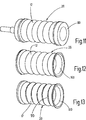
Ausführungsbeispiele des Erfindungsgegenstandes sind in der Zeichnung beispielsweise dargestellt und zwar zeigt:Exemplary embodiments of the subject invention are shown in the drawing, for example, and shows:
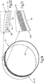
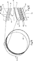
Jede Festigkeitsträgereinlage
Die bevorzugterweise eingesetzten Cord-Fäden
Nach einer weiteren Ausführungsform werden die Cord-Fäden
Die in Längsrichtung verlaufenden Fäden oder Fasern oder Cord-Fäden
Die Fixierfäden
Da es ausschließlich Aufgabe der Fixierfäden
Wird die Wand
Nach einer weiteren Ausführungsform sind die in Längsrichtung des Formkörpers
Zur Erhöhung der Festigkeit das Wellenbalges
Die Aufgabe der Ringkörper
Die gleiche Aufgabe, die die Ringkörper erfüllen, erfüllen die in das Material des Formkörpers
Das Bettungsmaterial
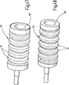
Der Formkörper
Die Fertigung eines Wellenbalges
Es wird zunächst ein streifenförmiger Innenliner
It is first a strip-shaped
Als nächster Schritt wird ein Flächengebilde
Die Verformung der einen oder mehreren Festigkeitsträgereinlagen
Die
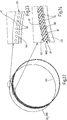
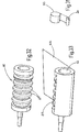
Eine weitere Fertigung eines Wellenbalges
Die
Der Aufbau des Rohlings
Der durch Extrusion erhaltene Rohling
Die
Der Formkörper
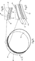
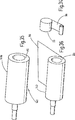
Eine Wellenbalg-Fertigung ist den
Der so vorbereitete Rohling
Der auf dem Kernwerkzeug
Die Länge der Profilrolle kann beliebig gewählt werden.
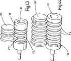
Eine weitere Ausführungsform einer Profilrolle
Bei der Ausführungsform eines Wellenbalges
Nach der Vulkanisierung wird der Presswickel oder Pressfolie und die Konturringe
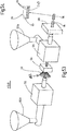
Ein Herstellungsverfahren für einen Wellenbalg
Der so erhaltene strangförmige Endlos-Rohling
Dieses Extrusionsverfahren hat den Vorteil, dass einerseits elastomere oder thermoplastische Kunststoffe verarbeitet werden, bei denen mit Hilfe der Extruder später formbare/vulkanisierbare Schlauchrohlinge vorbereitet werden, in die gleichzeitig die Cord-Fäden
Die Extrusionsanlage
Insofern ist die Extrusionsanlage
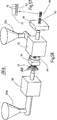
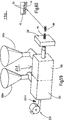
Ein weiteres Herstellungsverfahren für einen Wellenbalg
Der Grundaufbau der beiden Extrusionsanlagen
Der ersten Extruderringdüse
In
Die erhaltenen Rohlingsabschnitte
Mit der T-Co-Extrusionsanlage
BezugszeichenlisteLIST OF REFERENCE NUMBERS
- 100100
- Formwerkzeugmold
- 1010
- Formkörpermoldings
- 10a10a
- Rohlingblank
- 1111
- Wandflächewall surface
- 1212
- Wellenprofilwave profile
- 1313
- Längsachse WellenbalgLongitudinal axis bellows
- 14, 14a14, 14a
- Wellentälertroughs
- 1515
- Erhabener FormkörperabschnittSublime molded body section
- 2020
- Wellenbalgbellows
- 30, 30', 30a30, 30 ', 30a
- FestigkeitsträgereinlageStrength of reinforcement
- 4040
- Thermoplastthermoplastic
- 4545
- Bettungsmaterialbedding
- 5050
- Cord-FädenCord threads
- 6060
- Fixierfädenfixing threads
- 6161
- Reiheline
- 6262
- Reiheline
- 7070
- Ringkörperring body
- 8080
- Kernwerkzeugcore tool
- 8181
- Wellenprofilwave profile
- 8282
- Achse KernwerkzeugAxis core tool
- 8383
- Wellenprofilwave profile
- 9090
- Flächengebildesheet
- 9595
- Rollerole
- 9696
- Abschnittsection
- 9999
- Rohlingblank
- 101101
- Oberes WerkzeugUpper tool
- 102102
- Unteres WerkzeugLower tool
- 103a103a
- Formgebende FlächeShaping surface
- 103103
- Ober-/AußenformUpper / outer mold
- 104a104a
- Formgebende FlächeShaping surface
- 104104
- Unter-/InnenformUnder / inner mold
- 110110
- Strangstrand
- 111111
- Strangabschnittstrand section
- 115115
- Rohlingblank
- 116116
- Rohlingabschnittblank section
- 120 120
- Ringkörperring body
- 130, 130a130, 130a
- Extrusionsanlageextrusion plant
- 132132
- ExtruderringdüseExtruderringdüse
- 132a132a
- Materialtrichtermaterial hopper
- 133133
- Vorrichtungcontraption
- 134134
- Vorrichtungcontraption
- 135135
- ExtruderringdüseExtruderringdüse
- 135a135a
- Materialtrichtermaterial hopper
- 136136
- Vorrichtungcontraption
- 137137
- Vorrichtungcontraption
- 138138
- Weiterer ExtruderAnother extruder
- 140140
- Innenlinerinner liner
- 140a140a
- Streifenabschnittstrip section
- 141, 141a141, 141a
- Streifenabschnittstrip section
- 145145
- Rollerole
- 150150
- Profilrolleprofile role
- 151151
- Profilprofile
- 160160
- Rohlingblank
- 161161
- Zuführungfeed
- 170170
- T-Ko-ExtruderanlageT co-extrusion line
- 171171
- T-Ko-ExtruderT co-extruder
- 180180
- T-Ko-ExtruderanlageT co-extrusion line
- 181181
- T-Ko-ExtruderT co-extruder
- 190190
- Pressfoliepress sheet
ZITATE ENTHALTEN IN DER BESCHREIBUNG QUOTES INCLUDE IN THE DESCRIPTION
Diese Liste der vom Anmelder aufgeführten Dokumente wurde automatisiert erzeugt und ist ausschließlich zur besseren Information des Lesers aufgenommen. Die Liste ist nicht Bestandteil der deutschen Patent- bzw. Gebrauchsmusteranmeldung. Das DPMA übernimmt keinerlei Haftung für etwaige Fehler oder Auslassungen.This list of the documents listed by the applicant has been generated automatically and is included solely for the better information of the reader. The list is not part of the German patent or utility model application. The DPMA assumes no liability for any errors or omissions.
Zitierte PatentliteraturCited patent literature
- DE 202004018301 U1 [0002] DE 202004018301 U1 [0002]
- EP 1013979 B1 [0003] EP 1013979 B1 [0003]
Claims (16)
Applications Claiming Priority (2)
| Application Number | Priority Date | Filing Date | Title |
|---|---|---|---|
| EP12178108.2A EP2690335B1 (en) | 2012-07-26 | 2012-07-26 | Flexible, hose-shaped moulded body, such as bellows, and method for its manufacture |
| EP12178108.2 | 2012-07-26 |
Publications (1)
| Publication Number | Publication Date |
|---|---|
| DE202012103603U1 true DE202012103603U1 (en) | 2012-11-15 |
Family
ID=47426998
Family Applications (1)
| Application Number | Title | Priority Date | Filing Date |
|---|---|---|---|
| DE202012103603U Expired - Lifetime DE202012103603U1 (en) | 2012-07-26 | 2012-09-20 | Flexible, tubular shaped body, such as bellows |
Country Status (9)
| Country | Link |
|---|---|
| US (2) | US9188091B2 (en) |
| EP (1) | EP2690335B1 (en) |
| CN (1) | CN103574188B (en) |
| DE (1) | DE202012103603U1 (en) |
| ES (1) | ES2604936T3 (en) |
| HU (1) | HUE030230T2 (en) |
| PL (1) | PL2690335T3 (en) |
| PT (1) | PT2690335T (en) |
| RU (1) | RU2636521C2 (en) |
Cited By (3)
| Publication number | Priority date | Publication date | Assignee | Title |
|---|---|---|---|---|
| WO2014206979A1 (en) * | 2013-06-28 | 2014-12-31 | Bayerische Motoren Werke Aktiengesellschaft | Method and shaping tool for producing a fibre composite hollow component |
| WO2017025315A1 (en) * | 2015-08-12 | 2017-02-16 | Etm Engineering Technologie Marketing Gmbh | Air pipe for the intake tract of an internal combustion engine |
| CN115195151A (en) * | 2022-06-27 | 2022-10-18 | 华祥(中国)高纤有限公司 | Chemical fiber filament fiber composite production equipment and process |
Families Citing this family (14)
| Publication number | Priority date | Publication date | Assignee | Title |
|---|---|---|---|---|
| DE202012000553U1 (en) * | 2012-01-20 | 2012-03-15 | Boa Balg- Und Kompensatoren-Technologie Gmbh | Decoupling element for shielding structure-borne noise |
| DE102014011787A1 (en) * | 2014-08-12 | 2016-02-18 | Faserverbund Innovations UG (haftungsbeschränkt) | Resin pipe with flow aid |
| CN104482343B (en) * | 2014-12-12 | 2016-10-19 | 中国建筑标准设计研究院有限公司 | A kind of shock-insulation building flexibly connects the construction method of installation of pipeline |
| US10087821B2 (en) * | 2015-07-21 | 2018-10-02 | Garrett Transportation I Inc. | Turbocharger systems with direct turbine interfaces |
| US10087939B2 (en) * | 2015-07-21 | 2018-10-02 | Garrett Transportation I Inc. | Turbocharger systems with direct turbine interfaces |
| DE102016107504A1 (en) * | 2016-04-22 | 2017-10-26 | Ralph-Günther Matzen | Shaped body for directing air for an engine |
| WO2017205190A1 (en) | 2016-05-26 | 2017-11-30 | Corning Optical Communications LLC | Optical fiber cable with elongate strength member recessed in armor layer |
| JP1578318S (en) * | 2016-12-22 | 2017-06-05 | ||
| CN108262936B (en) * | 2016-12-31 | 2024-04-09 | 浙江双林机械股份有限公司 | Organ type pinch roller structure and working method |
| USD839402S1 (en) * | 2017-03-07 | 2019-01-29 | DooBon Flexible Co., LTD | Wrinkle tube for piping work |
| DE102018106319A1 (en) * | 2018-03-19 | 2019-09-19 | Bodo Richter | Method and plant for producing a single-walled or multi-walled tubular body of thermoplastic material |
| DE102018112488A1 (en) * | 2018-05-24 | 2019-11-28 | Mann+Hummel Gmbh | pipe component |
| KR102586935B1 (en) * | 2018-11-28 | 2023-10-11 | 현대자동차주식회사 | Manufacturing method of waterproof duct and waterproof duct thereby |
| CN110131498B (en) * | 2019-05-21 | 2020-09-29 | 三七知明(北京)科技有限公司 | Sealing device for butt joint of automobile corrugated pipes |
Citations (2)
| Publication number | Priority date | Publication date | Assignee | Title |
|---|---|---|---|---|
| EP1013979B1 (en) | 1998-12-22 | 2003-11-26 | Mündener Gummiwerk GmbH | Hose, for example for supply of air |
| DE202004018301U1 (en) | 2004-11-25 | 2005-08-18 | Veritas Ag | Flexible hose, in particular, for conduction of air to supercharged engines comprises embedded pressure carrier elements which are movable relative to the hose wall matrix at least within certain sections |
Family Cites Families (23)
| Publication number | Priority date | Publication date | Assignee | Title |
|---|---|---|---|---|
| BE561696A (en) * | ||||
| DE352812C (en) * | 1919-03-19 | 1922-05-04 | Blaisdell Petro Flex Tubing Co | Hose for petroleum, oil and like |
| US1535647A (en) * | 1919-12-18 | 1925-04-28 | Joseph B Brennan | Cord-tire stock and method of making same |
| US1648046A (en) * | 1921-05-26 | 1927-11-08 | Fulton Sylphon Co | Tubular corrugated wall and method of making the same |
| US1746701A (en) * | 1926-08-03 | 1930-02-11 | Goodyear Tire & Rubber | Flexible conduit and method of making the same |
| US2097862A (en) * | 1936-04-09 | 1937-11-02 | Boston Woven Hose & Rubber Co | Fire hose |
| US2143960A (en) * | 1937-06-14 | 1939-01-17 | Western Rubber Company | Nonkinking hose |
| US2299520A (en) * | 1940-02-28 | 1942-10-20 | Mine Safety Appliances Co | Method of making extensible conduit |
| US2312587A (en) * | 1941-12-29 | 1943-03-02 | Harry S Price | Tubular core |
| US3058493A (en) * | 1959-02-11 | 1962-10-16 | Porter Co Inc H K | Flexible reinforced corrugated hose |
| US3349806A (en) * | 1964-12-07 | 1967-10-31 | Fred T Roberts & Company | Reinforced hose construction and method of making the same |
| US4196031A (en) * | 1978-03-10 | 1980-04-01 | Titeflex Corporation | Method of making a preformed semirigid plastic hose wrapped with a wire spiral |
| SU910437A1 (en) * | 1980-02-08 | 1982-03-07 | Предприятие П/Я М-5064 | Unit for producing flexible hoses |
| DE4341383A1 (en) * | 1992-12-18 | 1994-06-23 | Volkswagen Ag | Convoluted flexible element for vehicle exhaust gas system |
| US5485870A (en) * | 1994-12-05 | 1996-01-23 | Kraik; Newell P. | Wire wrapped composite spiral hose and method |
| US6682796B2 (en) * | 2000-05-31 | 2004-01-27 | Tokai Rubber Industries, Ltd. | Fuel hose |
| JP2002106761A (en) * | 2000-10-04 | 2002-04-10 | Excel Kk | Bellows duct |
| EP1267111A1 (en) * | 2001-06-15 | 2002-12-18 | Dsm N.V. | Pressurized fluid conduit |
| US20040007278A1 (en) * | 2002-06-06 | 2004-01-15 | Williams Robert M. | Flexible conduit and method for forming the same |
| US7004201B2 (en) * | 2003-06-23 | 2006-02-28 | Tokai Rubber Industries, Ltd. | Vibration absorbing hose |
| US7891382B2 (en) * | 2005-12-16 | 2011-02-22 | Mercury Plastics, Inc. | Overmolded and bendable position-retaining tubing |
| CN201129564Y (en) * | 2007-12-14 | 2008-10-08 | 中国重汽集团济南技术中心有限公司 | Heavy-duty car intercooler novel silastic joint flexible pipe |
| CN201202925Y (en) * | 2008-06-29 | 2009-03-04 | 程秀萍 | Positive and negative pressure resistant polytetrafluorethylene compensator |
-
2012
- 2012-07-26 PL PL12178108T patent/PL2690335T3/en unknown
- 2012-07-26 ES ES12178108.2T patent/ES2604936T3/en active Active
- 2012-07-26 HU HUE12178108A patent/HUE030230T2/en unknown
- 2012-07-26 EP EP12178108.2A patent/EP2690335B1/en active Active
- 2012-07-26 PT PT121781082T patent/PT2690335T/en unknown
- 2012-08-23 RU RU2012136101A patent/RU2636521C2/en active
- 2012-08-23 US US13/592,860 patent/US9188091B2/en active Active
- 2012-09-20 DE DE202012103603U patent/DE202012103603U1/en not_active Expired - Lifetime
- 2012-11-02 CN CN201210434015.XA patent/CN103574188B/en active Active
-
2015
- 2015-11-16 US US14/942,112 patent/US20160059463A1/en not_active Abandoned
Patent Citations (2)
| Publication number | Priority date | Publication date | Assignee | Title |
|---|---|---|---|---|
| EP1013979B1 (en) | 1998-12-22 | 2003-11-26 | Mündener Gummiwerk GmbH | Hose, for example for supply of air |
| DE202004018301U1 (en) | 2004-11-25 | 2005-08-18 | Veritas Ag | Flexible hose, in particular, for conduction of air to supercharged engines comprises embedded pressure carrier elements which are movable relative to the hose wall matrix at least within certain sections |
Cited By (5)
| Publication number | Priority date | Publication date | Assignee | Title |
|---|---|---|---|---|
| WO2014206979A1 (en) * | 2013-06-28 | 2014-12-31 | Bayerische Motoren Werke Aktiengesellschaft | Method and shaping tool for producing a fibre composite hollow component |
| WO2017025315A1 (en) * | 2015-08-12 | 2017-02-16 | Etm Engineering Technologie Marketing Gmbh | Air pipe for the intake tract of an internal combustion engine |
| US10731610B2 (en) | 2015-08-12 | 2020-08-04 | ETM Engineering Technologies Marketing GmbH | Air pipe for the intake tract of an internal combustion engine |
| CN115195151A (en) * | 2022-06-27 | 2022-10-18 | 华祥(中国)高纤有限公司 | Chemical fiber filament fiber composite production equipment and process |
| CN115195151B (en) * | 2022-06-27 | 2023-11-14 | 华祥(中国)高纤有限公司 | Chemical fiber and fiber composite production equipment and process |
Also Published As
| Publication number | Publication date |
|---|---|
| US20160059463A1 (en) | 2016-03-03 |
| RU2012136101A (en) | 2014-02-27 |
| PT2690335T (en) | 2016-12-14 |
| EP2690335B1 (en) | 2016-08-31 |
| US20140027001A1 (en) | 2014-01-30 |
| PL2690335T3 (en) | 2017-03-31 |
| RU2636521C2 (en) | 2017-11-23 |
| HUE030230T2 (en) | 2017-04-28 |
| EP2690335A1 (en) | 2014-01-29 |
| ES2604936T3 (en) | 2017-03-10 |
| US9188091B2 (en) | 2015-11-17 |
| CN103574188A (en) | 2014-02-12 |
| CN103574188B (en) | 2018-09-18 |
Similar Documents
| Publication | Publication Date | Title |
|---|---|---|
| EP2690335B1 (en) | Flexible, hose-shaped moulded body, such as bellows, and method for its manufacture | |
| DE60302302T2 (en) | Lead for a ventilation circuit | |
| DE112011105852B4 (en) | Protective cover and method of making same | |
| DE202017101198U1 (en) | Casting tool for producing belts for the transmission of kinetic energy | |
| DE3401016A1 (en) | BELT TIRES AND METHOD FOR PRODUCING THE SAME | |
| DE102011104071A1 (en) | Method for manufacturing leaf spring that is utilized for function integration of e.g. axle to vehicle, involves melting matrix material in prepeg tape by concentrated introduction of heat when prepeg band is impinged on mold | |
| DE102008055480A1 (en) | Flexible hose for high pressures and temperatures, in particular charge air or cooling water hose | |
| EP0350732B1 (en) | Drawn formed tow | |
| DE102007061735A1 (en) | Toothed belt for synchronous belt drive placed in the interior of crank case of internal combustion engine of motor vehicle, has tooth side, rear side opposite to tooth side, elastomer material, tensile strand, fabric layers, and coating | |
| DE2261126A1 (en) | HOSE AND PROCESS FOR ITS MANUFACTURING | |
| DE2818786C2 (en) | Method of making an endless, toothless power transmission belt | |
| DE1806076A1 (en) | Flexible, continuous mandrel for the manufacture of hoses and process for their manufacture | |
| EP1013979B1 (en) | Hose, for example for supply of air | |
| EP2991786B1 (en) | Method for producing a shaped wire element from a wire mesh, and a shaped wire element | |
| DE19612196C2 (en) | Method and device for manufacturing composite insulators | |
| DE112017001731T5 (en) | Method of manufacturing a belt and two-layer bonding machine | |
| EP2962028B1 (en) | Knitted heat-shrink tube and method for producing same | |
| DE1927042C3 (en) | Process for the production of conveyor belts or drive belts from thread-reinforced thermoplastic or from rubber | |
| DE10162294B4 (en) | Process for the production of elbow hoses | |
| DE102008058741B4 (en) | Method and device for producing a curved molding tube | |
| DE2543579A1 (en) | ROLLER COVER AND PROCESS FOR ITS MANUFACTURING | |
| DE112019000546T5 (en) | Method of manufacturing a power transmission belt | |
| DE202016102151U1 (en) | Shaped body for directing air for an engine | |
| WO2017182328A1 (en) | Molded body for conducting air for a motor | |
| EP3498449B1 (en) | Method for manufacturing an air conditioning hose and device for performing the method |
Legal Events
| Date | Code | Title | Description |
|---|---|---|---|
| R207 | Utility model specification |
Effective date: 20130110 |
|
| R150 | Utility model maintained after payment of first maintenance fee after three years | ||
| R151 | Utility model maintained after payment of second maintenance fee after six years | ||
| R158 | Lapse of ip right after 8 years |