DE202008009891U1 - Gear stage for an actuator - Google Patents
Gear stage for an actuator Download PDFInfo
- Publication number
- DE202008009891U1 DE202008009891U1 DE202008009891U DE202008009891U DE202008009891U1 DE 202008009891 U1 DE202008009891 U1 DE 202008009891U1 DE 202008009891 U DE202008009891 U DE 202008009891U DE 202008009891 U DE202008009891 U DE 202008009891U DE 202008009891 U1 DE202008009891 U1 DE 202008009891U1
- Authority
- DE
- Germany
- Prior art keywords
- drive
- pinion
- axis
- gear stage
- rotation
- Prior art date
- Legal status (The legal status is an assumption and is not a legal conclusion. Google has not performed a legal analysis and makes no representation as to the accuracy of the status listed.)
- Expired - Lifetime
Links
Classifications
-
- F—MECHANICAL ENGINEERING; LIGHTING; HEATING; WEAPONS; BLASTING
- F16—ENGINEERING ELEMENTS AND UNITS; GENERAL MEASURES FOR PRODUCING AND MAINTAINING EFFECTIVE FUNCTIONING OF MACHINES OR INSTALLATIONS; THERMAL INSULATION IN GENERAL
- F16H—GEARING
- F16H1/00—Toothed gearings for conveying rotary motion
- F16H1/28—Toothed gearings for conveying rotary motion with gears having orbital motion
- F16H1/32—Toothed gearings for conveying rotary motion with gears having orbital motion in which the central axis of the gearing lies inside the periphery of an orbital gear
-
- B—PERFORMING OPERATIONS; TRANSPORTING
- B60—VEHICLES IN GENERAL
- B60N—SEATS SPECIALLY ADAPTED FOR VEHICLES; VEHICLE PASSENGER ACCOMMODATION NOT OTHERWISE PROVIDED FOR
- B60N2/00—Seats specially adapted for vehicles; Arrangement or mounting of seats in vehicles
- B60N2/02—Seats specially adapted for vehicles; Arrangement or mounting of seats in vehicles the seat or part thereof being movable, e.g. adjustable
- B60N2/22—Seats specially adapted for vehicles; Arrangement or mounting of seats in vehicles the seat or part thereof being movable, e.g. adjustable the back-rest being adjustable
- B60N2/225—Seats specially adapted for vehicles; Arrangement or mounting of seats in vehicles the seat or part thereof being movable, e.g. adjustable the back-rest being adjustable by cycloidal or planetary mechanisms
- B60N2/2252—Seats specially adapted for vehicles; Arrangement or mounting of seats in vehicles the seat or part thereof being movable, e.g. adjustable the back-rest being adjustable by cycloidal or planetary mechanisms in which the central axis of the gearing lies inside the periphery of an orbital gear, e.g. one gear without sun gear
Landscapes
- Engineering & Computer Science (AREA)
- Mechanical Engineering (AREA)
- General Engineering & Computer Science (AREA)
- Aviation & Aerospace Engineering (AREA)
- Transportation (AREA)
- Retarders (AREA)
- Gear Transmission (AREA)
- Rolling Contact Bearings (AREA)
Abstract
Getriebestufe
(10) für einen Stellantrieb in einem Fahrzeug, insbesondere
eines Fahrzeugsitzes (2), mit
a) einem Antrieb (11), welcher
um eine Drehachse (A) drehbar ist,
b) wenigstens einem Exzenter
(12), welcher eine zur Drehachse (A) parallel um eine Exzentrizität
(e) versetzte Exzenterachse (B) und eine der Exzenterachse (B) bezüglich der
Drehachse (A) gegenüberliegende Engstelle (H) definiert,
wenigstens einen Wälzkörper (12a, 12b) aufweist
und vom Antrieb (11) angetrieben wird,
c) einem Ritzel (14),
welches vom Exzenter (12) angetrieben wird,
d) einem Hohlrad
(16), relativ zu welchem das Ritzel (14) eine einen Wälzkontakt
(W) definierende Abwälzbewegung ausführt, und
e)
einem Abtrieb (18), welcher die relative Abwälzbewegung
von Ritzel (14) und Hohlrad (16) abgreift,
dadurch gekennzeichnet,
dass
f) der Exzenter (12) als Wälzkörper
(12a, 12b) wenigstens zwei Antriebskörper (12b), welche
das Antriebsmoment für den Antrieb des Ritzels (14) aufbringen,
und wenigstens einen Stützkörper (12a) aufweist,
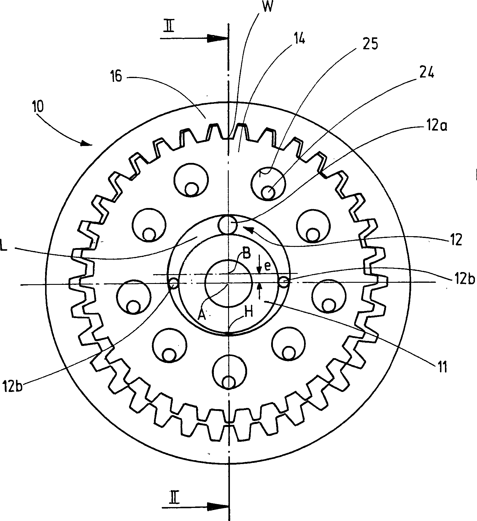
welcher wenigstens...Gear stage (10) for an actuator in a vehicle, in particular a vehicle seat (2), with
a) a drive (11) which is rotatable about a rotation axis (A),
b) at least one eccentric (12) which defines an eccentric axis (B) offset parallel to the axis of rotation (A) by an eccentricity (e) and a constriction (H) opposite the eccentric axis (B) with respect to the axis of rotation (A), at least one Rolling body (12a, 12b) and is driven by the drive (11),
c) a pinion (14), which is driven by the eccentric (12),
d) a ring gear (16) relative to which the pinion (14) executes a rolling contact (W) defining rolling movement, and
e) an output (18), which picks up the relative rolling movement of pinion (14) and ring gear (16),
characterized in that
f) the eccentric (12) as a rolling body (12a, 12b) at least two drive body (12b) which apply the drive torque for driving the pinion (14), and at least one support body (12a), which at least ...
Description
Die Erfindung betrifft eine Getriebestufe für einen Stellantrieb, insbesondere eines Fahrzeugsitzes, mit den Merkmalen des Oberbegriffs des Anspruches 1.The Invention relates to a gear stage for an actuator, in particular a vehicle seat, having the features of the preamble of claim 1.
Aus
der
Der Erfindung liegt die Aufgabe zu Grunde, eine Getriebestufe der eingangs genannten Art zu verbessern. Diese Aufgabe wird erfindungsgemäß durch eine Getriebestufe mit den Merkmalen des Anspruches 1 gelöst. Vorteilhafte Ausgestaltungen sind Gegenstand der Unteransprüche.Of the Invention is based on the object, a gear stage of the beginning to improve the type mentioned. This object is achieved by a gear stage with the features of claim 1 solved. Advantageous embodiments are the subject of the dependent claims.
Dadurch, dass der Exzenter als Wälzkörper wenigstens zwei Antriebskörper, welche das Antriebsmoment für den Antrieb des Ritzels aufbringen, und wenigstens einen Stützkörper aufweist, welcher wenigstens zwischen der Drehachse und dem Wälzkontakt angeordnet ist, die weiteste Stelle eines sichelförmigen Luftspaltes zwischen Antrieb und Ritzel ausfüllt und der Abstützung des Ritzels dient, erfolgt eine Funktionsaufteilung von radialem Stützen und Antreiben auf die verschiedenen Wälzkörper. Entsprechend diesen Funktionen sind die einzelnen Wälzkörper an bevorzugten Stellen des Exzenters angeordnet und bewegen sich auf vorbestimmten Bahnen, beispielsweise um den Wirkungsgrad der Getriebestufe zu verbessern und/oder einen Leerweg beim Starten oder bei einer Umkehr der Drehrichtung zu vermeiden. Mit dem gleichen Ziel können auch bestimmten Größenverhältnisse ge wählt werden. Rillenartige oder nutartige Laufbahnen können eine gute Schmiegung und/oder gezielte Änderungen der Bahnen der Wälzkörper bewirken.Thereby, that the eccentric as rolling elements at least two Drive body which the drive torque for apply the drive of the pinion, and at least one support body which has at least between the axis of rotation and the rolling contact is arranged, the furthest point of a crescent-shaped Air gap between drive and pinion fills and the Supporting the pinion, there is a function distribution of radial props and driving on the different ones Rolling elements. According to these functions are the individual rolling elements at preferred locations arranged on the eccentric and move on predetermined paths, for example, to improve the efficiency of the gear stage and / or a free path when starting or reversing the direction of rotation to avoid. With the same goal can also be specific Size ratios ge be selected. Grooved or groove-like tracks can be a good Oscillation and / or targeted changes of the tracks of the Cause rolling elements.
Für
das Abgreifen der Abwälzbewegung durch den Abtrieb ist
vorzugsweise ein Kreisschubgetriebe (Flächendruckgetriebe)
mit Führungselementen für das Ritzel vorgesehen,
wie es beispielsweise in der
Es ist für den laufenden Betrieb, auch hinsichtlich lokaler Belastungen und Verschleiß, von Vorteil, wenn funktionsbedingte Exzentrizitäten der Bewegung und Unsymmetrien der Lagerkräfte möglichst weitgehend kompensiert werden. So kann eine Kompensation des taumelnden Anteils der Abwälzbewegung beim Übergang auf den Abtrieb durch ein Kreisschubgetriebe oder eine Kompensationsstufe mit einer Übersetzung von eins erfolgen. Insbesondere beim Kreisschubgetriebe kann eine näherungsweise symmetrische Beaufschlagung des Abtriebs erfolgen, indem zwei Ritzel bezüglich der Drehachse exzentrisch, in Umfangsrichtung um 180° versetzt zueinander und axial nebeneinander gelagert sind und mit dem gemeinsamen Hohlrad und gemeinsamen Abtrieb zusammenwirken.It is for ongoing operation, also local Loads and wear, beneficial if functional Eccentricities of movement and asymmetry of the bearing forces be compensated as much as possible. So can a compensation the tumbling portion of the rolling motion at the transition on the output by a circular push gear or a compensation stage with a translation of one. Especially when Circular push gear can be an approximately symmetrical Actuation of the output can be done by two pinions with respect to the axis of rotation eccentric, offset in the circumferential direction by 180 ° to each other and axially adjacent to each other and with the common ring gear and common output interact.
Um eine stärkere Untersetzung von der Motordrehzahl in die Drehzahl des Abtriebs zu erreichen, können zwei Getriebestufen in Serie geschaltet werden, wobei die zwei Getriebestufen axial und/oder radial geschachtelt sein können. Gleichachsige Drehungen des Antriebs und Abtriebs der Getriebestufen benötigen keine Ausgleichselemente und ermöglichen einfache Lagerverhältnisse.Around a stronger reduction of the engine speed in the To achieve the speed of the output, two gear stages be connected in series, the two gear stages axially and / or can be nested radially. Equiaxial turns the drive and output of the gear stages need No compensation elements and allow easy storage conditions.
Die erfindungsgemäße Getriebestufe kann mit einem bürsten- oder elektronisch kommutierten Motor, an den sie abtriebsseitig angeschlossen wird, zu einem motorischen Stellantrieb kombiniert werden. Ein vorzugsweise gemeinsames Gehäuse des motorischen Stellantriebs kann, gegebenenfalls unter Hinzunahme von Deckeln oder dergleichen, abdichtend aufgebaut werden, was eine problemlose Behandlung des motorischen Stellantriebs in einem Tauchbad erlaubt.The Gear stage according to the invention can with a brush or electronically commutated motor to which they connected on the output side, to a motorized actuator be combined. A preferably common housing of the motorized actuator can, if necessary, with addition of lids or the like, are sealingly constructed, which is a easy handling of the motorized actuator in a dipping bath allowed.
Ein solcher motorischer Stellantrieb kann beispielsweise in ein lastaufnehmendes Getriebe eines Einstellers eines Fahrzeugsitzes integriert werden. Aufgrund der hohen Untersetzung kann, falls notwendig, ein Ablaufen des lastaufnehmenden Getriebes durch eine Schlingfederbremse oder dergleichen am Rotor des Motors verhindert werden. Eine Hohlwellenbauweise erlaubt einen einfachen Anschluss einer Übertragungsstange zwischen beiden Fahrzeugsitzseiten, vorzugsweise durch eine profilierte zentrale Aufnahme in dem Antriebsbauteil für das lastaufnehmende Getriebe, also vorliegend im Abtrieb der Getriebstufe.One such motorized actuator can, for example, in a lastaufnehmendes Gearbox of an adjuster of a vehicle seat can be integrated. Due to the high reduction, it can, if necessary, drain of the load-bearing transmission by a wrap spring brake or the like can be prevented on the rotor of the motor. A hollow shaft design allows easy connection of a transmission rod between the two vehicle seat sides, preferably by a profiled Central receptacle in the drive member for the load-bearing Transmission, in this case in the output of the gear stage.
Im folgenden ist die Erfindung anhand eines in der Zeichnung dargestellten Ausführungsbeispiels näher erläutert. Es zeigenin the The following is the invention with reference to an illustrated in the drawing Embodiment explained in more detail. Show it
Ein
motorischer Stellantrieb
Das
Ritzel
Bezüglich
des Abtriebs
Der
Exzenter
Soweit
stimmen die beiden Ausführungsbeispiele überein.
Unterschiede sind in der genauen Ausbildung des Exzenters
Im
Ausführungsbeispiel ist eine große Kugel als Stützkörper
Wird
der Antrieb
Der
sich drehende Exzenter
In
Folge des aufgebrachten Moments ist das Ritzel
Der
in Drehrichtung nacheilende Antriebskörper
Damit
die Getriebestufe
Der
erfindungsgemäße motorische Stellantrieb
Der
motorische Stellantrieb
- 11
- motorischer Stellantriebmotorized actuator
- 22
- Fahrzeugsitzvehicle seat
- 55
- Motorengine
- 1010
- Getriebestufegear stage
- 1111
- Antriebdrive
- 1212
- Exzentereccentric
- 12a12a
- Stützkörpersupport body
- 12b12b
- Antriebskörperdrive body
- 1414
- Ritzelpinion
- 1616
- Hohlradring gear
- 1818
- Abtrieboutput
- 2424
- Führungselementguide element
- 2525
- Führungsöffnungguide opening
- 4242
- Lehnerest
- 4343
- Sitzteilseat part
- AA
- Drehachseaxis of rotation
- BB
- Exzenterachseeccentric
- ee
- Exzentrizitäteccentricity
- HH
- Engstellebottleneck
- LL
- Luftspaltair gap
- WW
- Wälzkontaktrolling contact
ZITATE ENTHALTEN IN DER BESCHREIBUNGQUOTES INCLUDE IN THE DESCRIPTION
Diese Liste der vom Anmelder aufgeführten Dokumente wurde automatisiert erzeugt und ist ausschließlich zur besseren Information des Lesers aufgenommen. Die Liste ist nicht Bestandteil der deutschen Patent- bzw. Gebrauchsmusteranmeldung. Das DPMA übernimmt keinerlei Haftung für etwaige Fehler oder Auslassungen.This list The documents listed by the applicant have been automated generated and is solely for better information recorded by the reader. The list is not part of the German Patent or utility model application. The DPMA takes over no liability for any errors or omissions.
Zitierte PatentliteraturCited patent literature
- - DE 10232247 B3 [0002] DE 10232247 B3 [0002]
- - US 4228698 A [0005] - US 4228698 A [0005]
- - EP 0450324 B1 [0005] - EP 0450324 B1 [0005]
- - DE 19938666 A1 [0026] - DE 19938666 A1 [0026]
- - DE 102004019466 A1 [0026] DE 102004019466 A1 [0026]
Claims (10)
Priority Applications (1)
| Application Number | Priority Date | Filing Date | Title |
|---|---|---|---|
| DE202008009891U DE202008009891U1 (en) | 2007-09-05 | 2008-07-21 | Gear stage for an actuator |
Applications Claiming Priority (3)
| Application Number | Priority Date | Filing Date | Title |
|---|---|---|---|
| DE200710042168 DE102007042168B4 (en) | 2007-09-05 | 2007-09-05 | Gear stage for an actuator |
| DE102007042168.2 | 2007-09-05 | ||
| DE202008009891U DE202008009891U1 (en) | 2007-09-05 | 2008-07-21 | Gear stage for an actuator |
Publications (1)
| Publication Number | Publication Date |
|---|---|
| DE202008009891U1 true DE202008009891U1 (en) | 2008-10-09 |
Family
ID=39829894
Family Applications (2)
| Application Number | Title | Priority Date | Filing Date |
|---|---|---|---|
| DE200710042168 Expired - Fee Related DE102007042168B4 (en) | 2007-09-05 | 2007-09-05 | Gear stage for an actuator |
| DE202008009891U Expired - Lifetime DE202008009891U1 (en) | 2007-09-05 | 2008-07-21 | Gear stage for an actuator |
Family Applications Before (1)
| Application Number | Title | Priority Date | Filing Date |
|---|---|---|---|
| DE200710042168 Expired - Fee Related DE102007042168B4 (en) | 2007-09-05 | 2007-09-05 | Gear stage for an actuator |
Country Status (1)
| Country | Link |
|---|---|
| DE (2) | DE102007042168B4 (en) |
Cited By (3)
| Publication number | Priority date | Publication date | Assignee | Title |
|---|---|---|---|---|
| WO2010105737A1 (en) * | 2009-03-19 | 2010-09-23 | Keiper Gmbh & Co. Kg | Drive device for a motor vehicle seat |
| DE112013003092B4 (en) * | 2012-06-19 | 2020-09-24 | Faurecia Sièges d'Automobile | Drive module for a vehicle seat, adjusting mechanism and seat for a motor vehicle |
| CN116804427A (en) * | 2022-03-25 | 2023-09-26 | 现代坦迪斯株式会社 | Motor speed reducer |
Citations (5)
| Publication number | Priority date | Publication date | Assignee | Title |
|---|---|---|---|---|
| US4228698A (en) | 1978-05-08 | 1980-10-21 | Winiasz Michael E | Speed reducer |
| EP0450324B1 (en) | 1990-03-16 | 1994-07-20 | C. Rob. Hammerstein GmbH | Rocking gearing for an adjustable vehicle seat |
| DE19938666A1 (en) | 1999-08-14 | 2001-02-22 | Keiper Gmbh & Co | Adjustment fitting for seats with reclining backrest, especially for motor vehicle seats |
| DE10232247B3 (en) | 2002-07-17 | 2004-03-04 | Bühler Motor GmbH | Eccentric gear used as a rolling eccentric gear comprises a sun wheel, a planet wheel rolling on the inner side of an external geared wheel, and an internal geared wheel |
| DE102004019466A1 (en) | 2004-04-15 | 2005-11-10 | Keiper Gmbh & Co.Kg | Adjuster for a vehicle seat |
Family Cites Families (8)
| Publication number | Priority date | Publication date | Assignee | Title |
|---|---|---|---|---|
| US1194288A (en) * | 1916-08-08 | Mechanical movement | ||
| GB600885A (en) * | 1945-11-22 | 1948-04-21 | Francesco Cigogna | Improvements in or relating to speed reduction gear |
| FR601616A (en) * | 1924-11-04 | 1926-03-05 | Roller or ball speed reducer or multiplier system | |
| BE359150A (en) * | 1928-03-19 | |||
| US3602070A (en) * | 1970-04-10 | 1971-08-31 | Bendix Corp | Mechanical transmission |
| DE10134355B4 (en) * | 2001-07-14 | 2005-10-13 | Faurecia Autositze Gmbh & Co. Kg | Adjustment fitting for motor vehicle seats |
| DE102006005906A1 (en) * | 2005-08-23 | 2007-08-30 | Keiper Gmbh & Co.Kg | gear stage |
| DE102006023535B4 (en) * | 2006-05-19 | 2008-12-18 | Keiper Gmbh & Co.Kg | Gear stage for an actuator |
-
2007
- 2007-09-05 DE DE200710042168 patent/DE102007042168B4/en not_active Expired - Fee Related
-
2008
- 2008-07-21 DE DE202008009891U patent/DE202008009891U1/en not_active Expired - Lifetime
Patent Citations (5)
| Publication number | Priority date | Publication date | Assignee | Title |
|---|---|---|---|---|
| US4228698A (en) | 1978-05-08 | 1980-10-21 | Winiasz Michael E | Speed reducer |
| EP0450324B1 (en) | 1990-03-16 | 1994-07-20 | C. Rob. Hammerstein GmbH | Rocking gearing for an adjustable vehicle seat |
| DE19938666A1 (en) | 1999-08-14 | 2001-02-22 | Keiper Gmbh & Co | Adjustment fitting for seats with reclining backrest, especially for motor vehicle seats |
| DE10232247B3 (en) | 2002-07-17 | 2004-03-04 | Bühler Motor GmbH | Eccentric gear used as a rolling eccentric gear comprises a sun wheel, a planet wheel rolling on the inner side of an external geared wheel, and an internal geared wheel |
| DE102004019466A1 (en) | 2004-04-15 | 2005-11-10 | Keiper Gmbh & Co.Kg | Adjuster for a vehicle seat |
Cited By (6)
| Publication number | Priority date | Publication date | Assignee | Title |
|---|---|---|---|---|
| WO2010105737A1 (en) * | 2009-03-19 | 2010-09-23 | Keiper Gmbh & Co. Kg | Drive device for a motor vehicle seat |
| CN102292239A (en) * | 2009-03-19 | 2011-12-21 | 凯珀两合公司 | drive device for a motor vehicle seat |
| US8579377B2 (en) | 2009-03-19 | 2013-11-12 | Keiper Gmbh & Co. Kg | Device for a motor vehicle seat |
| CN102292239B (en) * | 2009-03-19 | 2014-08-20 | 凯珀两合公司 | Drive device for a motor vehicle seat |
| DE112013003092B4 (en) * | 2012-06-19 | 2020-09-24 | Faurecia Sièges d'Automobile | Drive module for a vehicle seat, adjusting mechanism and seat for a motor vehicle |
| CN116804427A (en) * | 2022-03-25 | 2023-09-26 | 现代坦迪斯株式会社 | Motor speed reducer |
Also Published As
| Publication number | Publication date |
|---|---|
| DE102007042168B4 (en) | 2009-11-19 |
| DE102007042168A1 (en) | 2009-03-26 |
Similar Documents
| Publication | Publication Date | Title |
|---|---|---|
| DE19708293B4 (en) | vehicle transmissions | |
| DE69919135T2 (en) | STARTER FOR MOTOR VEHICLE WITH GEARBOX WITH TORSION DAMPING FORMATS | |
| EP2100056A1 (en) | Transmission | |
| WO2007134705A2 (en) | Gear train for an actuator | |
| WO2008077676A1 (en) | Mounting arrangement of a shaft | |
| DE102008053914A1 (en) | Wave generator for a stress wave transmission and stress wave transmission | |
| DE102019205760A1 (en) | Lubricator and planetary gear and motor vehicle | |
| DE102012210169A1 (en) | Eccentric gear for use as control gear in e.g. industrial robot, has planetary axle arranged in planetary carrier, and drive part including eccentric sleeve with eccentric part, where eccentric sleeve is rotatably mounted in carrier | |
| EP3751174A1 (en) | Adjustment drive | |
| DE102016205748B3 (en) | actuating mechanism | |
| EP0949419A1 (en) | Internal gear pump | |
| EP3324076B1 (en) | Rolling bearing transmission | |
| EP2255104B1 (en) | Transmission | |
| DE102007042168B4 (en) | Gear stage for an actuator | |
| DE1182011B (en) | Gearbox with several toothed wheels | |
| DE102006005906A1 (en) | gear stage | |
| EP1910707B1 (en) | Actuator for units comprising a planetary gear | |
| WO2010009697A1 (en) | Drive system for an infinitely variable transmission of a motor vehicle | |
| WO1997025554A2 (en) | Device for conversion of rotary into axial movement | |
| DE102006057482A1 (en) | Shift release clutch for a manual transmission | |
| WO2012139674A1 (en) | Gearing mechanism | |
| DE102011016991A1 (en) | Device for adjusting transmission ratio of crank continuously variable transmission, has drive shaft connected with driven shaft of freewheel, and main connecting rod actively connected with drive shaft and outer ring of freewheel | |
| DE102009024348A1 (en) | Bearing arrangement for the wheel hub of a motor vehicle comprises a rolling body with rolling bearings formed as rollers each having two side surfaces flattened symmetrically by a ball base and arranged parallel to each other | |
| DE602005004106T2 (en) | Device for starting an internal combustion engine | |
| DE102007048128A1 (en) | Shifted gear for motor control drive in vehicle, particularly vehicle seat, has drive, which is rotating around axis of rotation, and intermediate element is provided |
Legal Events
| Date | Code | Title | Description |
|---|---|---|---|
| R207 | Utility model specification |
Effective date: 20081113 |
|
| R150 | Utility model maintained after payment of first maintenance fee after three years | ||
| R150 | Utility model maintained after payment of first maintenance fee after three years |
Effective date: 20111130 |
|
| R081 | Change of applicant/patentee |
Owner name: ADIENT LUXEMBOURG HOLDING S.A.R.L., LU Free format text: FORMER OWNER: KEIPER GMBH & CO. KG, 67657 KAISERSLAUTERN, DE Effective date: 20140626 Owner name: JOHNSON CONTROLS COMPONENTS GMBH & CO. KG, DE Free format text: FORMER OWNER: KEIPER GMBH & CO. KG, 67657 KAISERSLAUTERN, DE Effective date: 20140626 Owner name: ADIENT LUXEMBOURG HOLDING S.A R.L., LU Free format text: FORMER OWNER: KEIPER GMBH & CO. KG, 67657 KAISERSLAUTERN, DE Effective date: 20140626 |
|
| R151 | Utility model maintained after payment of second maintenance fee after six years | ||
| R151 | Utility model maintained after payment of second maintenance fee after six years |
Effective date: 20140807 |
|
| R152 | Utility model maintained after payment of third maintenance fee after eight years | ||
| R081 | Change of applicant/patentee |
Owner name: ADIENT LUXEMBOURG HOLDING S.A.R.L., LU Free format text: FORMER OWNER: JOHNSON CONTROLS COMPONENTS GMBH & CO. KG, 67657 KAISERSLAUTERN, DE Owner name: ADIENT LUXEMBOURG HOLDING S.A R.L., LU Free format text: FORMER OWNER: JOHNSON CONTROLS COMPONENTS GMBH & CO. KG, 67657 KAISERSLAUTERN, DE |
|
| R081 | Change of applicant/patentee |
Owner name: ADIENT LUXEMBOURG HOLDING S.A R.L., LU Free format text: FORMER OWNER: ADIENT LUXEMBOURG HOLDING S.A.R.L., LUXEMBOURG, LU |
|
| R071 | Expiry of right |