DE19911368B4 - Apparatus for producing sprayed mortar for use in wet spraying - Google Patents
Apparatus for producing sprayed mortar for use in wet spraying Download PDFInfo
- Publication number
- DE19911368B4 DE19911368B4 DE19911368A DE19911368A DE19911368B4 DE 19911368 B4 DE19911368 B4 DE 19911368B4 DE 19911368 A DE19911368 A DE 19911368A DE 19911368 A DE19911368 A DE 19911368A DE 19911368 B4 DE19911368 B4 DE 19911368B4
- Authority
- DE
- Germany
- Prior art keywords
- mixing
- pipe section
- mortar
- stage
- tube
- Prior art date
- Legal status (The legal status is an assumption and is not a legal conclusion. Google has not performed a legal analysis and makes no representation as to the accuracy of the status listed.)
- Expired - Fee Related
Links
- 239000004570 mortar (masonry) Substances 0.000 title claims abstract description 56
- 238000005507 spraying Methods 0.000 title claims abstract description 10
- 238000002156 mixing Methods 0.000 claims abstract description 103
- XLYOFNOQVPJJNP-UHFFFAOYSA-N water Substances O XLYOFNOQVPJJNP-UHFFFAOYSA-N 0.000 claims abstract description 18
- 238000003860 storage Methods 0.000 claims abstract description 6
- 238000004519 manufacturing process Methods 0.000 abstract description 7
- 239000007921 spray Substances 0.000 abstract description 3
- 238000000034 method Methods 0.000 description 7
- 238000003823 mortar mixing Methods 0.000 description 6
- 239000006185 dispersion Substances 0.000 description 5
- 229910052500 inorganic mineral Inorganic materials 0.000 description 4
- 239000011707 mineral Substances 0.000 description 4
- 239000000203 mixture Substances 0.000 description 4
- 239000000463 material Substances 0.000 description 3
- 229910000831 Steel Inorganic materials 0.000 description 1
- 239000000654 additive Substances 0.000 description 1
- 230000004323 axial length Effects 0.000 description 1
- 230000015572 biosynthetic process Effects 0.000 description 1
- 239000011083 cement mortar Substances 0.000 description 1
- 238000010924 continuous production Methods 0.000 description 1
- 230000018109 developmental process Effects 0.000 description 1
- 238000004090 dissolution Methods 0.000 description 1
- 239000000428 dust Substances 0.000 description 1
- 238000012423 maintenance Methods 0.000 description 1
- 230000002093 peripheral effect Effects 0.000 description 1
- 230000002250 progressing effect Effects 0.000 description 1
- 239000010959 steel Substances 0.000 description 1
- 238000003756 stirring Methods 0.000 description 1
Images
Classifications
-
- B—PERFORMING OPERATIONS; TRANSPORTING
- B28—WORKING CEMENT, CLAY, OR STONE
- B28C—PREPARING CLAY; PRODUCING MIXTURES CONTAINING CLAY OR CEMENTITIOUS MATERIAL, e.g. PLASTER
- B28C5/00—Apparatus or methods for producing mixtures of cement with other substances, e.g. slurries, mortars, porous or fibrous compositions
- B28C5/08—Apparatus or methods for producing mixtures of cement with other substances, e.g. slurries, mortars, porous or fibrous compositions using driven mechanical means affecting the mixing
- B28C5/10—Mixing in containers not actuated to effect the mixing
- B28C5/12—Mixing in containers not actuated to effect the mixing with stirrers sweeping through the materials, e.g. with incorporated feeding or discharging means or with oscillating stirrers
- B28C5/14—Mixing in containers not actuated to effect the mixing with stirrers sweeping through the materials, e.g. with incorporated feeding or discharging means or with oscillating stirrers the stirrers having motion about a horizontal or substantially horizontal axis
- B28C5/145—Mixing in containers not actuated to effect the mixing with stirrers sweeping through the materials, e.g. with incorporated feeding or discharging means or with oscillating stirrers the stirrers having motion about a horizontal or substantially horizontal axis with several mixing chambers arranged one after the other
-
- B—PERFORMING OPERATIONS; TRANSPORTING
- B01—PHYSICAL OR CHEMICAL PROCESSES OR APPARATUS IN GENERAL
- B01F—MIXING, e.g. DISSOLVING, EMULSIFYING OR DISPERSING
- B01F27/00—Mixers with rotary stirring devices in fixed receptacles; Kneaders
- B01F27/21—Mixers with rotary stirring devices in fixed receptacles; Kneaders characterised by their rotating shafts
- B01F27/2123—Shafts with both stirring means and feeding or discharging means
-
- B—PERFORMING OPERATIONS; TRANSPORTING
- B01—PHYSICAL OR CHEMICAL PROCESSES OR APPARATUS IN GENERAL
- B01F—MIXING, e.g. DISSOLVING, EMULSIFYING OR DISPERSING
- B01F27/00—Mixers with rotary stirring devices in fixed receptacles; Kneaders
- B01F27/60—Mixers with rotary stirring devices in fixed receptacles; Kneaders with stirrers rotating about a horizontal or inclined axis
- B01F27/62—Mixers with rotary stirring devices in fixed receptacles; Kneaders with stirrers rotating about a horizontal or inclined axis comprising liquid feeding, e.g. spraying means
-
- B—PERFORMING OPERATIONS; TRANSPORTING
- B01—PHYSICAL OR CHEMICAL PROCESSES OR APPARATUS IN GENERAL
- B01F—MIXING, e.g. DISSOLVING, EMULSIFYING OR DISPERSING
- B01F27/00—Mixers with rotary stirring devices in fixed receptacles; Kneaders
- B01F27/60—Mixers with rotary stirring devices in fixed receptacles; Kneaders with stirrers rotating about a horizontal or inclined axis
- B01F27/70—Mixers with rotary stirring devices in fixed receptacles; Kneaders with stirrers rotating about a horizontal or inclined axis with paddles, blades or arms
-
- B—PERFORMING OPERATIONS; TRANSPORTING
- B01—PHYSICAL OR CHEMICAL PROCESSES OR APPARATUS IN GENERAL
- B01F—MIXING, e.g. DISSOLVING, EMULSIFYING OR DISPERSING
- B01F35/00—Accessories for mixers; Auxiliary operations or auxiliary devices; Parts or details of general application
- B01F35/71—Feed mechanisms
- B01F35/712—Feed mechanisms for feeding fluids
-
- B—PERFORMING OPERATIONS; TRANSPORTING
- B01—PHYSICAL OR CHEMICAL PROCESSES OR APPARATUS IN GENERAL
- B01F—MIXING, e.g. DISSOLVING, EMULSIFYING OR DISPERSING
- B01F35/00—Accessories for mixers; Auxiliary operations or auxiliary devices; Parts or details of general application
- B01F35/71—Feed mechanisms
- B01F35/717—Feed mechanisms characterised by the means for feeding the components to the mixer
- B01F35/7176—Feed mechanisms characterised by the means for feeding the components to the mixer using pumps
-
- B—PERFORMING OPERATIONS; TRANSPORTING
- B01—PHYSICAL OR CHEMICAL PROCESSES OR APPARATUS IN GENERAL
- B01F—MIXING, e.g. DISSOLVING, EMULSIFYING OR DISPERSING
- B01F35/00—Accessories for mixers; Auxiliary operations or auxiliary devices; Parts or details of general application
- B01F35/71—Feed mechanisms
- B01F35/717—Feed mechanisms characterised by the means for feeding the components to the mixer
- B01F35/71775—Feed mechanisms characterised by the means for feeding the components to the mixer using helical screws
-
- B—PERFORMING OPERATIONS; TRANSPORTING
- B28—WORKING CEMENT, CLAY, OR STONE
- B28C—PREPARING CLAY; PRODUCING MIXTURES CONTAINING CLAY OR CEMENTITIOUS MATERIAL, e.g. PLASTER
- B28C5/00—Apparatus or methods for producing mixtures of cement with other substances, e.g. slurries, mortars, porous or fibrous compositions
- B28C5/08—Apparatus or methods for producing mixtures of cement with other substances, e.g. slurries, mortars, porous or fibrous compositions using driven mechanical means affecting the mixing
- B28C5/10—Mixing in containers not actuated to effect the mixing
- B28C5/12—Mixing in containers not actuated to effect the mixing with stirrers sweeping through the materials, e.g. with incorporated feeding or discharging means or with oscillating stirrers
- B28C5/1238—Mixing in containers not actuated to effect the mixing with stirrers sweeping through the materials, e.g. with incorporated feeding or discharging means or with oscillating stirrers for materials flowing continuously through the mixing device and with incorporated feeding or discharging devices
- B28C5/1292—Mixing in containers not actuated to effect the mixing with stirrers sweeping through the materials, e.g. with incorporated feeding or discharging means or with oscillating stirrers for materials flowing continuously through the mixing device and with incorporated feeding or discharging devices with rotating stirring and feeding or discharging means fixed on the same axis, e.g. in an inclined container fed at its lower part
Landscapes
- Chemical & Material Sciences (AREA)
- Chemical Kinetics & Catalysis (AREA)
- Engineering & Computer Science (AREA)
- Mechanical Engineering (AREA)
- Structural Engineering (AREA)
- Preparation Of Clay, And Manufacture Of Mixtures Containing Clay Or Cement (AREA)
- Nozzles (AREA)
- On-Site Construction Work That Accompanies The Preparation And Application Of Concrete (AREA)
Abstract
Vorrichtung zum Herstellen von Spritzmörtel zur Verwendung im Nassspritzverfahren mit – einem Vorratsbehälter (2) für Trockenmörtel, – einer Förderpumpe, – sowie einem an den Vorratsbehälter (2) angeschlossenen, als Mischeinrichtung (8) dienenden Mischrohr (9), innerhalb dem auf einer drehbaren Mischwelle (10) Mischelemente (11) angeordnet sind und das zweistufig ausgebildet ist, wobei die erste Mischstufe des Mischrohres (9) eine Wasserzuführung (12) aufweist, und wobei das Mischrohr (9) einen ersten Rohrabschnitt (9') für die erste Mischstufe sowie einen daran sich anschließenden zweiten Rohrabschnitt (9'') für die demgegenüber mischintensivere zweite Mischstufe aufweist, wobei der zweite Rohrabschnitt (9'') einen größeren Durchmesser als der erste Rohrabschnitt (9') aufweist und im zweiten Rohrabschnitt (9'') die Mischelemente (11) eine größere Radiallänge als im ersten Rohrabschnitt (9') aufweisen, dadurch gekennzeichnet, dass der erste Rohrabschnitt (9') und der zweite Rohrabschnitt (9'') gleich lang sind, wodurch in der zweiten Mischstufe die Verweildauer der Komponenten länger ist...Device for the production of spray mortar for use in the wet spraying method with - a storage container (2) for dry mortar, - a feed pump, - and a mixing tube (9) connected to the storage container (2) and serving as a mixing device (8), within which on a rotatable Mixing shaft (10) are arranged mixing elements (11) and which is designed in two stages, the first mixing stage of the mixing tube (9) having a water supply (12), and wherein the mixing tube (9) has a first tube section (9 ') for the first mixing stage and an adjoining second pipe section (9 '') for the second mixing stage, which is more intensive in mixing, the second pipe section (9 '') having a larger diameter than the first pipe section (9 ') and in the second pipe section (9' ') the mixing elements (11) have a greater radial length than in the first pipe section (9 '), characterized in that the first pipe section (9') and the second pipe section (9 '') are of equal length, which means that the length of time for the components is longer in the second mixing stage ...
Description
Die Erfindung betrifft eine Vorrichtung zum Herstellen von Spritzmörtel zur Verwendung im Naßspritzverfahren gemäß dem Oberbegriff des Anspruchs 1.The invention relates to a device for producing sprayed mortar for use in Naßspritzverfahren according to the preamble of
Spritzmörtel kann im Trockenspritzverfahren oder im Naßspritzverfahren hergestellt werden. Beim Trockenspritzverfahren wird der Trockenmörtel zur Spritzdüse befördert, wo das Zugabewasser und ggf. Zusätze beigefügt werden. Das Naßspritzverfahren ist demgegenüber dadurch gekennzeichnet, dass der komplett vorbereitete Naßmörtel bis zur Spritzdüse gefördert und dort abgegeben wird. Das Naßspritzverfahren wird insbesondere bei Arbeiten eingesetzt, wo eine minimale Staubentwicklung gefordert ist.Sprayed mortar can be produced by dry spraying or by wet spraying. In the dry spraying process, the dry mortar is transported to the spray nozzle where the adding water and, if necessary, additives are added. The Naßspritzverfahren is contrast characterized in that the fully prepared wet mortar is conveyed to the spray nozzle and discharged there. The wet spraying process is used in particular for work where minimal dust formation is required.
Die erfindungsgemäße Mischvorrichtung ist insbesondere zum Herstellen von Mörtel im Naßspritzverfahren für Betonersatz gedacht.The mixing device according to the invention is intended in particular for the production of mortar in Naßspritzverfahren for concrete replacement.
Ein bisher bekanntes Naßspritzverfahren für Spritzmörtel besteht aus zwei Komponenten, nämlich aus einem Zwangsmischer und aus einer Förderpumpe. Dem Zwangsmischer wird eine entsprechende Menge Wasser vorgegeben. Anschließend wird der Trockenmörtel zugegeben, wobei die Materialzugabe bei laufendem Mischwerk erfolgt. Nach vorgegebener Mischzeit von ca. 3 Minuten erfolgt die Entleerung des Mörtels aus dem Zwangsmischer über einen Segmentschieber am Trommelboden. Der Mörtel fällt anschließend in die Förderpumpe (beispielsweise Exzenterschneckenpumpe) und wird über eine Schlauchleitung im Dichtstromverfahren der Verbrauchsstelle zugeführt.A previously known Naßspritzverfahren for sprayed mortar consists of two components, namely a forced mixer and a feed pump. The compulsory mixer is given an appropriate amount of water. Subsequently, the dry mortar is added, wherein the addition of material takes place while the mixer is running. After a predetermined mixing time of about 3 minutes, the mortar is emptied from the compulsory mixer via a segment slide on the drum base. The mortar then falls into the feed pump (for example, eccentric screw pump) and is fed via a hose in the dense stream process of consumption point.
Ein Nachteil bei diesem bekannten Naßspritzverfahren besteht in der diskontinuierlichen Arbeitsweise. Zunächst erfolgt die Beschickung des Zwangsmischers mit Chargen von 3 Säcken (75 kg). Nach Durchführung der Zwangsmischung erfolgt die Entleerung des Zwangsmischers. Dadurch wird aber die weitere Herstellung von Naßmörtel unterbrochen. Außer der diskontinuierlichen Arbeitsweise liegt ein weiterer Nachteil bei dem bekannten Naßspritzverfahren darin, dass Mischzeiten von ca. 3 Minuten eingehalten werden müssen. Die Herstellungsleistung ist damit beschränkt. Ein weiterer Nachteil besteht darin, dass eine Bedienungsperson erforderlich ist, welche für die Beschickung des Zwangsmischers mit den Chargen sowie für die Entleerung des Zwangsmischers in die Fördereinheit per Hand sorgt. Schließlich sind zwei voluminöse Geräte erforderlich, welche entsprechend gewartet und gereinigt werden müssen.A disadvantage of this known Naßspritzverfahren consists in the discontinuous operation. First, feed the compulsory mixer with batches of 3 bags (75 kg). After compulsory mixing, the forced mixer is emptied. As a result, however, the further production of wet mortar is interrupted. Apart from the discontinuous mode of operation, another disadvantage of the known wet-spraying method is that mixing times of about 3 minutes must be maintained. The production capacity is limited. A further disadvantage is that an operator is required, which provides for the loading of the compulsory mixer with the batches and for the emptying of the compulsory mixer in the conveyor unit by hand. Finally, two voluminous devices are required, which must be properly maintained and cleaned.
Aus dem
Allerdings ist es mit dieser Mörtelmischmaschine nicht möglich, Spritzmörtel aus einem einkomponentigen, kunststoffmodifizierten, mineralischen Trockenmörtel herzustellen, da in dieser Art von Trockenmörtel schwer lösliche Kunststoffdispersionen enthalten sind. Eine Auflösung dieser Dispersionen ist während der Zeitdauer des Passierens der rohrförmigen Mischeinrichtung nicht möglich.However, it is not possible with this mortar mixing machine to produce sprayed mortar from a one-component, plastic-modified, mineral dry mortar, since in this type of dry mortar difficultly soluble plastic dispersions are included. Dissolution of these dispersions is not possible during the period of passage of the tubular mixing device.
Die gattungsbildende
Davon ausgehend liegt der Erfindung die Aufgabe zugrunde, eine verbesserte Vorrichtung zum Herstellen von Spritzmörtel zur Verwendung im Naßspritzverfahren zu schaffen, wobei der Trockenmörtel in Wasser schwer lösliche Anteile enthält, insbesondere ein einkomponentiger, kunststoffmodifizierter Trockenmörtel.On this basis, the present invention seeks to provide an improved apparatus for producing sprayed mortar for use in Naßspritzverfahren, wherein the dry mortar in water contains sparingly soluble fractions, in particular a one-component, plastic-modified dry mortar.
Die technische Lösung ergibt sich erfindungsgemäß durch die Merkmale im Kennzeichen des Anspruchs 1.The technical solution results according to the invention by the features in the characterizing part of
Im Gegensatz zu dem bekannten, diskontinuierlich arbeitenden Zwangsmischer arbeitet die erfindungsgemäße Vorrichtung zum Herstellen von Spritzmörtel zur Verwendung im Naßspritzverfahren kontinuierlich, obwohl in dem Trockenmörtel schwer lösliche Anteile enthalten sind (insbesondere ein einkomponentiger, kunststoffmodifizierter, mineralischer Trockenmörtel), welche während des kontinuierlichen Verfahrensablaufs dennoch gelöst werden. Die Grundidee besteht darin, dass der Mörtel ohne Zuhilfenahme einer Bedienungsperson fortlaufend angemischt wird, d. h. in der ersten Mischstufe mit Anmachwasser versehen wird, so dass diese erste Mischstufe als Anmachzone dient. In der sich anschließenden zweiten Mischstufe erfolgt dann in dieser eigentlichen Mischzone die endgültige Durchmischen des angeteigten Mörtels. Durch diese zweistufige Verfahrensdurchführung werden die schwer löslichen Anteile, nämlich die Kunststoffdispersionen insbesondere in der zweiten Mischstufe im Mörtel aufgeschlossen, so dass schließlich der Naßmörtel in verwendbarer Konsistenz vorhanden ist. Das Verfahren ist fernbedienbar, es ist eine Einmannsteuerung möglich und die komplette Misch- und Förderanlage ist in einem System enthalten. Die Wartung und Einigung ist durch kleine technische Einheiten vereinfacht.In contrast to the known discontinuous positive mixer, the device according to the invention for producing sprayed mortar for use in the wet spraying process works continuously, although the dry mortar contains sparingly soluble fractions (in particular a one-component, plastic-modified, dry mineral mortar) which are nevertheless dissolved during the continuous process become. The basic idea is that the mortar without the assistance of an operator is continuously mixed, that is provided in the first mixing stage with mixing water, so that this first mixing stage serves as Anmachzone. In the subsequent second mixing stage is then carried out in this actual mixing zone, the final mixing of the pasted mortar. This two-stage process implementation, the poorly soluble components, namely the plastic dispersions especially in the second mixing stage digested in the mortar, so that finally the wet mortar is available in usable consistency. The process is remotely operable, it is a one-man control possible and the complete mixing and conveying system is included in a system. The maintenance and agreement is simplified by small technical units.
Die Vorrichtung bringt den Vorteil mit sich, dass die scher löslichen Anteile im Mörtel vollständig aufgeschlossen werden können. Dies wird durch eine entsprechend lange Verweildauer in der zweiten Mischstufe erreicht sowie dadurch, dass in dieser zweiten Mischstufe die Mischintensität intensiver ist als in der Anteigzone der ersten Mischstufe.The device has the advantage that the shear-soluble components in the mortar can be completely digested. This is achieved by a correspondingly long residence time in the second mixing stage and in that in this second mixing stage, the mixing intensity is more intense than in the Anteigzone the first mixing stage.
Dadurch ist eine kontinuierliche arbeitende Mischmaschine mit einer zweistufigen Mischeinrichtung geschaffen, welche als Durchlaufmischer arbeitet. Es handelt sich dabei um ein integriertes System aus einem Vorratsbehälter, einer Mörtelmischeinrichtung bestehend aus einem Zweistufenmischer als Durchlaufmischer sowie einem Fördersystem bestehend aus einer Förderpumpe (beispielsweise Exzenterschneckenpumpe).As a result, a continuous mixing machine is provided with a two-stage mixing device, which operates as a continuous mixer. It is an integrated system consisting of a reservoir, a mortar mixing device consisting of a two-stage mixer as a continuous mixer and a conveyor system consisting of a feed pump (for example, eccentric screw pump).
Eine bevorzugte Ausbildung der Mischeinrichtung verwendet ein Mischrohr. Bei den Mischelementen bzw. Mischwerkzeugen kann es sich um schräg angestellte Mischpaddel oder Mischflügel handeln, welche außer ihrer Mischfunktion zugleich auch den Mörtel fördern. Im Bereich des Anfangs des Mischrohres befindet sich die Wasserzuführung, während am vorderen Ende des Mischrohres der Auslauf für das Mischgut vorgesehen ist.A preferred embodiment of the mixing device uses a mixing tube. The mixing elements or mixing tools can be inclined mixing paddles or mixing blades, which at the same time promote the mortar in addition to their mixing function. In the region of the beginning of the mixing tube is the water supply, while at the front end of the mixing tube, the outlet for the mix is provided.
Das Mischrohr und die Mischwelle sind dabei zweistufig ausgebildet, wobei die Grundidee des Mischrohres in zwei Zylindern mit unterschiedlichen Durchmessern besteht. Die zweistufige Mischwelle besteht aus unterschiedlich großen Mischwerkzeugtypen in den beiden Rohrabschnitten bzw. Mischstufen. Indem der Rohrabschnitt der zweiten Mischstufe einen größeren Durchmesser aufweist als der Rohrabschnitt der ersten Mischstufe ist dadurch in diesem zweiten Rohrabschnitt ein größeres Volumen geschaffen als im ersten Rohrabschnitt. Voraussetzung ist natürlich, dass der zweite Rohrabschnitt eine entsprechende Länge aufweist, dass dieses größere Volumen realisiert ist. Vorzugsweise ist der zweite Rohrabschnitt in etwa gleich lang wie der erste Rohrabschnitt. Durch das größere Volumen im zweiten Rohrabschnitt ist somit eine längere Verweilzeit des Mörtels in dieser zweiten Mischstufe gewährleistet. Eine längere Verweilzeit bedeutet aber eine intensivere Durchmischung. Da darüber hinaus im zweiten Rohrabschnitt die Mischelemente eine größere Radiallänge aufweisen, ist entsprechend die Umlaufgeschwindigkeit der Mischelemente im radialen Außenbereich größer. Eine größere Geschwindigkeit der Mischelemente bedeutet aber gleichermaßen eine intensivere Durchmischung des Mörtels.The mixing tube and the mixing shaft are formed in two stages, the basic idea of the mixing tube consists of two cylinders with different diameters. The two-stage mixing shaft consists of differently sized types of mixing tools in the two pipe sections or mixing stages. As a result of the fact that the pipe section of the second mixing stage has a larger diameter than the pipe section of the first mixing stage, a larger volume is created in this second pipe section than in the first pipe section. The prerequisite is, of course, that the second pipe section has a corresponding length, that this larger volume is realized. Preferably, the second pipe section is approximately the same length as the first pipe section. Due to the larger volume in the second pipe section thus a longer residence time of the mortar is ensured in this second mixing stage. However, a longer residence time means a more intensive mixing. In addition, since the mixing elements have a larger radial length in the second pipe section, the rotational speed of the mixing elements in the radial outer area is correspondingly greater. However, a greater speed of the mixing elements equally means a more intensive mixing of the mortar.
Der Vorteil der Weiterbildung gemäß Anspruch 2 schließlich besteht darin, dass eine „herkömmliche” Mischvorrichtung zur Herstellung von „normalen” Naßmörtel (also ohne schwerlösliche Dispersionsstoffe) ohne weiteres und ohne Probleme mit der erfindungsgemäßen Mischeinrichtung umgerüstet werden kann, in dem beispielsweise das Mischrohr durch einen Spannverschluss am Vorratsbehälter angeflanscht wird. Der erste, hintere Rohrabschnitt des Mischrohres hat dabei einen Anschlussflansch und vorzugsweise auch einen Durchmesser entsprechend der Ausbildung bei einem „herkömmlichen” Mischrohr. Dadurch ist eine universell einsetzbare Mörtelmischmaschine realisiert, welche nicht nur zum Herstellen von „normalem” Mörtel geeignet ist, sonder auch zum Herstellen von Mörtel, welcher schwer lösliche Anteile enthält, insbesondere ein einkomponentiger, kunststoffmodifizierter, mineralischer Trockenmörtel. Es ist lediglich erforderlich, für diesen Einsatzzweck das Mischrohr auszutauschen.The advantage of the development according to
Ein Ausführungsbeispiel einer erfindungsgemäßen Mörtelmischmaschine zum Herstellen von Spritzmörtel zur Verwendung im Naßspritzverfahren wird nachfolgend anhand der Zeichnungen beschrieben. In diesen zeigt:An embodiment of a mortar mixing machine according to the invention for producing sprayed mortar for use in Naßspritzverfahren will be described below with reference to the drawings. In these shows:
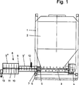
Die Mörtelmischmaschine weist ein quaderförmiges Gestell
Im Bodenbereich dieses Vorratsbehälters
Außen am Vorratsbehälter
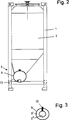
Das Mischrohr
Schließlich weist der erste Rohrabschnitt
Die Mörtelmischmaschine funktioniert wie folgt:
In dem Vorratsbehälter
In the
Der erste Rohrabschnitt
Da dieser zweite Rohrabschnitt
Insgesamt durchläuft der Mörtel in 10 bis 15 Sekunden das Mischrohr
BezugszeichenlisteLIST OF REFERENCE NUMBERS
- 11
- Gestellframe
- 22
- Vorratsbehälterreservoir
- 33
- FörderschneckeAuger
- 44
- Elektromotorelectric motor
- 55
- Dosierrohrdosing
- 66
- Dosierschneckedosing screw
- 77
- Öffnungopening
- 88th
- Mischeinrichtungmixing device
- 99
- Mischrohrmixing tube
- 9'9 '
- erster Rohrabschnittfirst pipe section
- 9''9 ''
- zweiter Rohrabschnittsecond pipe section
- 1010
- Mischwellemixing shaft
- 1111
- Mischelementmixing element
- 1212
- Wasserzuführungwater supply
- 1313
- Auslaufoutlet
Claims (2)
Priority Applications (2)
| Application Number | Priority Date | Filing Date | Title |
|---|---|---|---|
| DE19911368A DE19911368B4 (en) | 1999-03-15 | 1999-03-15 | Apparatus for producing sprayed mortar for use in wet spraying |
| EP00104397A EP1036639A3 (en) | 1999-03-15 | 2000-03-02 | Method aud device for preparing a sprayable mortar to be used in a wet spraying process |
Applications Claiming Priority (1)
| Application Number | Priority Date | Filing Date | Title |
|---|---|---|---|
| DE19911368A DE19911368B4 (en) | 1999-03-15 | 1999-03-15 | Apparatus for producing sprayed mortar for use in wet spraying |
Publications (2)
| Publication Number | Publication Date |
|---|---|
| DE19911368A1 DE19911368A1 (en) | 2000-09-21 |
| DE19911368B4 true DE19911368B4 (en) | 2012-10-04 |
Family
ID=7900956
Family Applications (1)
| Application Number | Title | Priority Date | Filing Date |
|---|---|---|---|
| DE19911368A Expired - Fee Related DE19911368B4 (en) | 1999-03-15 | 1999-03-15 | Apparatus for producing sprayed mortar for use in wet spraying |
Country Status (2)
| Country | Link |
|---|---|
| EP (1) | EP1036639A3 (en) |
| DE (1) | DE19911368B4 (en) |
Families Citing this family (2)
| Publication number | Priority date | Publication date | Assignee | Title |
|---|---|---|---|---|
| AT504803B1 (en) * | 2004-07-14 | 2008-11-15 | Johann Dipl Ing Keil | APPENDIX FOR THE PRODUCTION AND PROCESSING OF WET-SPRAYING MIXTURE |
| DE102005005394B4 (en) * | 2005-02-03 | 2008-04-30 | Alsecco Gmbh & Co Kg | Pumping and mixing device for powdered or free-flowing media and system for providing pasty media for construction purposes |
Citations (9)
| Publication number | Priority date | Publication date | Assignee | Title |
|---|---|---|---|---|
| EP0051224A2 (en) * | 1980-10-31 | 1982-05-12 | Mathis System-Technik GmbH | Process and apparatus for the continuous preparation of mortar, plaster or the like building material |
| DE8318424U1 (en) * | 1983-06-25 | 1983-11-03 | P.F.T. Putz- und Fördertechnik GmbH, 8715 Iphofen | DEVICE FOR MIXING A BUILDING MATERIAL, IN PARTICULAR MORTAR, WITH WATER |
| EP0218864A2 (en) * | 1985-09-13 | 1987-04-22 | Heidelberger Zement AG | Device and method for continuously making a hydraulically setting mass |
| DE9105027U1 (en) * | 1991-04-24 | 1991-09-19 | Winkler, Hans, 7801 Bollschweil | Mixing and feed pump |
| EP0496685A1 (en) * | 1991-01-22 | 1992-07-29 | Omniplastic S.A. | Method and device for preparing, transferring and applying continuously a fluid aqueous mineral cleaning down suspension |
| DE9319066U1 (en) * | 1993-12-14 | 1994-02-24 | Müller, Anton, 79774 Albbruck | Mortar mixer |
| DE29514183U1 (en) * | 1995-09-05 | 1995-11-02 | INOTEC GmbH Transport- und Fördersysteme, 79761 Waldshut-Tiengen | Mortar mixer |
| DE19542663A1 (en) * | 1995-11-16 | 1997-05-22 | Wagner Gmbh J | Portable continuous mixer for cement, concrete etc. |
| DE19710067C1 (en) * | 1997-03-12 | 1998-12-03 | Maxit Holding Gmbh | Device for the continuous preparation of bulk or building material mixtures |
Family Cites Families (2)
| Publication number | Priority date | Publication date | Assignee | Title |
|---|---|---|---|---|
| DE4113331A1 (en) * | 1991-04-24 | 1992-10-29 | Hans Winkler | Combined concrete mixer and pump - has screw conveyor to drive ingredients through mixing chambers |
| DE29906703U1 (en) * | 1999-04-15 | 1999-08-12 | Unibautech Grossenhainer Maschinenfabrik GmbH, 01558 Großenhain | Mixers for the production of suspensions |
-
1999
- 1999-03-15 DE DE19911368A patent/DE19911368B4/en not_active Expired - Fee Related
-
2000
- 2000-03-02 EP EP00104397A patent/EP1036639A3/en not_active Withdrawn
Patent Citations (9)
| Publication number | Priority date | Publication date | Assignee | Title |
|---|---|---|---|---|
| EP0051224A2 (en) * | 1980-10-31 | 1982-05-12 | Mathis System-Technik GmbH | Process and apparatus for the continuous preparation of mortar, plaster or the like building material |
| DE8318424U1 (en) * | 1983-06-25 | 1983-11-03 | P.F.T. Putz- und Fördertechnik GmbH, 8715 Iphofen | DEVICE FOR MIXING A BUILDING MATERIAL, IN PARTICULAR MORTAR, WITH WATER |
| EP0218864A2 (en) * | 1985-09-13 | 1987-04-22 | Heidelberger Zement AG | Device and method for continuously making a hydraulically setting mass |
| EP0496685A1 (en) * | 1991-01-22 | 1992-07-29 | Omniplastic S.A. | Method and device for preparing, transferring and applying continuously a fluid aqueous mineral cleaning down suspension |
| DE9105027U1 (en) * | 1991-04-24 | 1991-09-19 | Winkler, Hans, 7801 Bollschweil | Mixing and feed pump |
| DE9319066U1 (en) * | 1993-12-14 | 1994-02-24 | Müller, Anton, 79774 Albbruck | Mortar mixer |
| DE29514183U1 (en) * | 1995-09-05 | 1995-11-02 | INOTEC GmbH Transport- und Fördersysteme, 79761 Waldshut-Tiengen | Mortar mixer |
| DE19542663A1 (en) * | 1995-11-16 | 1997-05-22 | Wagner Gmbh J | Portable continuous mixer for cement, concrete etc. |
| DE19710067C1 (en) * | 1997-03-12 | 1998-12-03 | Maxit Holding Gmbh | Device for the continuous preparation of bulk or building material mixtures |
Also Published As
| Publication number | Publication date |
|---|---|
| DE19911368A1 (en) | 2000-09-21 |
| EP1036639A2 (en) | 2000-09-20 |
| EP1036639A3 (en) | 2002-07-10 |
Similar Documents
| Publication | Publication Date | Title |
|---|---|---|
| EP1914056B1 (en) | Device for the continuous and intensive mixing of dry mortar | |
| DE3532722C2 (en) | ||
| DE2637558A1 (en) | METHOD AND DEVICE FOR GENERATING A CONTINUOUS FLOW OF MATERIAL | |
| DE202007015262U1 (en) | Mixing and conveying device for mortar | |
| DE3809661A1 (en) | Apparatus for continuously mixing a building material | |
| DE2729863A1 (en) | METHOD AND DEVICE FOR PIPE CONVEYING OF MATERIALS | |
| DE3704461C2 (en) | ||
| EP0111014A1 (en) | Method and device for separating and recycling all constituents of waste concrete | |
| DE19511585B4 (en) | Method and device for concrete preparation in a drum mixing system | |
| EP0255633B1 (en) | Method and device for making binding material or for mixing sludge | |
| DE19911368B4 (en) | Apparatus for producing sprayed mortar for use in wet spraying | |
| DE3206742A1 (en) | METHOD AND DEVICE FOR APPLYING MORTAR OR CONCRETE | |
| DE3733409A1 (en) | Device for mixing components of a mixture and use thereof for producing bentonite suspensions and sheet-pile screen suspensions | |
| DE2165148A1 (en) | Method and apparatus for mixing dry and liquid materials and for making reinforced plastic articles | |
| EP2239120A2 (en) | Transport vehicle for delivering a binder/aggregate mixture | |
| EP0864408B1 (en) | Device for continuously tempering mixtures of bulk material or building material | |
| EP1676630B1 (en) | Mixing apparatus | |
| EP0574728B1 (en) | Checking and transporting of a building material mixture | |
| DE19917056A1 (en) | Suspension mixer has interacting paddles and baffles to create homogenous, stable and lump-free product | |
| DE10316232B4 (en) | Method and device for feeding an extruder | |
| EP0561291A1 (en) | Device for making plastering mortar ready to be used | |
| DE102006043596B3 (en) | Conveying device for a material mixture from components, comprises mixing container having a mixing device for the materials, discharge device for discharging the materials from the mixing container, and flow mixer for different components | |
| DE3031201A1 (en) | Extruder force feed for film plus granulate - granulate laterally enters conical part of vertical screw for film | |
| DE2523374A1 (en) | Continuous mortar mixer with endless screw metering dry mix - has partly filled mixing chamber with water inlet and screw discharge | |
| DE2953699A1 (en) |
Legal Events
| Date | Code | Title | Description |
|---|---|---|---|
| OM8 | Search report available as to paragraph 43 lit. 1 sentence 1 patent law | ||
| 8110 | Request for examination paragraph 44 | ||
| R082 | Change of representative |
Representative=s name: MAIWALD PATENTANWALTS GMBH, DE Representative=s name: MAIWALD PATENTANWALTS GMBH, 40213 DUESSELDORF, DE |
|
| R018 | Grant decision by examination section/examining division | ||
| R020 | Patent grant now final |
Effective date: 20130105 |
|
| R119 | Application deemed withdrawn, or ip right lapsed, due to non-payment of renewal fee |
Effective date: 20131001 |